You might consider a ex-Soviet pancake. The best tube I have used so far. They are available on eBay - look for any SBT or SI types. They run at around 400 V and cost from around USD 50.
My most recent (about 3 years old) circuit doesn't use any transformer. It is based on a MC34063 as boost converter followed by a voltage multiplier, here are some photos. As usual it was a quick fix, I guess I need to do some reverse engineering on my own circuit...

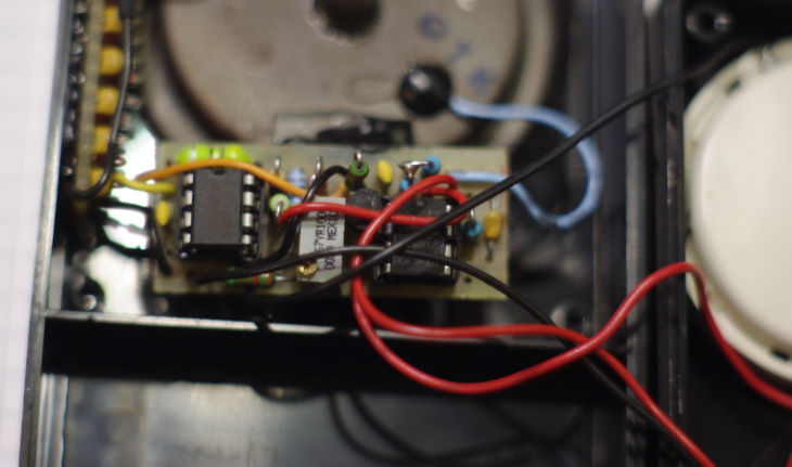
The 8-pin bug to the left is the MC34063, the one to the right is a 7555 as pulse-shaper (same as in the above circuit).
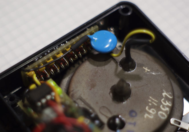
This is the voltage multiplier - using just plain 1N4148 and 50V ceramic capacitors for the stages. Only the last capacitor is a kV-type (of course mounted the wrong side down for me to read it now...)
Oh, yeah, the thing at the bottom is a Soviet SI8B alpha/beta/gamma tube.
P.S.: Hah, the forum is not unicode

the cyrillic letters came out as smileys and question marks

Ok, in "code" it works. So here are the transcriptions:
SBT    ???
SI     ??
SI8B   ??8?
oh man, this is crazy. It worked in preview, but when submitted the cyrillics is gone again. And this in the year 2014 - I thought we were past character coding issues...


