Author Topic: Another Power Supply  (Read 30576 times)

0 Members and 1 Guest are viewing this topic.

Offline braddrew0Topic starter

  • Regular Contributor
  • *
  • Posts: 79
  • Country: au
Another Power Supply
« on: January 28, 2016, 09:18:21 am »
Hi Guys,


Using Dave's uSupply as inspiration, I've designed a 20V, 2A variable power supply. This is my biggest project to date, and I'd appreciate any feedback at all you can offer. Even if the design is completely messed up, I've had a lot of fun and learnt a lot so far :)

The design is broken into a bunch of blocks. I'll go over each one in turn with justification over why I picked certain components over others (which a lot of the time was because I had them on hand...)

The design will be fed from mains via a transformer with an 18VAC output. This passes through the fuse, bridge recitifier and is filtered, giving around 26V output. The ripple is load dependent but I calculated max of around 1V. I used four 10,000uF caps vice one single big one for two reasons. Firstly, it was cheaper, and secondly I thought it might give me a bit of redundancy if one fails.

There are two secondary chip regulated supplies, being 5V and 3.3V. The 5V is fed from 26V as I wanted all the low power devices to power up before the main supply (more on that later). The 3.3V is used to drive the uC and peripherals.

Along with the 3.3V supply, I've made a simple linear 4.096V supply. The ADR4540 is a 4.096V reference that I have excess of here. C8 and C15 provide supply buffering. D1/Q1/R2/R3 is a simple 100mA constant current source. This is fed into the gate of the MOSFET. The AD818 compares the output voltage to the reference, and D2 allows it to sink current only. So the basic idea is the constant current supply is fed into the MOSFET, then sunk when not required. I think this is more complicated than it needs to be (my original design ran the ADR4540 into a unity gain amp) but I'm also interested to test out the principle of this circuit (it's based on something similar by Walter Jung).

Most of the uC circuitry is standard. It will be run on 3.3V, including the i2c line. P2 is a NewHaven display which is controlled via i2c. There are two rotary encoders (current and voltage) and two switches (reset and enable). The capacitor bank on the RHS is for filtering the 4.096V IC's (ADC, DACs, OpAmps).

U8 and U9 are two i2c DACs. I've got excess of these at home, hence the choice. One is to set the reference voltage for current (0 - 4V => 0 - 2A) and the other for the output voltage (0 - 4V => 0 - 20V). The ADC is to return the signals back to the uC so I can display set and actual voltage/current. It's a 4 channel i2c because that's what I had lying around.

The bulk of the power supply is in the top right. It's a three stage topology, with a pre-regulator, current control and MOSFET voltage control. I wanted to use a pre-regulator for two reasons, firstly to remove the ripple from the 26V line and secondly so I could use the enable port to switch the supply on/off. This means the unit will always start/restart with enable low, hopefully stopping initial voltage spikes. The output of the pre-regulator should be around 23.5V.

The current control is achieved with a simple 0.01ohm shunt and a differential amplifier. It has a high gain on it (50) to convert the shunt current into the 0 - 4V range. Like Dave's design, this sinks the MOSFET gate when the current is higher than the set value.

Voltage control is again reasonably standard, with a resistor divider converting 0-20V into 0-4V. This is also tapped off to be read by the ADC.


That's all I can think of at the moment - I'm holding off on the board layout until I'm convinced that the design is workable in it's current state. I'd love to hear any feedback or criticism that any of you have. Like I said this is my biggest project to date, and I don't know what I don't know... so help me learn :)


Regards,


Brad


Offline braddrew0Topic starter

  • Regular Contributor
  • *
  • Posts: 79
  • Country: au
Re: Another Power Supply
« Reply #1 on: January 29, 2016, 04:50:42 am »
Bump.... any feedback?
 

Offline dadler

  • Supporter
  • ****
  • Posts: 851
  • Country: us
Re: Another Power Supply
« Reply #2 on: January 29, 2016, 05:21:57 am »
The ADA4177 is not a single supply op amp. The current shunt diff amp seems to be relying on voltage near ground, but it can only read Vss+1.5V.
 

Offline viperidae

  • Frequent Contributor
  • **
  • Posts: 306
  • Country: nz
Re: Another Power Supply
« Reply #3 on: January 29, 2016, 05:25:16 am »
A 5v linear regulator powered from a 26v source is going to have to drop 21v. That's going to be 2.1w for every 100ma.
 

Online Kleinstein

  • Super Contributor
  • ***
  • Posts: 14197
  • Country: de
Re: Another Power Supply
« Reply #4 on: January 29, 2016, 11:44:19 am »
The voltage regulating OP likely needs something to slow it down to prevent oscillations.

The current regulation part does not look good to. 

The Sourcefollower output stage is tricky: ouput is limited to something like 2 or 3 volt below the driving voltage. With the OP supply at only 4 V this is not much.  Also there is a danger of having two much of a gate voltage if the output is still high and the driver goes low very fast.
 

Offline braddrew0Topic starter

  • Regular Contributor
  • *
  • Posts: 79
  • Country: au
Re: Another Power Supply
« Reply #5 on: January 30, 2016, 01:57:23 am »
Thanks guys,

dadler - Good pickup, thanks! I've replaced with ADA4084.

viperidae - One of my aims for this was to work on cooling with SMD components. The D2PAK can handle 3W power dissipation with a 30mm x 30mm plane under ground. I think I will be right on the limit of this - my plan was to place the regulator on the bottom of the board with a solid ground plane, and no vias within 30mm of the device. Do you think this is suitable? If not, in terms of alternatives, would the best option be a pre-regulator (say a 7812) which will spread the power dissipation over two devices? Thanks!

Kleinstein - Thanks, this is great! On oscillations, is there a good rule of thumb on how much capacitance to add? I tried to read up on analysing the control system to look at stability, but most references go straight into adding poles/zeros to the transfer function. I did control theory in university about 15 years ago (aeronautical engineering) but I remember having nightmares over this stuff and I think it will take a good couple of months to get my head back around it.
On the source follower - with a rail to rail amp like ADA4084, will this still be an issue?
On the gate voltage - I'm not 100% sure what you mean here. Wouldn't the gate voltage in the absolute worst case be limited to the OP supply?


Thanks guys - I really appreciate the help  :-+
 

Offline motocoder

  • Supporter
  • ****
  • Posts: 769
  • Country: us
  • Electrical Engineer
Re: Another Power Supply
« Reply #6 on: January 30, 2016, 04:24:38 am »
Hi braddrew0 -

One comment I had is about using the MOSFET as the main series/pass regulator. I have always been told that the typical power MOSFET is suitable for switching applications, but may not be a good choice for a linear regulator. The reason for this is that in the typical switching application, the MOSFET is either off and not conducting, and hence not drawing any power, or in saturation with low on resistance, and thus not dropping much power. The primary power dissipation is due to the period where it switches from off to on or vice-versa. The MOSFETs are optimized to minimize switching time, and not to operate in linear mode. If you try and operate them in linear mode, for example in your circuit, you may end up dropping significant voltage across the MOSFET, and hence dissipating significant power. There is an effect called the "Spirito Effect" that can in these situations lead to a failure of the MOSFET. You can read more about it in this app note, or just search for "Spirito Effect"

https://www.fairchildsemi.com/application-notes/AN/AN-4161.pdf

So I'm not saying it's bad to use a MOSFET, but read that article and make sure you are operating the MOSFET in the Safe Operating Area (which might be more restrictive than you think due to the Spirito effect).

For that reason, you will often see series voltage regulator designs using some sort of BJT device rather than the MOSFET, or perhaps an IGBT for very high voltage designs.

I'm certainly not an expert in this area - so please confirm what I'm saying independently.

And kudos on expanding your knowledge with this project; I think it's a great idea.


Offline dadler

  • Supporter
  • ****
  • Posts: 851
  • Country: us
Re: Another Power Supply
« Reply #7 on: January 30, 2016, 07:06:57 am »
The SOA graph may or may not show a mosfet as being DC rated.

There are mosfets designed for linear operation, such as the IXYS Linear2 series:

http://www.mouser.com/ProductDetail/IXYS/IXTQ60N20L2/?qs=%2fha2pyFaduh78JBcne8bXIOtGyZxvW3LDkwxtjcUKhF9DBxmlqF3%252bg%3d%3d
 

Offline mij59

  • Frequent Contributor
  • **
  • Posts: 693
  • Country: nl
Re: Another Power Supply
« Reply #8 on: January 30, 2016, 07:41:10 am »
U10 is powered by 4.096V you won't get much output voltage, connect it to +26V.
The common mode voltage of U10 and U7 need to include zero Volt.
Using 40.000 uF as filter caps is a bit over the top, what's wrong with 4700 uF ?
The current sense amp has an attenuation of 50, you need to swap the resistors 10k / 500k, check if U6 can handle the high common mode voltage.
 

Offline braddrew0Topic starter

  • Regular Contributor
  • *
  • Posts: 79
  • Country: au
Re: Another Power Supply
« Reply #9 on: January 30, 2016, 09:38:50 am »
motocoder - That's something I didn't even think of... I must have read through the app note a dozen times without seeing a big graph saying "safe operating area"...  |O I've switched over to MJB44H11T4-A from STM (http://www.digikey.com.au/product-detail/en/MJB44H11T4-A/497-15455-1-ND/5244680). The 20V/2A is right on the limits of safe DC operation. One other question I do have though is the parameter "VEBO - Emitter-Base Voltage" of 5V. Does this mean that if I want to pass 20V from the emitter I need 15V on the base? Thanks!

dadler - Thanks again - I've switched over to a BJT but I've bookmarked these. I've got another project in mind that uses PWM which looks perfect for these.

mij59 - I've replaced U10 and U7 with the same ADA4084. Both are fed from the 26V supply now. My initial concern on using the 26V is that it wouldn't be a "stable" 26V... so wouldn't that just add ripple to the output? If I need 15V to drive 20V though, it's obviously not going to work with 4.096V, so thanks!
On the caps - the MIC29302 had a maximum input voltage of 26V, and I've configured it for about 23.5V output. I initially had 4700uF but at maximum draw (I gave it around 2.5A to be safe) the ripple was too high and would drop below 23.5V. With 40,000uF, I calculated around 1V maximum ripple, which gives me around 1.5V for the dropout in the regulator. Is this the correct process?
On common mode voltage - I'm finding it difficult to interpret this from the datasheet (http://www.analog.com/media/en/technical-documentation/data-sheets/ADA4084-1_4084-2_4084-4.pdf). I'm assuming +26V would give similar data to +/- 15V except without the ability to exactly hit the 0V rail. The graph on page 24 - the way I interpret that, over most ambient temperature conditions, the behavior of the differential amp will be non-linear inside about 100uV - am I reading that correctly? Thanks for your help!

Revision A2 schematic attached - thanks again all!

Brad
 

Offline mij59

  • Frequent Contributor
  • **
  • Posts: 693
  • Country: nl
Re: Another Power Supply
« Reply #10 on: January 30, 2016, 10:44:47 am »

mij59 - I've replaced U10 and U7 with the same ADA4084. Both are fed from the 26V supply now. My initial concern on using the 26V is that it wouldn't be a "stable" 26V... so wouldn't that just add ripple to the output? If I need 15V to drive 20V though, it's obviously not going to work with 4.096V, so thanks!
On the caps - the MIC29302 had a maximum input voltage of 26V, and I've configured it for about 23.5V output. I initially had 4700uF but at maximum draw (I gave it around 2.5A to be safe) the ripple was too high and would drop below 23.5V. With 40,000uF, I calculated around 1V maximum ripple, which gives me around 1.5V for the dropout in the regulator. Is this the correct process?
On common mode voltage - I'm finding it difficult to interpret this from the datasheet (http://www.analog.com/media/en/technical-documentation/data-sheets/ADA4084-1_4084-2_4084-4.pdf). I'm assuming +26V would give similar data to +/- 15V except without the ability to exactly hit the 0V rail. The graph on page 24 - the way I interpret that, over most ambient temperature conditions, the behavior of the differential amp will be non-linear inside about 100uV - am I reading that correctly? Thanks for your help!
Revision A2 schematic attached - thanks again all!

Brad
With 18V AC input is not much room for regulation, if you want an output voltage of 20V get a higher input voltage, ( rule of thumb AV voltage in is DC voltage out )
The pre-regulator is not necessary, its only decreases the room for regulation.

The data sheet of the AD4084 states that input and output are rail to rail, so it shouldn’t be a problem.
The input stage of most opamp's won't work properly when the input voltage comes within a few volts of the one of the power rails, e.g. a LM324 with a single power supply will work with input voltage form zero  to V+ minus 1.5V.


Offline motocoder

  • Supporter
  • ****
  • Posts: 769
  • Country: us
  • Electrical Engineer
Re: Another Power Supply
« Reply #11 on: January 30, 2016, 01:43:14 pm »
motocoder - That's something I didn't even think of... I must have read through the app note a dozen times without seeing a big graph saying "safe operating area"...  |O I've switched over to MJB44H11T4-A from STM (http://www.digikey.com.au/product-detail/en/MJB44H11T4-A/497-15455-1-ND/5244680). The 20V/2A is right on the limits of safe DC operation. One other question I do have though is the parameter "VEBO - Emitter-Base Voltage" of 5V. Does this mean that if I want to pass 20V from the emitter I need 15V on the base?

The VEBO Rating of a BJT is the maximum allowable voltage that the emitter-base junction of a transistor can handle before it becomes damaged or destroyed.

Also, see dadler's comment; if you want,  it's OK to stick with a MOSFET, just make sure you use one rated for linear operation, and check the SOA graph in the datasheet to make sure you're OK there.

Also, when checking specs, you want to check the amperage through the transistor and the voltage drop across it - not the output voltage. For example, if the rectified unregulated voltage is 30V at full current, and someone shorts the output or programs the output voltage to be near zero volts, then the voltage drop across the transistor might be as high as 30V. If you are having trouble finding a device that can support this, then you can parallel two or more devices, but be sure to add a small value emitter or source resistor to each to ensure the current across the devices is distributed fairly evenly. I think that you should be able to find a single transistor that can easily to support this though, but you will need to heatsink it.

You can also also add a current limiting feature if you want. There are ICs like the LM723 that you could use, instead of the op-amp, which can still drive the external transistor but which have a current limit feature built in. You just need to add a current sense resistor and connect things appropriately to enable that - see the data sheet. You can also add a current limit feature to your existing, op-amp based, circuit - let me know if you want an example of that. BTW, the LM723 is what is used in those Astron linear supplies that are popular with HAM radio folks. It's kind of an old IC, but it's cheap and works.

« Last Edit: January 30, 2016, 01:51:44 pm by motocoder »
 

Offline braddrew0Topic starter

  • Regular Contributor
  • *
  • Posts: 79
  • Country: au
Re: Another Power Supply
« Reply #12 on: January 31, 2016, 04:43:38 am »

With 18V AC input is not much room for regulation, if you want an output voltage of 20V get a higher input voltage, ( rule of thumb AV voltage in is DC voltage out )
The pre-regulator is not necessary, its only decreases the room for regulation.

The data sheet of the AD4084 states that input and output are rail to rail, so it shouldn’t be a problem.
The input stage of most opamp's won't work properly when the input voltage comes within a few volts of the one of the power rails, e.g. a LM324 with a single power supply will work with input voltage form zero  to V+ minus 1.5V.


I only had two considerations for the pre-regulator - reducing ripple and giving me an "enable" switch. I guess for the type of supply I'm trying to build, the levels of ripple I'll get from the op amp shouldn't be prohibitive. I like your rule of thumb - that's handy to know :) Do you think there are any issues if I replace the pre-reg with a similar BJT to the main pass transistor and use that as an enable/disable? I was trying to avoid using a relay if I could but I'd love to have the ability to isolate... Thanks again!


The VEBO Rating of a BJT is the maximum allowable voltage that the emitter-base junction of a transistor can handle before it becomes damaged or destroyed.

Also, see dadler's comment; if you want,  it's OK to stick with a MOSFET, just make sure you use one rated for linear operation, and check the SOA graph in the datasheet to make sure you're OK there.

Also, when checking specs, you want to check the amperage through the transistor and the voltage drop across it - not the output voltage. For example, if the rectified unregulated voltage is 30V at full current, and someone shorts the output or programs the output voltage to be near zero volts, then the voltage drop across the transistor might be as high as 30V. If you are having trouble finding a device that can support this, then you can parallel two or more devices, but be sure to add a small value emitter or source resistor to each to ensure the current across the devices is distributed fairly evenly. I think that you should be able to find a single transistor that can easily to support this though, but you will need to heatsink it.

You can also also add a current limiting feature if you want. There are ICs like the LM723 that you could use, instead of the op-amp, which can still drive the external transistor but which have a current limit feature built in. You just need to add a current sense resistor and connect things appropriately to enable that - see the data sheet. You can also add a current limit feature to your existing, op-amp based, circuit - let me know if you want an example of that. BTW, the LM723 is what is used in those Astron linear supplies that are popular with HAM radio folks. It's kind of an old IC, but it's cheap and works.

I think I'm thinking about VEBO wrong... so it's basically saying the base should never be more than 5V higher than the emitter? I'm just trying to work out if I'm going to damage something here...

On the MOSFET, to be honest most linear regulators I've seen use a BJT (and I think I remember Dave mentioning it in the uSupply videos?) and really the only reason I went that way was because "Oh cool, MOSFET!" rather than any real requirement... I'm happy to stick with BJT for anything that doesn't need switching, and if I ever find myself in a situation where that doesn't work, I'll know where to look :)

I meet the maximum continuous current and maximum DC power ratings, but the only other voltage information in the sheet (http://www.onsemi.com/pub_link/Collateral/MJB44H11-D.PDF) I can see is saturation voltage - is that the same thing?

With respect to current limiting, this has probably been the aspect of this project which is most dis-similar from any I've done before. Every one seems to current limit a different way - I wanted to try and get a "minimalistic" design that works reasonably well, hence I didn't buffer any of the outputs or anything like that. I've tried to stay away from using the all in one IC's because I'm trying to learn how these things work - from what I've read, there is a lot of "tuning" that needs to be done of your control circuit, and thats the bit I'm trying to figure out (which parts matter, and what specs on those parts matter) if that makes sense? More than happy to see any other designs that you can recommend if you're happy to share. Thanks again!

Brad
 

Offline motocoder

  • Supporter
  • ****
  • Posts: 769
  • Country: us
  • Electrical Engineer
Re: Another Power Supply
« Reply #13 on: January 31, 2016, 05:33:49 am »
I think I'm thinking about VEBO wrong... so it's basically saying the base should never be more than 5V higher than the emitter? I'm just trying to work out if I'm going to damage something here...

The notation means voltage (V) from emitter (E) to base (B) with collector open (O). So this is in effect the reverse breakdown voltage of the base emitter junction. I don't think that should be an issue for you unless you've got something outside the supply feeding voltage back in.

On the MOSFET, to be honest most linear regulators I've seen use a BJT (and I think I remember Dave mentioning it in the uSupply videos?) and really the only reason I went that way was because "Oh cool, MOSFET!" rather than any real requirement... I'm happy to stick with BJT for anything that doesn't need switching, and if I ever find myself in a situation where that doesn't work, I'll know where to look :)

Sounds like a good idea. You'll certainly have an easier time finding a suitable device that way.

I meet the maximum continuous current and maximum DC power ratings, but the only other voltage information in the sheet (http://www.onsemi.com/pub_link/Collateral/MJB44H11-D.PDF) I can see is saturation voltage - is that the same thing?

The saturation voltage is the voltage across the collector-emitter junction when the transistor is completely turned on. Lower is better as it means your wasting less power in the transistor.

With respect to current limiting, this has probably been the aspect of this project which is most dis-similar from any I've done before. Every one seems to current limit a different way - I wanted to try and get a "minimalistic" design that works reasonably well, hence I didn't buffer any of the outputs or anything like that. I've tried to stay away from using the all in one IC's because I'm trying to learn how these things work - from what I've read, there is a lot of "tuning" that needs to be done of your control circuit, and thats the bit I'm trying to figure out (which parts matter, and what specs on those parts matter) if that makes sense? More than happy to see any other designs that you can recommend if you're happy to share. Thanks again!

Makes total sense. Have some fun with the circuit, and once you have it working you can always go back and make a rev 2. I'd do the same thing. Please check back in and let us all know how it goes.

BTW - I think a really great way to learn about this topic is to download the manual for some of the older linear power supplies, and read the "Theory of Operation" section. I am particularly fond of the old HP 6114a/6115a supplies, which have a really good section like that in their manual. The schematic is also worth looking through.

« Last Edit: January 31, 2016, 05:35:36 am by motocoder »
 

Offline braddrew0Topic starter

  • Regular Contributor
  • *
  • Posts: 79
  • Country: au
Re: Another Power Supply
« Reply #14 on: January 31, 2016, 05:46:56 am »
Great suggestion - I'll definitely post here when built. Thanks for all your help!  :-+
 

Offline mij59

  • Frequent Contributor
  • **
  • Posts: 693
  • Country: nl
Re: Another Power Supply
« Reply #15 on: January 31, 2016, 07:03:30 am »

I only had two considerations for the pre-regulator - reducing ripple and giving me an "enable" switch. I guess for the type of supply I'm trying to build, the levels of ripple I'll get from the op amp shouldn't be prohibitive. I like your rule of thumb - that's handy to know :) Do you think there are any issues if I replace the pre-reg with a similar BJT to the main pass transistor and use that as an enable/disable? I was trying to avoid using a relay if I could but I'd love to have the ability to isolate... Thanks again!

You could use the dac which controls the output voltage  as an enable switch, no need for an extra switching element in the main power path.
Or use then circuit in the attached file PS2803_V3_main.pdf using the  mosfet T4, for the control circuit see PS2803_V3.pdf.

When using BJT's keep in mind that the output of an opamp has a  limited current source and sink capability. 


Online Kleinstein

  • Super Contributor
  • ***
  • Posts: 14197
  • Country: de
Re: Another Power Supply
« Reply #16 on: January 31, 2016, 08:54:57 am »
Using a MOSFET instead of a BJT as the power device gives extra choices in where to put the current sensing resistor, because there is essentially not control current, so source and drain side current are essentially the same. The main advantages with BJTs is that it's easier to have pwoer divices in parallel, usually lower cost, lower control voltage and less current dependent properties.

The choice of where to have the current sensing rsistor is a main decission in the design.  The other important point is whether the ouput stage is controlling the current (like a BJT in emitter circuit) or the voltage (like an emitter follower).
The Basic regulator circuit uses an emitter follower and a current sensing resistor on the low side. This works good with BJTs  up to about 30 V - the voltage swing a normal OP can provide.

The second major type uses a floating second supply for the regulator circuit itself. The shunt is at the emitter/source of the power device, thus usally the positive output. This version is very flexible (choice of BJT or MOSFET and easy to adapt for low and high voltages) but needs a second isolated supply / transformer winding.
 

Offline motocoder

  • Supporter
  • ****
  • Posts: 769
  • Country: us
  • Electrical Engineer
Re: Another Power Supply
« Reply #17 on: January 31, 2016, 02:16:02 pm »
The second major type uses a floating second supply for the regulator circuit itself. The shunt is at the emitter/source of the power device, thus usally the positive output. This version is very flexible (choice of BJT or MOSFET and easy to adapt for low and high voltages) but needs a second isolated supply / transformer winding.

You can use a shunt regulator instead of a second transformer winding, can be as simple as a zener diode, to provide the floating supply for that. I played around with this circuit on the current source I am working on currently, and it works quite well.

Also, Linear and TI make high side current sense amplifiers, for example the LTC6101 or LTC6101HV. I think these are effectively just the same circuit (with the shunt regulator and a MOSFET to reflect the current from high side to low side) all in one package.
 

Offline braddrew0Topic starter

  • Regular Contributor
  • *
  • Posts: 79
  • Country: au
Re: Another Power Supply
« Reply #18 on: February 01, 2016, 07:05:31 am »
You could use the dac which controls the output voltage  as an enable switch, no need for an extra switching element in the main power path.
Or use then circuit in the attached file PS2803_V3_main.pdf using the  mosfet T4, for the control circuit see PS2803_V3.pdf.

When using BJT's keep in mind that the output of an opamp has a  limited current source and sink capability.

The only thing that stopped me from going down that route is that I was worried if I just set the DAC to zero that there would still be current flow through the amp (DC bias), which would cause a small amount of current flow through main line.... your solution is much more elegant though!

Is this your design? I've got to say, I really wish I'd seen this before I started because it answers a lot of my questions! It took about an hour of staring at it last night before I could make sense of what every functional block did, but I think I have a reasonable understanding now, although the pre-regulator (specifically the use of the NAND gates and the 100Hz signal) will take a bit more work. In general, it looks like the ideas you used are similar to where I'm trying to go, but the execution is light years ahead.

The two big take away points for me I think are that you seem to use a lot of protection circuits (isolation, clamping diodes, the ADuMs) which are absent in mine, and your 'switches' (BJT and MOSFET) have much more complex driver circuitry - mine is more a case of "put current in and hope it works", whereas yours have levels upon levels (which I assume keeps them well within their safe operating area). This is an area I definitely need to work on!

Using T4 to sink the output of the voltage comparator op amp is exactly what I was after for mine design - that removes any bias and gives me a specific enable/disable line from the uC. I'll add it to my next revision!

I also love the 15V supply you've made from R1/D3. I'm going to have a play around with this idea and see if I can limit the voltage entering my 5V regulator. This will save me from having to use a second regulator.

I'll probably have a bunch more questions on this design as I absorb it a bit better (if you're happy to answer) but I'll start with one - I can't get my head around the direction of polarisation of C1... the way I figure, you should have a 'high' voltage (you've got 50V, I'm guessing maybe this is a rectified ~48VAC input that you later constrain in the 0-50V bracket?) from BR1 passing through the junction between the two bridges to the negative terminal of C1, and D1/D4 should constrain the output of BR2 to 15V onto the pre-regulator FET T1. This would mean the voltage is higher on negative terminal of the cap than the positive, which is back to front right?

Thanks once again - this design is great inspiration for me! :)

Using a MOSFET instead of a BJT as the power device gives extra choices in where to put the current sensing resistor, because there is essentially not control current, so source and drain side current are essentially the same. The main advantages with BJTs is that it's easier to have pwoer divices in parallel, usually lower cost, lower control voltage and less current dependent properties.

The choice of where to have the current sensing rsistor is a main decission in the design.  The other important point is whether the ouput stage is controlling the current (like a BJT in emitter circuit) or the voltage (like an emitter follower).
The Basic regulator circuit uses an emitter follower and a current sensing resistor on the low side. This works good with BJTs  up to about 30 V - the voltage swing a normal OP can provide.

The second major type uses a floating second supply for the regulator circuit itself. The shunt is at the emitter/source of the power device, thus usally the positive output. This version is very flexible (choice of BJT or MOSFET and easy to adapt for low and high voltages) but needs a second isolated supply / transformer winding.

You can use a shunt regulator instead of a second transformer winding, can be as simple as a zener diode, to provide the floating supply for that. I played around with this circuit on the current source I am working on currently, and it works quite well.

Also, Linear and TI make high side current sense amplifiers, for example the LTC6101 or LTC6101HV. I think these are effectively just the same circuit (with the shunt regulator and a MOSFET to reflect the current from high side to low side) all in one package.

I like the idea of using the BJT for this design (for cheap, simple, low power), and I can see I'll probably want to have a go a second design when I want something slightly more complex. On the current sense resistor - this is probably another misunderstanding I have on how transistors work, but why is having the sense resistor on the high side more complex?

Thanks! :)
 

Offline mij59

  • Frequent Contributor
  • **
  • Posts: 693
  • Country: nl
Re: Another Power Supply
« Reply #19 on: February 01, 2016, 08:13:14 am »


I'll probably have a bunch more questions on this design as I absorb it a bit better (if you're happy to answer) but I'll start with one - I can't get my head around the direction of polarisation of C1... the way I figure, you should have a 'high' voltage (you've got 50V, I'm guessing maybe this is a rectified ~48VAC input that you later constrain in the 0-50V bracket?) from BR1 passing through the junction between the two bridges to the negative terminal of C1, and D1/D4 should constrain the output of BR2 to 15V onto the pre-regulator FET T1. This would mean the voltage is higher on negative terminal of the cap than the positive, which is back to front right?


The schematic I posted is version 3,  don't use the pre-regulator,  now several dead mosfet's later I have arrived at version 6.
Controlling the output voltage of the pre-regulator turned out to be the most challenging.

The main power path is through Br1, T1 and  L1.
C5, C6 and Br2 are used as a voltage multiplier / level shifter, the voltage on + Br2 will be 15V higher than on +Br1.
The opto coupler U2 is used to switch T1 on, when T1 is on, the voltage on the gate of T1 will be about 15V higher than on the source.
 

Online Kleinstein

  • Super Contributor
  • ***
  • Posts: 14197
  • Country: de
Re: Another Power Supply
« Reply #20 on: February 01, 2016, 05:07:28 pm »
Having the current sensing resistor high side is more complicated if one needs to transfer the current signal to the low side to combine it with the voltage sensing. There are high side current sensor chip, but many of them are rather slow which causes trouble in the regulation loop. The second problem is that they usually need a minimum voltage to ground - so they may not work at low output voltages (e.g. < 2 V).  Having the shunt high side, directly at the supply is a little easier ( no low voltage there, and less voltage swing), but the controlling current is not measured in that case - so it will not be precise with BJTs.

The floating voltage regulator usually needs a real second winding. One could get away with current sources, but this is tricky as higher voltage and negative supply is than helpful or needed. A possible alternative would be a small DCDC converter or royer converter if the regulator and display don't need much current.
It is possible to use a shunt regulation for a floating current regulation on a high side shunt, especially with analog setting via pot. With a digital setting one needs a transfer of the setpoint, that needs quite some effort.

P.s.:
The schematic PS2803 shows the problems with high side current sensing and rather poor solution to that. divides down the shunt voltage to bring it to convenient levels and than need high end OPs to bring it back to workable levels. So high effort (precision, e.g. < 0.1 % resistors and higher end effort) and still poor performance.
With such a low power version one can get away without preregulator.
« Last Edit: February 01, 2016, 05:18:51 pm by Kleinstein »
 

Offline mij59

  • Frequent Contributor
  • **
  • Posts: 693
  • Country: nl
Re: Another Power Supply
« Reply #21 on: February 01, 2016, 06:04:57 pm »
The schematic PS2803 shows the problems with high side current sensing and rather poor solution to that. divides down the shunt voltage to bring it to convenient levels and than need high end OPs to bring it back to workable levels. So high effort (precision, e.g. < 0.1 % resistors and higher end effort) and still poor performance.
With such a low power version one can get away without preregulator.

The current sensing is reference to 0B, and is floating with respect to the voltage sensing reference 0A.
 

Online Kleinstein

  • Super Contributor
  • ***
  • Posts: 14197
  • Country: de
Re: Another Power Supply
« Reply #22 on: February 01, 2016, 07:12:13 pm »
The current sensing is reference to 0B, and is floating with respect to the voltage sensing reference 0A.

Sorry, I have not seen the the voltage regulator is floating. It was not that obvious as the floating supply is somewhere hidden. So no high precision resistors needed and performance can be good. But still there is a lot of effort with a floating supply and isolation for current setting DAC.  If you already have a floating supply one could have chosen the classic fully floating regulator: this would have saved the isolation and the special high voltage OP. I still think the circuit might have problems with low output voltages, as the current sink is not working all the way down to 0.
 

Offline SteveP

  • Contributor
  • Posts: 24
  • Country: us
Re: Another Power Supply
« Reply #23 on: February 02, 2016, 03:12:07 am »
Hi,

I think you're just a bit behind where I am with my power supply design, so I offer the following general comments based on my experience to date:

1) I am guessing that you're not (yet) running any simulations. I *strongly* suggest you start doing so. You'll find more problems than you'd ever think existed once you do. Much easier to fix in simulation than on a breadboard and, believe me, there are lots of ways to get a power supply to misbehave. I'm using LTSpice and while it has a lot of frustrating aspects to it, it is free, easy to install, and is saving me a boatload of time and parts.

2) You don't mention any targets for performance--like how you expect the supply to respond to a pulse (sudden demand for more current). If you don't have at least some idea of what you want, you'll never know when you're done.

3) Are you planning short-circuit protection? If not, what do you think is going to happen when you accidentally cross your output cables (and someday, you will)?

4) Without simulation, you're going to have to find out the hard way whether any (and any combination) of the following will cause problems:
a) large output (load) capacitance
b) low esr output capacitance (say 1-10uF of 0 esr, just for grins).
c) fast output pulses  (di/dt of 1A/usec)
d) interactions between current limiting and voltage limiting, especially during startup and during output disable/enable.
e) probably a few more I can't recall off the top of my head
Problems can be anything from unwelcome spikes, to long settling times, to outright oscillation.

I don't mean to discourage you, but based on the schematic, you are quite a ways from buying parts/making boards. Power supplies are hard (as I found out). You'll learn a ton (and I'm glad to hear that's why you're doing it), but you haven't gotten to "compensation" yet, and that's a beast all by itself. And I went back and forth on my pass device (from mosfet to BJT, PNP vs NPN, N-Fet, P-Fet,  and back a dozen times or so).  Looked at quite  a number of mosfets in excruciating detail before I settled on one. I'd be surprised if you're done with that. But my performance goals were pretty high--to be as good as an LT3083 but with higher current. If yours aren't that ambitious, you'll have an easier time of it.

--Steve
 

Offline mij59

  • Frequent Contributor
  • **
  • Posts: 693
  • Country: nl
Re: Another Power Supply
« Reply #24 on: February 02, 2016, 05:16:12 am »
If you already have a floating supply one could have chosen the classic fully floating regulator: this would have saved the isolation and the special high voltage OP. I still think the circuit might have problems with low output voltages, as the current sink is not working all the way down to 0.
My first design was based on the fully floating regulator, found it more susceptible to mains noise.
The circuits works also without the current sink, I added it to get a slightly better step respond at low output currents. 
 

Offline braddrew0Topic starter

  • Regular Contributor
  • *
  • Posts: 79
  • Country: au
Re: Another Power Supply
« Reply #25 on: February 02, 2016, 09:05:38 am »
mij59/Kleinstein - OK, I think I understand most of that. I understand what you're saying about the current sense resistor position, that makes a lot more sense. I think for my simple design I'll move it to the low side and accept the penalty load there. In terms of the floating regulator, is the main benefit that you don't need to go through the attenuate/amplify steps to get the feedback to the right level to pass through the op amp? That makes sense as well, although I'll need to try and get my head around how the regulator would then be able to regulate to a voltage below the floating level... if that makes sense. I'm planning to rework this design and keep it simple, but the floating regulator idea sounds great for the next version....


SteveP - Thanks for the advice, I appreciate it :) I think everything you're saying is where I saw myself for version two. I deliberately left my scope broad for this version because I didn't know what I didn't know - I could put a bunch of specifications on it but I don't have the experience to know if they're realistic or even useful. I fully expect that I'll make many mistakes while I build this, but at the end of the day it'll only really be used for playing around and testing out ideas. And if it doesn't work at all, then I get to learn how to debug the hardware properly. My only real aim was to produce something that "works" based on the ideas of Dave's circuit, without directly copying it.

As for input/output protection, that's definitely something that I've left out. Like I said, I was never expecting this design to last (which is why I left it out) but the more I think about it, the dumber that idea seems...

Thanks again!
 

Offline mij59

  • Frequent Contributor
  • **
  • Posts: 693
  • Country: nl
Re: Another Power Supply
« Reply #26 on: February 02, 2016, 09:44:56 am »
For controlling the output voltage it makes no difference what the internal reference point is, with the floating regulator it only means the regulator has to control a negative voltage with respect to the reference point. 
 

Offline SteveP

  • Contributor
  • Posts: 24
  • Country: us
Re: Another Power Supply
« Reply #27 on: February 02, 2016, 03:58:04 pm »
Brad,

Re the "I don't need standards/goals", you'll have them implicitly even if you don't make them explicitly. Here's why:

You will, presumably, test your first board. OK, what tests will you perform? You'll connect it up to some test circuit to see if it powers it. That circuit will eventually be more than a resistor--it will be something realistic which means it won't draw constant current (that's how you test whether it regulates or not) and the test circuit will have some capacitance (most realistic things do). The un-constant-ness  of your test circuit  will be, by default, your "standard". At some point you *must* answer the question, "does it regulate well enough to be usable?" and therein lies your standard, even if it is established by a series of test cases rather than an explicit decision.

I very much agree with the approach of doing something relatively simple and getting that to work just to understand the issues. In my case I left off the pre-regulator and anything to do with a micro. I think you'll find that you'll have your hands full just keeping it from oscillating when presented with anything like a realistic load. I can tell you that if keeping *one* opamp from causing oscillation has a difficulty of N, then keeping two from oscillating is probably ten times harder. That means you probably need to start with just your pass device and an amplifier for voltage regulation (no current limiting). 

The problem (that you don't know about yet) is that power supplies (or anything with a feedback circuit) can be unconditionally stable, conditionally stable, or completely unstable. The first case you don't have because of your choice of pass device. So it will either be completely unstable (oscillate) or will be stable depending on what load you put on it (not just how *much* load, but what *kind* of load). If the latter, then if you test it on a couple of simple loads (purely or mostly resistive) and it works,  you'll *think* its stable and usable right up until the time you ask it to power a project and your project misbehaves, possibly  frying something. Then you'll go nuts debugging the project because you won't find any obvious problem with it--the reason being it was the power supply misbehaving that's causing the problem, possibly frying things in the process.

What you probably don't know yet is that oscillation can create *large* voltage swings. If you're using it to power a 3.3v project, and the oscillation creates 10v swings (even when you set it for 3.3v), what do you think will happen to your 3.3v parts?

So you can't get by with saying "I don't know what standards to use" (not if you want to stay sane). You have to decide at some point "this is the envelope this supply will be good for--anything outside the envelope it may be unstable, anything inside I can count on". If you don't want to go to the trouble of simulating something before you build it, then I strongly suggest you make up a board with just the candidate pass device and voltage regulation amplifier, leave plenty of room around the amplifier for resistors and capacitors, and start playing. See if it oscillates right off the bat. If it doesn't, then present it with some varying loads--vary the load's resistance, slowly at first, then quickly. Make sure the thing doesn't oscillate. Most real digital projects will have a bunch of 100nF bypass caps--those are typically low ESR and they're in parallel (if you think about it), which lowers the total ESR. So be sure you test with something like that, too. If it *still* doesn't oscillate, then, and only then, move on to getting current limiting to work.

There is a saying: "amplifiers oscillate, oscillators don't". You have some amplifiers in there... draw your own conclusion :-)
--Steve


Online Kleinstein

  • Super Contributor
  • ***
  • Posts: 14197
  • Country: de
Re: Another Power Supply
« Reply #28 on: February 02, 2016, 06:04:09 pm »
The floating regulator has mainly 3 advantages:
1. The circuit is very flexible, as the OPs don't need to move there output all the way up and down. So essentially the same circuit, with just a few resistors adjusted and suitable transistors can work for a 3 V regulator or a 900 V regulator. The regulator with emitter-follower gets more complicated once you go beyond about 30 V, as the OP needs to give the full swing.

2. The maximum output voltage can come rather close to the available input voltage, it's just the drop of the pass transistor. So one can expect something like 1-2 V lower required input supply.

3. Current limiting is usually rather fast - this can be a problem with other designs.

The main disadvantage is the need for the auxiliary supply, and for a beginner may be the confusion about having the ground not at the negative output.

So with a 20 V range one can still use the emitter follower type regulator. If you don't need a fast regulation this type can also get away with a rather slow feedback and thus a simpler design: the emitter-follower takes care of the high frequency part and the extra feedback circuit mainly acts below about 10 kHz.
Having the shunt at the low side does not prevent the regulator from compensating the drop at the shunt (at least at low frequencies) - so this does not compromise performance. The main disadvantages are:
One can not have two regulators using the same raw supply.
Current limiting tends to be slow and one may need a second resistor for a fast limit at the high side as well.

The real difficulty in a lab supply is getting it stable with any reasonable load. The critical loads to test are very low esr capacitors (about 100 µF and about 10000 µF range) together with a constant current sink. It's usually a good idea to use a simulation to check the design for stability (here it is easy to get zero ESR caps), though the final circuit may behave a little different.
 

Offline braddrew0Topic starter

  • Regular Contributor
  • *
  • Posts: 79
  • Country: au
Re: Another Power Supply
« Reply #29 on: February 03, 2016, 07:45:16 am »
OK I think I get most of that - the bit that I'm struggling with is how you would integrate the floating regulator with a variable power supply? I totally get for a fixed output it makes perfect sense, but the only idea I can come up with in my head is by using a variable pre-regulator - so the pre-reg always gives you say Vout + 3, then you can run the opamp from Vout + 3 down to say Vout - 2 (so a 5v float), then regulate +/- 2v from Vout - 2 to Vout + 2, which avoids operating up to the opamp rail and keeps the whole circuit consistent. I still don't get how to create the accurate voltage reference though?


Steve - Thanks again, I appreciate the advice. I'm reasonably comfortable with control theory from a mechanical/aeronautical perspective, it's the implementation in electronics that I'm not familiar with. I'd have no idea how to derive a transfer function for a regulator circuit (as an example), and that's something I definitely aim to learn this year.
On the simulation - I've been deliberately avoiding simulation because I've had some bad experiences with it in the past. Admittedly it's been a few years since I've used SPICE but I seem to remember it being way more complicated to use than I thought it needed to be and most parts took a lot of guessing parameters that weren't in datasheets (which kind of made it all redundant). Saying that, I think you're right, I probably do need to put in the effort to learn simulation.
On the current control - ironically (coming from the guy whose power supply basically has no protection ::)) the main reason I wanted current control on this design is safety... I thought that without it, a small mistake would mean a big boom. You've hit the nail on the head though, my biggest concern for this design is whether the voltage regulator opamp and the current control opamp "play nicely".
And on what I planned to use this for - I probably wasn't really clear before. I don't really plan to use it to power any future designs. That's version 2. This one would basically be to "play" with... so learning Kicad, building a library of code that works on the i2c display and controlling the output with the uC. I planned to first hook it up to a resistor, looking to see if it worked under a stable load. Next test would probably be current control - so short circuit and see that it current limits properly. After that, I'd either look at more complex loads or use what i had so far with what I learnt to build it and attack version 2. In reality my plan was to try and make it fail - then work out what I did wrong that caused it. That information would then be fed to make something better.
I do appreciate the advice though, it's making me rethink how I want to approach this. Thanks :)
 

Offline mij59

  • Frequent Contributor
  • **
  • Posts: 693
  • Country: nl
Re: Another Power Supply
« Reply #30 on: February 03, 2016, 09:43:29 am »
OK I think I get most of that - the bit that I'm struggling with is how you would integrate the floating regulator with a variable power supply? I totally get for a fixed output it makes perfect sense, but the only idea I can come up with in my head is by using a variable pre-regulator - so the pre-reg always gives you say Vout + 3, then you can run the opamp from Vout + 3 down to say Vout - 2 (so a 5v float), then regulate +/- 2v from Vout - 2 to Vout + 2, which avoids operating up to the opamp rail and keeps the whole circuit consistent. I still don't get how to create the accurate voltage reference though?

The pre-regulator is used to limit the power dissipation in the linear regulator ( actuator ),  a transistor of some kind.
For pre-regulator you could use : -  switch mode power supply
                                                            -  transformer with several voltage taps
                                                            -  (as I am  using )  phase angle control

There's no law that states you must use a pre-regulator, in you case you don't really need one.

The input voltage of the linear regulator must all way’s be higher than the output voltage , a linear regulator can only regulate voltage downward.

For a reference voltage  you could use a zener diode, or  a of the shelf part like the ADR4540.
The accuracy of the voltage reference is not important, things like temperature drift an long term stability are more important parameters. 


Offline braddrew0Topic starter

  • Regular Contributor
  • *
  • Posts: 79
  • Country: au
Re: Another Power Supply
« Reply #31 on: February 03, 2016, 10:13:46 am »
Yeah sorry, I wasn't too clear on that one either - my pre-reg is gone for this design, I'm thinking of version 2 :)

I'm still a bit confused on how the floating regulator works but I'll search for a few designs and have a think about it. Thanks again for your help!
 

Offline rqsall

  • Regular Contributor
  • *
  • Posts: 87
  • Country: nl
Re: Another Power Supply
« Reply #32 on: February 03, 2016, 12:28:37 pm »
OK I think I get most of that - the bit that I'm struggling with is how you would integrate the floating regulator with a variable power supply? I totally get for a fixed output it makes perfect sense, but the only idea I can come up with in my head is by using a variable pre-regulator - so the pre-reg always gives you say Vout + 3, then you can run the opamp from Vout + 3 down to say Vout - 2 (so a 5v float), then regulate +/- 2v from Vout - 2 to Vout + 2, which avoids operating up to the opamp rail and keeps the whole circuit consistent. I still don't get how to create the accurate voltage reference though?


Unless I'm missing something (I'm also still researching for my first power supply project) it's explained in AN 90 from HP: http://www.delftek.com/wp-content/uploads/2012/04/HP-power-supply-handbook.pdf
 

Offline SteveP

  • Contributor
  • Posts: 24
  • Country: us
Re: Another Power Supply
« Reply #33 on: February 04, 2016, 03:14:17 am »
Hey Brad,

Re simulation: I just checked and I installed LTSpice on October 25, 2015. I simulated pretty much 6-8 hours/day from then until about 15 January 2016 (I'm retired, so I get to do stuff like that :-)). That's a lot of hours of simulation and it would have been a lot *more* hours if I'd been getting actual components to work. Lots of folks here use LTSpice so that's what got me going on it. I run it on Linux under Wine. I figured it would be a pain to install or run, but it wasn't. I was doing useful work the first day. It has a graphical user interface which makes it fairly convenient to use.

I can say with some authority that it's easy to get lost in the weeds with a project like this. For instance, you'll get to a point where you *think* you have stable voltage regulation, so you add current regulation. You then find it oscillates like crazy. You think it's something to do with what you just added so you spend a week tinkering with compensating the current error amp. Then you wake up and realize, no, the instability was always there in the voltage regulation circuit, you just never ran quite the right test to provoke it. A little wiser, you rip out the current amp, make the voltage amp more stable, and repeat. Several times. Finally you wind up with a list of "all the ways this thing can be unstable" (your test suite). You realize that if you'd had that test suite to begin with you could have done the past month's work in a day or two.

I can also say with some authority that most of your time will be spent in the upper right hand corner of the schematic. The rest, comparatively speaking, is easy.

I understand that you're not planning to "use" the power supply. But you still have to decide if it works. OK, getting it to not oscillate will be an achievement and that could be a definition of "it works". But, really, I think you're going to want to know "does it really regulate?" To do that, you're going to present it with a *changing* load of some sort just as a test--that is the definition of regulation. When the load changes, does the voltage stay the same? If not, how much does it change?  And what will be the characteristics of that load? Any capacitance? How fast will the load change? You can stop at any point and call it "good". You can decide that if it gets the voltage back to within 1% of the starting point that it's "good enough". You might decide that it's good enough if it doesn't produce a spike of more than 10% when the current demand drops from 0.5A to 0.01A as long as it doesn't fall faster than 1A/ms.

The essence of a bench power supply is that it regulates voltage when faced of a variety of loads. If it can't do that, it ain't a power supply :-)  How *well* it does that is what you get to decide as the designer. So even though you don't intend to actually use it, you still need to understand the basic types of loads a power supply must handle and ensure that yours handles them, at least in some fashion.

As far as compensation goes, you're ahead of where I was when I started. I had no idea about the issues of feedback and what transfer functions were. Here's a good start for you on the electronics side of things:

www.ti.com/lit/an/snva020b/snva020b.pdf
www.ti.com/lit/an/slva662/slva662.pdf

I read each one about 97 times :-) Plus there's more I'll pass along when you get the point where you need it....
--Steve
 

Offline braddrew0Topic starter

  • Regular Contributor
  • *
  • Posts: 79
  • Country: au
Re: Another Power Supply
« Reply #34 on: February 04, 2016, 09:01:28 am »
rqsall - Thanks, I appreciate the reference. Added to my bookmarks to read before starting on the next version :)

SteveP - All right, you've convinced me :) I'm about two thirds of the way through redesigning this version based on the feedback I've gotten here. Fingers crossed I'll have something by the weekend. I'll post it back here when I'm ready to begin simulation.
I have to say though, I wish I was retired - a normal work week for me varies from about 60-100 hours. It gets easy to put hobbies off until you get a spare moment, but I've been forcing myself for the last few months to spend a couple of hours four nights a week working on designs. So far so good - it's a great experience. And thanks for the links, I'll read these ones soon! :)
 

Offline braddrew0Topic starter

  • Regular Contributor
  • *
  • Posts: 79
  • Country: au
Re: Another Power Supply
« Reply #35 on: February 04, 2016, 11:20:04 am »
OK I have something I'm happy to start simulating for Rev B1. I've simplified the 4.096V supply, rechecked components and added some trial compensation to the voltage/current op amps. I put a small LPF on the output of the current sense differential amp for when the load varies rapidly. I feel a lot more confident about this design than the first one, now I just need to get it into SPICE and see how it goes. Thanks again to all for your help!
 

Offline mij59

  • Frequent Contributor
  • **
  • Posts: 693
  • Country: nl
Re: Another Power Supply
« Reply #36 on: February 04, 2016, 12:09:23 pm »
Can't wait to see the simulation results  >:D
 

Online Kleinstein

  • Super Contributor
  • ***
  • Posts: 14197
  • Country: de
Re: Another Power Supply
« Reply #37 on: February 04, 2016, 04:21:08 pm »
The plan under RevB1 has several flaws. The current regulating OP will not work at low output voltages - the supply will go down too. So it would need something like a negative auxillary supply. Its usually easier to have the shunt at the low side as this avoids the large common mode voltage swing. It easier to compensate for the small voltage drop at the shunt, that the large swing of the output.

Also combining the voltage and current regulation will not work this way: having the two small transistors in series gets closer to giving the maximum of the two controls - what you need is something like the minimum of the two control signals. This could be achieved with two transistors in parallel with the collectors - though this type of circuit has some difficulties, as the transistors provide quite some gain.
Also the sign of feedback looks wrong for the voltage feedback.

The current has to much filtering, making it very likely oscillate.
 

Offline braddrew0Topic starter

  • Regular Contributor
  • *
  • Posts: 79
  • Country: au
Re: Another Power Supply
« Reply #38 on: February 05, 2016, 04:34:05 am »
Can't wait to see the simulation results  >:D

Oh dear... that sounds foreboding  :D  :-BROKE

The plan under RevB1 has several flaws. The current regulating OP will not work at low output voltages - the supply will go down too. So it would need something like a negative auxillary supply. Its usually easier to have the shunt at the low side as this avoids the large common mode voltage swing. It easier to compensate for the small voltage drop at the shunt, that the large swing of the output.

Also combining the voltage and current regulation will not work this way: having the two small transistors in series gets closer to giving the maximum of the two controls - what you need is something like the minimum of the two control signals. This could be achieved with two transistors in parallel with the collectors - though this type of circuit has some difficulties, as the transistors provide quite some gain.
Also the sign of feedback looks wrong for the voltage feedback.

The current has to much filtering, making it very likely oscillate.

Is there any problem providing source voltage for the regulator amps from the high side but leaving the sense resistor on the low side?

For the transistors, makes complete sense, I imagined them in my head "fighting" but I didn't even think of putting them in parallel - will change.

For the voltage feedback, I have the reference voltage in the + input and the feedback voltage in the - input. Is this the wrong way around? My labelling is ambiguous - V_OUT is the voltage out from the DAC, V_IN is voltage into the ADC. I'll change them to V_DAC and V_FB in the next revision.

On the filtering - are you talking about R5/C11 or R7/C14? And do you mean they shouldn't be there at all or the values are too high? I added R7/C14 because I was worried at a 50x gain on the current sense, a small current difference would be amplified, so a very small current change would continually drive the amp from Vs to ground repeatedly, which would cause more oscillations. In my head, I associate filtering with mechanical damping, which would remove oscillations - is this incorrect?
Thanks again! :)
 

Online Kleinstein

  • Super Contributor
  • ***
  • Posts: 14197
  • Country: de
Re: Another Power Supply
« Reply #39 on: February 05, 2016, 10:08:47 am »
For the Filtering C14 should not be there at all as it causes too much phase shift. R7 is still needed for the following stage (C11*R7). The gain of the amplifying stage is rather high as it could limit the speed of the OP - so better use a larger shunt. Often one can get away without the extra stage at all. The value of C11 is rather high (usually more in the 100pF-10n range), but that is a minor detail.

The output stage with the transistors is inverting, so the voltage feedback need to go to the + input.
With only 20 V voltage range I would usually avoid an output-stage with gain and better use just a darlington stage. Its much easier to have the gain in the regulating OP only.

Having the shunt on the low side also has an disadvantage: the current regulator needs a rather high gain to reduce the output voltage. However this depends also on the type of output stage. This often makes it slow and thus an additional fast current limit is helpful. Having the current regulator floating has some advantages and can give better performance , but it usually needs some effort for the supply (e.g. negative supply to provide a minimum current even at low voltage, transfer of the setpoint to the floating regulator). Having the negative supply to provide a minimum current to the power transistor is a good idea anyway.
 

Offline braddrew0Topic starter

  • Regular Contributor
  • *
  • Posts: 79
  • Country: au
Re: Another Power Supply
« Reply #40 on: February 05, 2016, 10:58:16 pm »
For the Filtering C14 should not be there at all as it causes too much phase shift. R7 is still needed for the following stage (C11*R7). The gain of the amplifying stage is rather high as it could limit the speed of the OP - so better use a larger shunt. Often one can get away without the extra stage at all. The value of C11 is rather high (usually more in the 100pF-10n range), but that is a minor detail.

The output stage with the transistors is inverting, so the voltage feedback need to go to the + input.
With only 20 V voltage range I would usually avoid an output-stage with gain and better use just a darlington stage. Its much easier to have the gain in the regulating OP only.

Having the shunt on the low side also has an disadvantage: the current regulator needs a rather high gain to reduce the output voltage. However this depends also on the type of output stage. This often makes it slow and thus an additional fast current limit is helpful. Having the current regulator floating has some advantages and can give better performance , but it usually needs some effort for the supply (e.g. negative supply to provide a minimum current even at low voltage, transfer of the setpoint to the floating regulator). Having the negative supply to provide a minimum current to the power transistor is a good idea anyway.

Thanks again - last night I read the app notes that Steve provided above and I can see now trying to come up with a mechanical "equivalent" was a bad idea... I didn't take phase shift into account, which makes sense now. I thought the high gain on the amp would reduce accuracy (by amplifying the noise) but I didn't realise it would slow the amp - I'll move the shunt back upstream and increase the size. The value on C11 was a pluck based on the idea "more damping = more stable" but I can see now that's not necessarily true - this will be a prime target to play with in simulation.

The darlington makes sense - replaces Q5 and Q4 and is directly driven by the voltage comparator opamp. I'll put the current control and enable in parallel from the last post. I want the current control to sink the excess current when it limits, so I'll keep that as an NPN.

On the polarity - I can't get the logic to work in my head? If the output voltage is high, then the - input will be greater than the + input, driving the amp output low, which for the NPN darlington would reduce current flow and then reduce the emitter current/voltage... is that correct?

Thanks again - I feel like I'm (slowly) getting there. Hopefully will have something simulated today :)
 

Offline braddrew0Topic starter

  • Regular Contributor
  • *
  • Posts: 79
  • Country: au
Re: Another Power Supply
« Reply #41 on: February 06, 2016, 04:33:01 am »
Alright, I've had a bit of time today and made a little progress. The schematic has been updated to RevB2 with all the suggestions. I've also managed to get the circuit into LTSPICE and have some results from there.

First up I modeled the 24VAC filtering and 5.1v supply:


And it actually worked  :D  The ripple is a lot less than what I calculated but if that's realistic then I'm pretty happy :)

Next I managed to get the rest of the voltage regulator circuit in with models from the component supplies, and as much as I'd like to say it worked first time, this thing oscialltes worse than Oprah's diet  :o


And that's just with a 120ohm load! Next step - fix it... here comes the fun part  >:D

For reference, blue is the load voltage, green is the voltage from the voltage opamp, red is voltage from current limit opamp, aqua is voltage from enable line and for stamps, purple is the current through the voltage opamp output.
« Last Edit: February 06, 2016, 04:36:04 am by braddrew0 »
 

Offline mij59

  • Frequent Contributor
  • **
  • Posts: 693
  • Country: nl
Re: Another Power Supply
« Reply #42 on: February 06, 2016, 05:48:35 am »
I would like to see a magic smoke generator function implemented, using 1N4148 diode's as rectifiers is not realistic.
Referring to the fist simulation, the ripple voltage depends on the load current.
In the second simulation you need to add the suggestions made by Kleinstein.
The behaviour of the power supply at power up will be just one of the challenges, for now the control circuitry is more important.
Just some remarks concerning schematic,  R12 will restrict the range of the output voltage, the voltage sources I_DAC and V_DAC need a series resistor, the power enable function doesn't work.


Offline SteveP

  • Contributor
  • Posts: 24
  • Country: us
Re: Another Power Supply
« Reply #43 on: February 06, 2016, 04:37:54 pm »
OK, now yer talkin! :-)

First, I think you're still trying to deal with too much stuff all at once (been there, learned the hard way).

I'd cut the circuit back to just a voltage regulating op-amp (and compensation components). Get that to not oscillate & get it to regulate semi-decently. Then try it with a semi-rapidly changing load. When that works, add a 1uF cap (not low ESR) to the output load and get that to work. Keep upping the capacitance to say a 100uF or so. Then try adding some low ESR caps -- say 1uF with .01 ESR (or lower, if you're up for a challenge). When you've got all that working, THEN you might tackle the current regulation.

Learning about power supplies is proportional to the difficulty of the load you get your circuit to regulate. That's why it's important to not stay in the "shallow end" of the pool.

I get the part about not having a lot of hours...that's why it's important to do this stuff in a better order than I did it in :-)

Also, I can't quite read the schematic to see what transistor you're using, but at some point, before you invest too much effort in your opamp/pass device combination, you'll want to check that your pass device can handle the 40 watts you're going to throw at it. R theta j-c and all that. Most BJTs aren't great at dissipating heat--that's one of the things that drives designs towards MOSFETs.

Congratulations on your progress this far--I'm impressed!
--Steve
 

Online Kleinstein

  • Super Contributor
  • ***
  • Posts: 14197
  • Country: de
Re: Another Power Supply
« Reply #44 on: February 06, 2016, 06:06:32 pm »
Even for a relatively simple circuit, like the voltage regulator without current limiting there are to many parameters to change to get to a good solution just by try and error. Here it might help to take a look at commercial available supplies or application notes about voltage regulation.

An important property to look at in simulations is the output impedance. One can get this quite easy from simulations, by using a AC current source as a load.  It is important that the phase shift will not be larger than 90 degree, as this would mean there is a load to make it oscillate.

It is also a good idea to keep the circuit simple - a more complicated circuit usually needs longer to get back to equilibrium.

Also don't try to optimize to much - if you need to tweak values to tight tolerance, the circuit is not practical and easy to disturb by parasitic effects.
 

Offline SteveP

  • Contributor
  • Posts: 24
  • Country: us
Re: Another Power Supply
« Reply #45 on: February 06, 2016, 06:21:10 pm »
Just to be clear, I am not suggesting trial and error. Rather, simplify the circuit so when the material on compensation is read and partially understood, there is not so much to deal with. Once the *idea* of compensation is grasped, then we can work on getting LTSpice to tell him some useful info about his circuit (Bode plot). Once he's done a bit of that, then a more rational approach can be undertaken. But he's a ways from that yet, I think.
--Steve
 

Offline braddrew0Topic starter

  • Regular Contributor
  • *
  • Posts: 79
  • Country: au
Re: Another Power Supply
« Reply #46 on: February 07, 2016, 01:12:40 am »
Did someone say bode plots?  :D

I took all of your advice and broke it down to the most simple circuit I could, which was the voltage regulator opamp with a constant voltage source input. That helped me remove a few of the obvious flaws (references in the incorrect sense, bias to the base of the pass transistor which wasn't needed, and no output cap - massive fail!) and I think I have a reasonable solution. When I had the regulator functioning correctly, I generated my first bode plot for a 100 ohm load:


I'm not sure if you can see it but there's about 30 degrees phase margin there, so a solid starting point :)

Next I varied the resistor and looked at the plot. The phase margin stayed around 30 degrees up to around 10K, and then I tried reducing it. Strange things started to happen as I got really low - at 1.6 ohms it was perfectly stable, but then below about 1.6 ohms I couldn't get a 0dB figure as the circuit would attenuate the signal at all frequencies. I did a transient analysis and saw it was struggling to meet the 20V requirement (as I got a smaller load, the output voltage decreased), but it was stable and there was minimal oscillation in the output. I thought this might have been due to output attenuation, so I played around with the voltage divider resistors - sure enough, at their original values (40K/10K) the minimum load was higher (around 1.9 ohms). I'm a bit hesitant to go smaller because I'm worried about their effect on the current sense but I'm happy with where it's at now.

So then on to caps - I tried 1uF with 2 ohm ESR, then 10uF, 100uF and 1000uF with no problems. I dropped ESR progressively to 0.001 ohms and here's the result:


Phase margin has increased up about 55 degrees :)  The transient output showed a really stable signal - which has me thinking that maybe the addition of a second, low ESR cap on the output might help me out? My only concern is that it will modify the transfer function and make the system unstable in some other regime - but it's on my list of things to try.

I'm not too sure how to simulate a variable load (I played with the varistor function but it wouldn't work for me). Instead, I imagined that the person operating the unit turned the voltage control knob from zero to max - twice a second constantly :D  I set the V_DAC source to a 2VAC + 2VDC sine wave, and got this output:


I don't think it comes across here, but apart from not quite hitting 20V on the first couple of peaks, it's an almost perfect sine wave from 0-20V   :-DMM

So I'm reasonably happy with the basic voltage control, at least to the level I know how to test it now. Next step, I added the rectified AC signal as the voltage input. I tried making a transfer function using the same methodology as before, but for some reason it told me that every signal would be attenuated by like -80dB where transient analysis gave me a reasonable solution? Regardless, I started with a 100 ohm load and got this:


That seems usable to me :) I varied the load, and again the high resistances were fine, but this time the output was attenuated (and ripple got quite high) below about 9 ohms. And here it is driving 9 ohms:


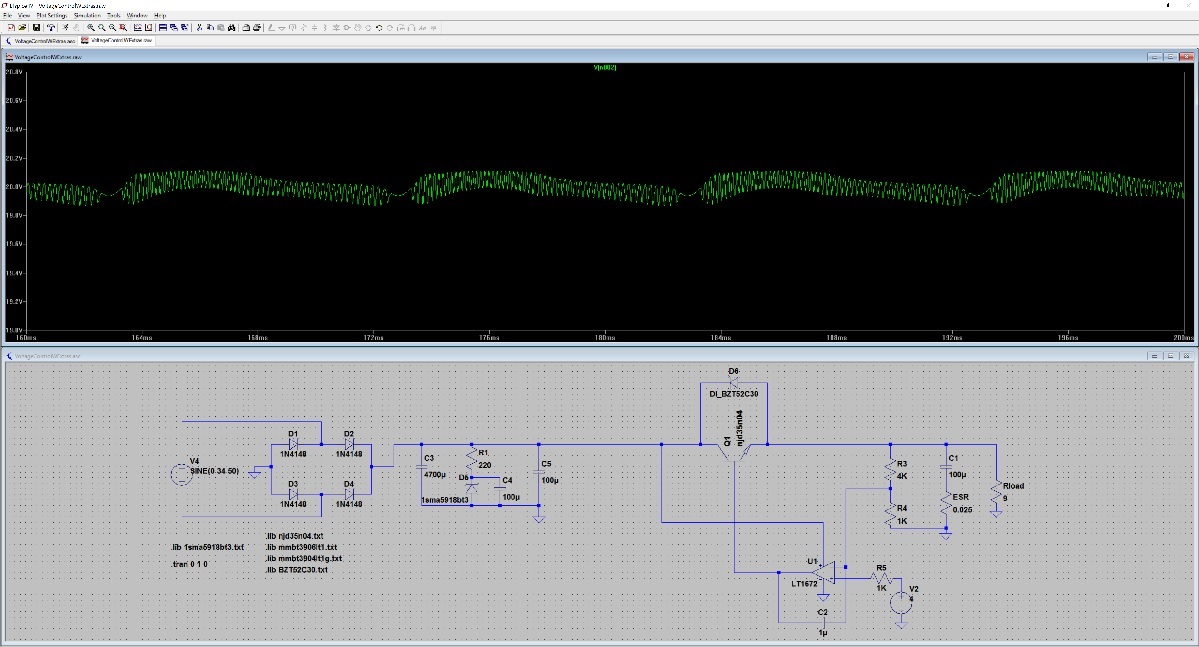
Again, I think that's usable :) Next step, caps. Unless I'm doing this wrong, it seems to handle the low ESR caps well? This is 1uF with 0.001 ohm ESR:


That's the graph that's making me think of adding the second cap in parallel. Next step, I tried to add in the enable transistor. Taking on board the advice about it not working, I went for an NPN between the output of the voltage regulator opamp and the base of the pass transistor. This stopped the circuit from working completely. I'm starting to lean towards maybe just setting 0V on V_DAC to disable, although I don't think this is a great solution... when I simulated it, I still got about 820mV output. I don't want to use a relay on the output but I might keep investigating this and see if there are any other options.

My final test was looking at the low voltage setting with a low resistance load. Based on the 0V test, I gave it 1V output at 9 ohms:


Still not too bad, it's <20 mV throughout.


So that's where I am now. I'd appreciate any suggestions of other tests I can throw at it, otherwise next test will be the second output cap and then on to current control.

To hit all the feedback I haven't answered so far-

mij59 - I agree on the diodes, it just gave me something to work with (rather than a stable power supply). I kind of thought that at the end of the day, individual component tolerances would mean that the only real way to test was to build it and pull out the scope.

Was there a specific thing that Kleinstein mentioned that I didn't catch? The only two I've deliberately stayed away from are the floating regulator and the negative supply for the current control amp - both good ideas, but I think they will over complicate this specific circuit? I did misinterpret the opamp driving the pass transistor but I think I have that fixed now :)

R12 is gone and I've added resistors for the DAC outputs, thanks :) Also not sure what to do on the enable - I'd really like it in there but it depends on whether or not 820mV is good enough for "off". Maybe when I add the current limit it will drain some of that and lower it further - I might just wait and see. Either way, thanks again :)

SteveP - First up, thanks for the app notes, that first one was the "light bulb" moment for converting what I already knew into something that would work. On the pass transistor, it's an ONSemi NJD35N04G Darlington NPN (http://www.digikey.com.au/product-detail/en/NJD35N04G/NJD35N04GOS-ND/1484392). 20V-2A is within the safe DC operator area and as-is (DPAK case) it should function to an ambient temp of around 40 degrees C. I plan to add in extra cooling though - first, I'll give it a patch (>1 square inch) of ground on both sides of the board with thermal vias. I worked out this should give me around 2W (5 degrees) of cooling. Second, I'd like to use a surface mount heatsink (specifically - http://www.digikey.com/product-search/en?mpart=573100D00000G&v=59). This should give me another 3W or so. So running 20V-2A constantly will technically work up to maybe 45-50 deg ambient (at which point I stop to function :D) or the parts will last longer when run at lower ambient temps and power settings. Thanks again!

Kleinstein - I haven't looked at output impedance yet, do you mean of just the regulator or the whole circuit? Is there a figure I should be aiming for? Obviously the lower the better, but what's "good enough" for a simple regulator like this? And yup, the app notes are great, I've found it seems to be a lot about finding the ones that explain concepts in a similar way to how my brain works... Thanks again for all your help :)
« Last Edit: February 07, 2016, 01:15:58 am by braddrew0 »
 

Offline braddrew0Topic starter

  • Regular Contributor
  • *
  • Posts: 79
  • Country: au
Re: Another Power Supply
« Reply #47 on: February 07, 2016, 03:58:20 am »
Quick short update - tried both adding the smaller cap and also a variable resistor as load. Small cap made a very small difference so I'll leave it out. The variable resistor (I used a value of R=9+10000*time) didn't really affect the output much.

I also tried massively increasing the initial filter cap (to 470000uF) but it made very little difference.
« Last Edit: February 07, 2016, 04:10:10 am by braddrew0 »
 

Offline mij59

  • Frequent Contributor
  • **
  • Posts: 693
  • Country: nl
Re: Another Power Supply
« Reply #48 on: February 07, 2016, 06:21:54 am »
Quick short update - tried both adding the smaller cap and also a variable resistor as load. Small cap made a very small difference so I'll leave it out. The variable resistor (I used a value of R=9+10000*time) didn't really affect the output much.

I also tried massively increasing the initial filter cap (to 470000uF) but it made very little difference.

The filter cap is not part of the control loop, so it should not make a difference.

For best performance current sensing use a  floating regulator or use low side sensing.
Add a transistor to Q1 make a darlington.
I you want to use high side current sensing, put the resistor in series with the emitter of Q1.
 

Offline braddrew0Topic starter

  • Regular Contributor
  • *
  • Posts: 79
  • Country: au
Re: Another Power Supply
« Reply #49 on: February 07, 2016, 07:48:24 am »
Yeah I'll definitely go floating on the next one, simpler for this version not to worry about it at the moment. Current sense will be low side. And Q1 is a Darlington - I could only find one Darlington in the LTSPICE library and it wouldn't let me change the model? I just used the NPN picture and a custom Darlington model.

Thanks! :)
 

Online Kleinstein

  • Super Contributor
  • ***
  • Posts: 14197
  • Country: de
Re: Another Power Supply
« Reply #50 on: February 07, 2016, 09:12:42 am »
For the simulation of the regulator you don't need to include the rectifier - the two parts are well separated and can be treated separately. This makes the simulation simpler and faster.

Instead of a Darlington transistor you can use two separate transistors. The choice of using a power transistor in DPAK is poor - this may OK for the first in a darlington configuration, but not to dump the main heat part. Consider at least a TO220 or better even TO247 that are much easier to mount to heat sink. SMD transistors would need cooling through the board and thus usually large GND planes or similar.

The usual OPs don't like driving lower than 50 Ohms load. The simulations might be overly optimistic i this respect, so one should have a resistor between the OP and the transistors. Even if relatively small this will influence the regulation.
Even if you just simulate the voltage loop, you should include the shunt used for current limiting, as this will influence the performance. At some places (e.g. emitter of the output transistor) it can actually help to stabilize the voltage regulation, but in other positions it can also make things more difficult.

You will find out, if a negative supply is needed or wanted. It could make the regulator easier or faster.

The regulator simulated above is very slow - so stability is still relatively easy.

Looking at the output impedance is one way to check for all load impedances. If the phase shift is within the +-90 degree band, the circuit will be stable with any passive (e.g. combination of RLC and DC current sink) load. If not you can see at which frequency and capacitance it can oscillate. The only thing to vary is the load current - e.g. test at high and low currents.
The aim should be something like a 0.5-5 Ohms maximum impedance, that is reached at about 50-500 kHz. At higher frequencies the output capacitor determines the impedance, going down to it's ESR.  Preferably the maximum in impedance is a little flat, not strongly peaked (with output capacitance only).  Towards lower frequencies impedance should go down no faster than proportional to frequency - a stepper curve tends to be unstable. So the regulator output will behave similar to a inductance in the 1-20 µH range.

To check behavior in time domain, using a variable set-point is of limited use. It is better to use a step in load current, e.g. a current source with pulse shape (e.g. 1 µs rise / fall, pulse of something like 10-50 ms, e.g. 1 A to 0.1 A).
 

Offline SteveP

  • Contributor
  • Posts: 24
  • Country: us
Re: Another Power Supply
« Reply #51 on: February 07, 2016, 06:18:32 pm »
Man, good progress!

Couple of comments: Heat: that transistor has an Rtheta j-c of 2.78C/W. Times 40 watts is a 112C temp rise--assuming that *if* the case is kept at 20C (which it can't be), you're at 132C. The max junction temp spec is 150C; you want to run your devices quite a bit lower than that if you want them to last. I typically think of keeping mine to around 100C, though others may be willing to go higher. You will need to mount the pass device to some sort of heatsink: either PCB copper or (much more likely) a chunk of aluminum. The heatsink has a thermal resistance just like the device. You need to add that in to the calc to get the final junction temperature. A non fan-cooled smallish aluminum heat sink has an Rtheta of a few degrees/Watt so now your device can only dissipate half (or less) of your desired 40 Watts.

If you noticed in the first link I gave you there is a comment (near bottom of page 4) that NPN regulators are *unconditionally* stable (Yippee!), so your choice of an NPN device has helped you there. It would be a different story if you tried an N-Fet.

You've done some good testing. Here's the one you're missing: grab a "load" from the device list; define it by clicking on "advanced" in its dialog. Choose "pulse". The dialog will change and allow you to enter some values. "I1" is what the load starts drawing, so put in something like 0.1A; for the second (what it will draw as the pulse) put in something like 1.1A. Use something like .1 seconds for the delay, so you can see what the stable situation is, put in something like .001 seconds for rise and fall times, put in about .1 seconds for on time. Graph the output voltage; what you want to see is that the output voltage stays constant (or very very close to it). You shouldn't see spikes or huge dips just before or after the current changes. Now change the rise and fall times to one microsecond and repeat.

You will want something to compare against. Grab the data sheets for the LM117/317 and the LT3080. In the textual specs you'll see that the LM117/317 is spec'd for 0.1% for load regulation and that the 3080 is spec'd for 1mV. You'll want to be in that range. Then, look at the graphs for "load transient response" (there are also graphs for "*line* transient response"). At the bottom of the *load* transient graph is the change in current demand, the top of the graph is the vreg's response. Notice  how slow the pulse is for the LM117/317 leading/trailing edges-- almost 5uSec. That's because the LM117/317 is pretty poor and if they showed the response for faster edges it would look really really horrible. Compare the graph for the 3080--those leading edges are darned near vertical and the response is quite a bit better. You'll notice dips/spikes at the moment the current changes. Minimizing these is part of the challenge. (Notice that the LM317's response is measured in *volts* and the 3080 is measured in mV--quite the difference!)

Aside from accurate regulation and no spikes, you also want to look at "settle time"--how *fast* does the voltage settle to its ultimate value. This is often 10s of microseconds, although faster is entirely possible. Good commercial power supplies (e.g., HP/Agilent) try to settle to some small percentage within 25usec IIRC.

If you want to play some, make a little test circuit and try a pulse test with an LM317 and an LT3080 (they're both in LT's "Power" folder--the 317 is the LT317A). You'll see a big difference and you'll start to see where your circuit/components fit in. You can decide whether you want to be an LM317 (or worse) or an LT3080 or somewhere in between.

On another subject, the images you attach are really hard for me to read on my machine--kinda looks like you're using something other than LTSpice to do a screen capture and then attaching those?? What most folks seem to do is go under Tools and use "Copy bitmap to clipboard" which makes a high-quality bitmap, then attach that. [The bitmap it makes is from whatever window (plot or schematic) is active]

At this point, my suggestion would be to make sure your pass device/heat sink can really handle the heat (with room to spare). If you can find a way to make it work with the NPN BJT, you'll be ahead of the game. If you have to switch to a mosfet, now would be the time to do it--they get driven (from the op amp) in different ways and they affect the compensation network quite differently.

You're doing great!

--Steve
 

Online Kleinstein

  • Super Contributor
  • ***
  • Posts: 14197
  • Country: de
Re: Another Power Supply
« Reply #52 on: February 08, 2016, 05:28:01 pm »
Usually a lab power supply is not as fast in regulation as these simple regulator chips. The regulator chips are made to work with a reasonable well behaved load, while a lab power supply should work with essentially every possible load. This requires the lab supply to make some compromises that makes them slower. Also the usually very limited power rating of the integrated regulators allows them to use rather fast transistors. It gets really difficult to make a lab supply that fast - even if it works in the simulations, there are parasitic effects (e.g. inductance and inductive coupling) that makes it really hard.

A good guess to get it fast with an external power device, something like an LT1575 would be a choice. But this is not a simple things as layout is critical.
 

Offline SteveP

  • Contributor
  • Posts: 24
  • Country: us
Re: Another Power Supply
« Reply #53 on: February 08, 2016, 07:27:32 pm »
Kleinstein: I do see what you're saying and I somewhat agree. However:

1) The point of this exercise, according to the OP's initial statement, was to *learn*. In my opinion you don't learn by making things really really slow--if you do, you never run into the tough issues in simulation, though you might when you start playing with actual components. I think it's better to hit the issues first in simulation where it's easier to see what's going on and to make changes. In simulation, in other words, you have to make things fast to learn what the issues are for the exact reason that the simulation doesn't (typically) include the parasitic effects you mention. Also, my suggestion was to compare a *simulated* LM317 against a *simulated* candidate design. Apples to apples.

2) To your point that bench supplies typically aren't as restricted in current/voltage as chip voltage regulators, in this case  the OPs design envelope (20v, 2A) puts it squarely within the envelope of the LT3083 and not far from the LM317 (2A vs 1.5A). I am not sure that I agree that chips are not meant to handle the variety of loads that bench supplies must face--the datasheet for the LT308x series doesn't seem to suggest there are any restrictions as long as the voltage, current, and temperature specs are met, though perhaps I missed something.

3) I suspect that even an old design like an HP 3610, 3611, 3612 would not be as bad as an LM317.

4) I ran sims of prasimix's power supply (the .asc files are publicly available). They simmed pretty darned well and it is my understanding that the hardware performs similarly. That may, however, fall under your category of it being "really hard"--he put a lot of work into those boards. 

5) At some point one moves from simulation to the real world. In my view, that's the stage in learning where one considers in detail the issues you mention, as well as others (like models of devices don't simulate accurately, etc.). Before then, when learning, you don't really have the background to appreciate the issues inherent in that step.

In short, I agree that there is a point to consider everything you mention. My belief is that the OP is not yet at that point.
--Steve
 

Online Kleinstein

  • Super Contributor
  • ***
  • Posts: 14197
  • Country: de
Re: Another Power Supply
« Reply #54 on: February 08, 2016, 08:49:27 pm »
Like most lab supplies the old HP3610 is very likely slower in response to load changes than a LM317 with a moderate load. The LM317 is actually quite fast. This can get different with a larger capacitance at the output. The regulator chip likely will not oscillate, but expect quite some ringing with a large low ESR cap.

So my point is, that there is no need to make the first regulator design that fast. If you get 1/10 the speed of a LM317 this could be still an acceptable lab supply - there are supplies that are even slower. There just is no need to get much faster than the commercial designs for the  first try. However the suggestion with a 1 µF integrating cap is to slow to be practical.  Just for learning it's not so bad to start very slow first to make the simulation run stable, check for DC values and only than adjust for higher speed.  The same also works for real parts.

For early designs it was a common way of adjustment to start slow first, check for DC performance, then make is faster until oscillating and than adjust back by a certain factor for the final setting.  This is somewhat similar to classic tuning of a PID controller by the Ziegler Nichols method.
 

Offline SteveP

  • Contributor
  • Posts: 24
  • Country: us
Re: Another Power Supply
« Reply #55 on: February 08, 2016, 09:43:42 pm »
I think we are talking at cross purposes. You are talking about *designing a real thing* and I am talking about *learning*.

We do all sorts of things when we learn, so that we *can* learn. We assume that gravity is constant or that air has no effect on a falling object. We treat op amps as "ideal". Then, when we have the basics in our heads, we can consider more realistic conditions.

If you don't, at some point, push the bounds of the envelope, you never learn that there *is* an envelope and you never know where those bounds are. I didn't learn very much about regulation until I fought with oscillation. If you never create a circuit which oscillates, how will you ever learn about it? I agree that you want to get to a point where it does *not* oscillate, but my point is that when learning about regulation you *do* have to fight that battle, and that a good way to create that battle is to try to make something fast.

The OP has already created a circuit that is stable. I think it is now time for him to learn about oscillation. Of course, that's his choice, but I think it's an absolutely necessary part of learning about power supplies.

In fact, one way to look at the essence of regulation is to see it as a balancing act between speed, accuracy, and stability (as well as the usual other issues). In my opinion, until you've dealt with that balancing act, you haven't really learned the deeper issues of regulation.

--Steve

P.S. To Brad: I feel totally weird talking about you behind your back like this; hope you don't mind the meta discussion :-)
 

Offline braddrew0Topic starter

  • Regular Contributor
  • *
  • Posts: 79
  • Country: au
Re: Another Power Supply
« Reply #56 on: February 09, 2016, 08:14:31 am »
Not at all, I appreciate both of you taking the time to help me. :) And you both have valid points - this design is a learn-what-I-don't-know type, but I do want an understanding of how something more complex works for future designs. I'm trying to absorb as much of what you both say as I can - a lot times I have an idea of where I want to go but not how to get there. The detail you're both providing is great :)

There's a lot of information in your last posts (and I can't believe I spent so long trying to add a variable load without adding a load that's variable....  |O :D). It's going to take me a few days to absorb it all and run my next tests. In the meantime, I want to briefly touch on the cooling side.

What I've tried to do with my designs is add in things which will work, but aren't recommended. A lot of recommendations here are subjective - not to take away the fact that they're based on considerable levels of experience which I don't have - my goal is to gain that experience by trying things that aren't necessarily the "right" way. As an example, my last design I decided to use 0603 components for all of the resistors, caps and LEDs. I didn't have a space requirement (in fact the board was bigger than if I used through hole - I wanted room to solder :) ) but I wanted an appreciation of the hassle associated with using them, so next time I come up with an idea that "requires" 0603 I'll have an appreciation of how hard that is to do and whether it's worth it. And I learnt that all the advice on here is absolutely correct, 0603 is a pain to solder! It's not a case of being difficult, it's just really fiddly with pieces sticking to the soldering iron and half a dozen 0.1uF ceramics that are probably in the vacuum cleaner by now... regardless, I now know what the cost is of using 0603 and I'll think harder before I use them.

So in a similar way, one of my objectives here was to use an SMD pass through device. And I totally get that it's not recommended and cooling will be a major issue. I have a couple of designs in mind for later where I'm not going to have a real choice on SMD or not, so I wanted to use this as an excuse to learn about properly cooling SMD (hence why I already had an answer for you when you asked about cooling before - it's definitely forefront in my mind :) ).

So saying that, I thought about a better way to attack this today and I'm leaning toward a software current limit. I originally came up with 2A based on a 5V 2A charger - enough to implement a charging circuit one day if the design is suitable. I don't have any requirement to hit 20V @ 2A - I think I will use 20V and I think I will use 2A but not both at the same time (at least not in the near future - and now I'm learning how to make something that will exceed that :) ).

So what I'm thinking is a software current limit to a max of 2A @ 10V, linearly decreasing to 1A @ 20V. That gives me a maximum of 20W of power. I don't anticipate that I'll operate it to these limits, but I want it to obviously be safe to do so. I'm still planning to use both a cooling ground plane and a surface mount heatsink. So by the datasheets, I have:

Rtheta-JC = 2.78 deg/W
Rtheta-JA = 71.74 deg/W
Heatsink Thermal Resistance = 15 deg/W
Tmax - 150 deg C

Does this mean that this device will run at approx 1500 degrees above ambient at 20W? How do I take into account the effect of the heatsink? I can't wrap my head around how 10W of power dissipated on one device will correlate to the same cooling effect as 10W of power dissipation on a different device, if they're both made out of different materials?

Is there any way to make the SMD device work with these limitations?

Thanks again guys, really appreciate the help :)


Offline mij59

  • Frequent Contributor
  • **
  • Posts: 693
  • Country: nl
Re: Another Power Supply
« Reply #57 on: February 09, 2016, 08:43:34 am »
The thermal resistance Rtheta-JA = junction to air, so without the use of a heat sink, check the data sheet how this defined.
The overall thermal resistance has to be much lower,  even with a total thermal resistance 17.78 C/W the temperature rise will be 355 C @ 20 W
 

Offline braddrew0Topic starter

  • Regular Contributor
  • *
  • Posts: 79
  • Country: au
Re: Another Power Supply
« Reply #58 on: February 09, 2016, 10:01:18 am »
OK, that makes sense - so rough numbers realistically you wouldn't want to pass more than about 3W... even with forced air (brings it down to 11 deg/W) you'd probably want to limit to 4-5W. With a D2PAK the non-forced case is around 11 deg/W so same limit, but if you force air through it (600 LFM) that drops to 3 deg/W... I'd say 20W would be technically achievable here provided you found a D2PAK with similar theta jc and you included a decent sized fan, but that's probably pushing the limits of what I wanted to do here - I guess that means I'll be switching to through hole...  :-//

Thanks again for the help :)
 

Online Kleinstein

  • Super Contributor
  • ***
  • Posts: 14197
  • Country: de
Re: Another Power Supply
« Reply #59 on: February 09, 2016, 12:40:41 pm »
Calculating the efficiency of heat sinks is a little tricky. In first approximations there is a heat resistance rather similar the electrical resistance. However the transfer from the heat sink to air depends on the conditions, like air flow, orientation and surrounding. Also heat can drive there own convection flow - this makes thermal resistance nonlinear. There are approximate formulas on how effective cooling through the board is. This may work for 2 or 4 W but not really good at 20 W. If you want, one can solder a TO220 like a SMT part.

As a rule of thumb it is a good idea to use only about half (maybe 2/3) of the P_tot rating of power transistors. This makes cooling easier, as the case can then be at up to about 80 C as opposed to 25 C for the full P_tot rating. With a reasonable heat sink the temperature should be below 60 C, so you avoid burns form touch. Transistors are not that expensive any more, so it can be worth using a larger transistor instead of a larger heat sink.

Current liming usually should be fast, as one purpose is to protect the circuit and the supply. So a software only solution is not that great and would need at least a fast backup to protect the regulator.

For a linear supply using a single transformer tap, the maximum heat loss occurs at a short with maximum current. The power will be raw voltage times current. So for a 20 V 2 A supply this could be up to about 50 W (assuming about 25 V raw voltage) - reducing the current limit at high voltage does not change anything. If at all the opposite helps, this is called foldback current limiting - the maximum current gets smaller at low voltages. Many chip regulators like the LM317 use foldback, but lab supplies usually not, as this may cause instabilities with some loads.

Its a different thing if a second transformer tap is used - this reduces the maximum power loss, except for short transients. At low power like here using a second tap is not very common. 50W  is still easy to cope with, with a single transistor like 2N3055.
 

Offline braddrew0Topic starter

  • Regular Contributor
  • *
  • Posts: 79
  • Country: au
Re: Another Power Supply
« Reply #60 on: February 10, 2016, 08:41:10 am »
This cooling thing is still getting me - even if I keep below around 3 deg/W total thermal resistance, under normal max conditions that would be a temp rise of 120 deg (giving 30 degrees ambient max, assuming I'm happy to let it get damaged at 30.1 ambient). But to even get to 3W unforced, I need less than around 2 deg/W thermal resistance on the heatsink. Digikey (http://www.digikey.com/product-search/en/fans-thermal-management/thermal-heat-sinks/1179752?FV=fff40012%2Cfff80068%2Ce68004c%2Ce68004d%2Ce680053%2Ce68006c%2Ce68006d%2Ce6800c6%2Ce6800c7%2Ce6800cc%2Ce6800d0%2Ce6800d2%2Ce6800d3%2Ce6800d4%2Ce6800d6%2Ce6800d7%2Ce6800d8%2Ce6800da%2Ce6800db%2Ce6800dd%2Ce6800de%2Ce6800df%2Ce6800e0%2Ce6800e1%2Ce6800e2%2Ce6800ea%2Ce6800f4%2Ce6800f5%2Ce6800f6%2Ce6800f7%2Ce6800f8%2Ce6800f9%2Ce6800fa&mnonly=0&newproducts=0&ColumnSort=1000011&page=1&stock=1&pbfree=0&rohs=0&k=&quantity=&ptm=0&fid=0&pageSize=25) gives me a bunch of options, but they start at around $15 and go up pretty quickly from there...

So I guess this is what you were talking about Steve, with a BJT 40W isn't really achievable without forced air? Are there any other tricks to employ here?
 

Offline braddrew0Topic starter

  • Regular Contributor
  • *
  • Posts: 79
  • Country: au
Re: Another Power Supply
« Reply #61 on: February 10, 2016, 09:43:24 am »
Sorry should clarify - any tricks that don't involve forced air or paralleling transistors?
 

Offline mij59

  • Frequent Contributor
  • **
  • Posts: 693
  • Country: nl
Re: Another Power Supply
« Reply #62 on: February 10, 2016, 11:58:53 am »
Sorry should clarify - any tricks that don't involve forced air or paralleling transistors?

Paralleling transistors makes no difference, you’ll need a preregulator.
 

Offline SteveP

  • Contributor
  • Posts: 24
  • Country: us
Re: Another Power Supply
« Reply #63 on: February 10, 2016, 02:27:57 pm »
He he, welcome to power supply design :-)

Big picture comment: to design a power supply means juggling heat, voltage, current, stability, accuracy, speed, sometimes cost, and functionality, among other things. It's a lot to juggle.

I get that you like to push the envelope. That's great! One of the great things about at least *investigating* something others don't usually do is that you will find out why they don't do it. Then, if you are lucky, you'll think outside the box and come up with something others haven't thought of. I think that's called "progress" :-) If you are not so lucky, you'll have to relax a constraint or two, but at least you'll know *why* you're doing so. You will also gain a real appreciation for just how great some of the designs you'll see really are (and how crappy some others are).

In dealing with heat, there are the usual suspects:

1) paralleling devices *does* work--there are lots of commercial PSUs that have paralleled a few devices; the HP 36xx series I mentioned earlier paralleled four pass devices. (I mention that series because the schematics are available online.) You still need a (usually big) heat sink, but it spreads the load across more heat sink area and each device (obviously) needs to dissipate less heat. The issue with paralleling devices is that you need to take steps to get them to share the current equally; the resistance of some devices (BJTs) drops as they warm up, so they pass more current which heats them up more, and you get thermal runaway. If you try to parallel them, one will inevitably carry a bit more current than the others, so it heats up more, starting the thermal runaway scenario. Mosfets typically *raise* their resistance as they heat up, so you don't tend to get thermal runaway. There are techniques for dealing with BJTs in parallel, but that's outside my area of knowledge, so you'd have to research that one on your own. Mosfets are paralleled all the time--for example, the controllers for electric vehicles (many KW) have been doing it for years.

2) You can switch to a pass device with a lower Rtheta. Rtheta isn't a searchable characteristic on websites like Digikey, but you can use Power as a surrogate. Mosfets typically have a lower Rtheta, sometimes *very low* (.05 W/C is the lowest I've seen). I don't recall what the lowest Rtheta is for BJTs. The 3055 (but not SMD) mentioned by K is about 1.52 W/C in the TO-3 case and the datasheet claims you can run it at 200C, just to give you a reference point ( was looking at the one from ON-Semiconductor).

3) There are pre-regulators and there are pre-regulators. I agree wholeheartedly with the decision to not tackle a "real" pre-regulator for now, but you can use a simple one:  the "high low" switch. Transformers today typically do not have a bunch of taps like they did in "the old days". However, many transformers *do* come with one "tap"--the outputs can be put in series or parallel. Use a DPDT switch to switch the transformer leads from series to parallel when you want low voltage--it will cut the drop across the pass device(s) by half which cuts the power dissipation by the same amount.

4) Don't know if you've gone down this path yet, but you can stitch together (with vias)  top side and bottom side PCB copper to get increased dissipation. I've never gone that route, but lots of designs for other things do, so the info is likely out there regarding Rtheta of that construction. I suspect it wouldn't be sufficient for 40W, however. You could also try to solder some small copper "fins" to the SMD's pad to decrease Rtheta.

5) You could solder an SMD pass device to a sheet of copper and get a lower Rtheta for that vs. what you'll get on a PCB, but I doubt you'd get as low as you need to and it probably defeats the whole reason you're considering SMD in the first place. Just to continue the thought, however, soldering to copper sheets is done with lighting LEDs all the time. There are online calculators for *simple* (flat plate) heat sinks. You can also search Digikey for heatsinks to get a *rough* idea of how much heat can be dissipated by the various types, but the Mfrs often use extremely optimistic numbers; I'm not a passive heatsink guru (though I've done my share of heat calcs for solid bars of various materials) but I'd suggest cutting them by half. The idea here being that you'd make a copper heatsink like an aluminum one; you'd use the Rtheta of the commercial aluminum one to guide your design of the copper one. You can also use the flat plate of copper as a heat "spreader" and fasten that to a larger aluminum heat sink.  In the end, you'd probably have to do a prototype of just the transistor and see how hot it really gets. The bottom line, of course, is that PCB copper can only dissipate a certain amount of heat--period.

5) forced air; yeah, I know :-(  But it really gets rid of a lot of heat....

Of course, you can use a combination of the above. Sometimes that can get you where you need to go without making too many sacrifices. E.g., a high-low switch and a different pass device. Or you find a pass device with a higher junction temperature rating. And/or you decide to run right at the junction temp rating (*not* recommended for a whole bunch of reasons).

You may find yourself making some unpalatable design decisions here....as I said at the outset, I went back and forth on pass devices many times before I settled on one. Part of it was heat--mosfets were great for heat, terrible for stability. BTJs the opposite. When I thought I had heat licked using mosfets, I fought instability until I went nuts. Then I went back to BJT and fought with heat until I went nuts. I looked at *a lot* of data sheets :-)

--Steve

Edit: corrected Rtheta j-c for 3055 due to misreading the datasheet....
« Last Edit: February 10, 2016, 05:37:08 pm by SteveP »
 

Online Kleinstein

  • Super Contributor
  • ***
  • Posts: 14197
  • Country: de
Re: Another Power Supply
« Reply #64 on: February 10, 2016, 04:10:06 pm »
With just 40 or 50 W it is possibly to use a single BJT or suitable MOSFETs. You just need to choose one that is powerful enough and has a low internal thermal resistance. Something like a 2N3055 (TO3 case) or TIP3055 ( To218) will do it. With a smaller transistor you need a larger heatsink.

Paralleling BJTs is relatively easy, with just resistors at the emitter. Paralleling MOSFETs works well in a switching application but is more difficult in a linear application like the linear regulator. Here resistors at the source pins are needed which usually need to be larger than with BJTs. In addition the MOSFETs need to be matched.
 

Offline braddrew0Topic starter

  • Regular Contributor
  • *
  • Posts: 79
  • Country: au
Re: Another Power Supply
« Reply #65 on: February 11, 2016, 05:42:54 am »
And it just clicked on the drive into work this morning that I'm making the same mistake I made before with the 7805 temp calculation - I've been looking at power through the transistor = heat where I should have been looking at power dropped = heat... That means I really need to pass 34V * 2A = 68W....  :palm: It means a lot of your comments make more sense now, like why low voltage high current is the worst case...

Kleinstein, I did look at that one - unless my maths is wrong, I couldn't cool it to a reasonable temp even with 40W? I get theta jc as 1.52, so 40W = 60.8 above ambient, but then the heatsink kills me - the first <$10 heatsink for TO-3 has a thermal resistance of 5 deg/W (http://www.digikey.com/product-detail/en/500403B00000G/HS264-ND/373756), so that would add 200 deg on it's own, giving ambient + ~260deg at max power?

Even going top of the line at $156 for the heatsink (http://www.digikey.com/product-detail/en/HS04/598-1472-ND/1762106) it has  thermal resistance of 0.95 deg/W - so my 68W would sit at 170 degrees above ambient... ouch!  :o

I'm starting to lean towards paralleling the output to increase the current. That means I can drop down to something cheaper like a 2N6045 (http://www.digikey.com/product-detail/en/2N6045G/2N6045GOS-ND/918259) with a reasonable heatsink (http://www.digikey.com/product-detail/en/530002B02500G/HS380-ND/1216384). That's about $2.50 per couple and if I split the 68W over 4 I get a max temp of about 73 above ambient on each - so with 30 ambient that gives me about 50 degrees flex in case one of the devices heats faster than the others?

And I will address all the points you've all made - I've read them all, just trying to process some of it. Thanks again for the help :)
 

Offline mij59

  • Frequent Contributor
  • **
  • Posts: 693
  • Country: nl
Re: Another Power Supply
« Reply #66 on: February 11, 2016, 05:59:45 am »
When sourcing components check several vendors.

For heat sinks you use something like this http://www.reichelt.de/Luefteraggregate/LAM-3100-12V/3/index.html?&ACTION=3&LA=2&ARTICLE=75424&GROUPID=3751&artnr=LAM+3100+12V  .
You'll need some airflow in the enclosure anyway.
 

Offline braddrew0Topic starter

  • Regular Contributor
  • *
  • Posts: 79
  • Country: au
Re: Another Power Supply
« Reply #67 on: February 11, 2016, 09:54:58 am »
Thanks mij59 - I think I'm going caseless for this one but I've bookmarked the site for future reference :)

On another topic, if I parallel the BJTs, do I need to use resistors on each of the emitters?
 

Offline mij59

  • Frequent Contributor
  • **
  • Posts: 693
  • Country: nl
Re: Another Power Supply
« Reply #68 on: February 11, 2016, 11:31:42 am »
Thanks mij59 - I think I'm going caseless for this one but I've bookmarked the site for future reference :)

On another topic, if I parallel the BJTs, do I need to use resistors on each of the emitters?

If the transistors are exactly the same no, but they are kind a hard to find in the wild.
 

Offline SteveP

  • Contributor
  • Posts: 24
  • Country: us
Re: Another Power Supply
« Reply #69 on: February 11, 2016, 05:24:19 pm »
Wait, why is it 34 volts? Last I saw it was 20v. If you want an output voltage of .001 volts, you'd drop about 20v * 2A = 40 watts. What am I missing?
--Steve
 

Offline braddrew0Topic starter

  • Regular Contributor
  • *
  • Posts: 79
  • Country: au
Re: Another Power Supply
« Reply #70 on: February 12, 2016, 02:24:32 am »
Steve my initial input was 18VAC which I could smooth to the range 26-25V using 40,000uF of input capacitance. I changed that to 24VAC in with 4,700uF which gives me 34-28V (both assuming 2.5A draw which is 2A + "some" for regulator, uC, overswing, etc). So my max input is 34V and max drop would be 34V @ 2A = 68W (although this obviously isn't constant).

My original plan called for 24V @ 2A max (hence 26-25V) but I got rid of that early because I wanted to cap the power at 40W. Now I can see the high end doesn't really matter (except pass device drop) so I may bring that back in.
 

Offline braddrew0Topic starter

  • Regular Contributor
  • *
  • Posts: 79
  • Country: au
Re: Another Power Supply
« Reply #71 on: February 12, 2016, 02:54:59 am »
And sorry, one more random thought on that power calculation - at low current draw there would be minimal ripple, which means at (for example) 0.001V and 0.001A the pass device would be generating a solid 68W of heat.
 

Offline SteveP

  • Contributor
  • Posts: 24
  • Country: us
Re: Another Power Supply
« Reply #72 on: February 12, 2016, 03:26:44 am »
OK, got it, thanks. I just plain missed the part where you earlier explained about the ripple. Yeah, 68 watts is harder than 40 :-)

While you're thinking about heat, here are a couple of more things you may want to consider...

1. Once you get the heat out of the device and into the heatsink, you need to (obviously) get it from the heatsink to the air. But where is the air? You probably don't want it *inside* the enclosure (I know, for this first version there isn't an enclosure, but *someday* there probably will be so you might as well think about it a little now...) for a couple of reasons:
  a) you don't want to bake your other components. Yeah, you'll have the usual plethora of ventilation holes, but the air inside will still be hotter than outside.
  b) you want the coolest air possible hitting your heatsink because what matters is the difference in temperature between the heatsink and the surrounding air.

So you'll probably want a design/devices that allow at least a portion, if not all of, the heatsink to be outside the enclosure.

2. You may or may not have noticed, but the part of your pass device that attaches to the heatsink is *live*. That makes the heatsink live and if the heatsink is outside the enclosure, you may not want the heatsink to be live. This means you'll need an electrically insulating material between the device and the heatsink. Problem, is, those are also *thermally* insulating which means there's one more bit of thermal resistance you have to account for. If you search places like Digikey for "thermal pad" you'll find what you're looking for. In the TO-220 size, they seem to range from about 0.35C/W up to about 0.75C/W. Doesn't seem like a lot until you multiply it by the 68 Watts. This will tend to drive the cost of your heat sink up, since it has to be more efficient (i.e., bigger).

If you haven't figured this out, heat is a major driver of linear power supply design :-)
--Steve
 

Offline braddrew0Topic starter

  • Regular Contributor
  • *
  • Posts: 79
  • Country: au
Re: Another Power Supply
« Reply #73 on: February 12, 2016, 04:55:45 am »
To be fair, heat only started becoming an issue when I started doing the calculations correctly...  :D

Good points Steve - I knew about the thermal pads but didn't consider you'd have to take them into account, so that's a good learning point. I remember about 20 years ago from building computers in my teens that CPU heatsinks work significantly better with good quality thermal paste - that's one thing I was planning to do, although I assume the manufacturers figures are based on the best case scenario, so that's probably only stopping any more loss. I think the next design (and anything in an enclosure) will definitely be based on a switching pre-reg - I do want to get this one built simply though, just to show myself that what looks good on paper actually works (or doesn't....)

So with that, I think I have a plan. I think I'll switch back to 18VAC in, with the 40,000uF filters. If my math is correct, that's 25.46-24.83V @ 2.5A. If I use two NTP5864N N Channel MOSFETs (http://www.onsemi.com/pub_link/Collateral/NTP5864N-D.PDF) with the Aavid non-forced heatsink from before (http://www.digikey.com/product-detail/en/530002B02500G/HS380-ND/1216384) that's a total thermal resistance of 4deg / W. So each device would need to drop a maximum ~26W, which is 104 deg. This is hot, but still workable in a normal (up to 30 deg) ambient environment. As a bonus, the two MOSFETS will naturally equalise current so I'm not as worried about one getting hotter than the other (like I was before). I should mention as well that the NTP5864N is good to 175 deg :)

For bonus points as well - the data sheet specifies a max Rds of 12.4 mohm. With a 100 mohm pass resistor, then at 2A I could expect a ~225mV voltage drop, which means I can (maybe) regulate to 24V!  :-+
« Last Edit: February 12, 2016, 04:58:29 am by braddrew0 »
 

Online Kleinstein

  • Super Contributor
  • ***
  • Posts: 14197
  • Country: de
Re: Another Power Supply
« Reply #74 on: February 12, 2016, 01:47:33 pm »
Using two small MOSFETs in parallel is a poor decision: They would need rather large source resistors (e.g. 0.5-1 Ohms)
to make them share the load. Thus the voltage drop will be rather large. At 2 A and 25 V raw supply you could get away with just one larger MOSFET (e.g. IRFP240) or BJT.

Using MOSFETs also needs something like 3 V higher voltage to drive the gate.
 

Offline mij59

  • Frequent Contributor
  • **
  • Posts: 693
  • Country: nl
Re: Another Power Supply
« Reply #75 on: February 12, 2016, 03:07:50 pm »
As a bonus, the two MOSFETS will naturally equalise current so I'm not as worried about one getting hotter than the other (like I was before). I should mention as well that the NTP5864N is good to 175 deg :)
For bonus points as well - the data sheet specifies a max Rds of 12.4 mohm. With a 100 mohm pass resistor, then at 2A I could expect a ~225mV voltage drop, which means I can (maybe) regulate to 24V!  :-+

Equalising properties only apply when the mosfets is used as a switch, when used in a linear power supply the mosfets are  used in the linear mode.
At a junction temperature of 175 C the maximum drain current is zero.
The maximum Rds is not important the mosfet is not used as a switch.
 

Offline SteveP

  • Contributor
  • Posts: 24
  • Country: us
Re: Another Power Supply
« Reply #76 on: February 12, 2016, 04:31:55 pm »
[Others chimed in before I finished typing....but here it is anyway...]

You seem to be having fun! Glad to see you've wriggled out of the grasp of the heat demons (at least temporarily). Here are a few comments:

1) When you start cutting things a bit close, you need to take into account things like the fact that mains voltage isn't always on spec; sometimes it's less, sometimes it's more. Your 18VAC may be a bit higher making your drop a bit larger. I used 10% in my calcs, just to be safe. Even 5% gives you a 26.8v drop * 2.5 A = 67Watts / 2 = 33.5 W * 4C/W = 134C + 30C = 164C/175C = 92% of spec. That's far too close for my comfort. There's a general rule of thumb that says for every 10C drop, you double the lifetime of the component. The mfrs don't spec *lifetime* at Tjmax, so you're kinda guessing on that one. But as I indicated before, I try to run my devices fairly cool.

2) You're talking about running mosfets in parallel. It *can* be done, but you're wandering into a bit of a snake-pit. Just from the point of view of heat (that is, leaving aside the issue of controlling them in a feedback loop), the problem is that below a certain threshold they *don't* share current equally (I had forgotten this until Kleinstein mentioned switching vs. linear mode back a few replies). The explanation can be found here:

http://www.infineon.com/dgdl/Infineon--AN-vNA-NA.pdf?fileId=db3a30433e30e4bf013e3646e9381200
(if the link doesn't work, go to Infineon's website and search for "AP99007")

Still, HP ran 4 IRF440 in the 3610 with no resistors (that I could find in the schematic), so maybe with enough derating it isn't as hard as it seems.
Edit: oops, found them. 10 ohms, but only one resistor per *pair* of FETs.

Anyway, let's do a heat calc in reverse, assuming a max jct temp of 175C and assuming you don't run it at more than 150C (86% of max--still pretty high...):

150C -30C (ambient) = 120C / 70W (round numbers) = 1.7 Rtheta (total) C/W - .5 C/W (Rtheta device) = 1.2 C/W Rtheta heatsink. I did a quick digikey search (US) and about the cheapest I could find was $15.

So now you need to find an n-fet that:
1) Has a Tjmax of at least 175C
2) Handles 300W (which is an indirect way of finding one with an Rtheta of 0.5C/W)
3) Doesn't have much more than about 3000pF of input capacitance (more on that later)
4) Has a SPICE model you can get your hands on

(4) is tough...and you definitely want to be able to sim them. I did a quick search and didn't quickly find one that I could find a spice model for. The 175C reduces your selection by quite a bit, but that's kind of forced on you because of your volts*amps decision.

Without trying to push you in a particular direction, I did the following calc:

150C Tjmax running at 125C (83%) - 30C (ambient) = 95C / 1.7C/W total Rtheta = 56W  = 25V * 2.24 Amps. That's not much of a reduction in your volts/amps envelope.

Or....you could use a CPU cooler (with a fan) ....really good Rtheta and small ones are cheaper than big heat sinks....

=================
Now about that input capacitance...

I won't try to go into chapter and verse here, but mosfets have capacitance built into them, some more than others. Very roughly speaking, the bigger the die, the more the capacitance. OK, pick one with a small die, right? You'd like to, but heat dissipation (Rtheta) is proportional to die size! So, if you want to be able to handle a lot of power, you end up with a bigger die which means more capacitance.

So what's the big deal with capacitance? One way to look at it is that it slows down the response of your feedback loop. A slow feedback loop means that things get out of whack for a longer time (thereby being more out of whack) before the control mechanism can catch up and correct the situation. It also makes it harder to create a compensation network for the opamp because it creates a low-frequency pole (or moves an existing one further down in frequency). Finally, if your PSU has (or will have) a "mute" or output enable/disable switch, then you can get a big spike at turn-on if the fet has a lot of capacitance.

If capacitance weren't an issue, you could just go for a super-low Rtheta and be done with it. Sadly, it is an issue.

--Steve

« Last Edit: February 12, 2016, 05:47:48 pm by SteveP »
 

Offline braddrew0Topic starter

  • Regular Contributor
  • *
  • Posts: 79
  • Country: au
Re: Another Power Supply
« Reply #77 on: February 12, 2016, 07:57:19 pm »
Steve why 2.5A? I was only using 2.5A for my ripple calculations because I had 2A through the pass device but 500mA set aside for he uC, display, etc... which shouldn't go through the pass device?

OK, one more try... what about MJ11028 (http://www.onsemi.com/pub_link/Collateral/MJ11028-D.PDF) which has a theta jc of 0.58 and this heatsink from Wakefield Vette (http://www.digikey.com/product-detail/en/423K/345-1050-ND/340346) with a thermal resistance of 0.96 non-forced? That's a total of 1.54 deg/W, so at 68W it's a rise of approx 105deg... the darlington is good to 200c, so even adding ambient (and say a 10-20% load increase) I'd still be well below the max?
« Last Edit: February 12, 2016, 08:53:35 pm by braddrew0 »
 

Offline braddrew0Topic starter

  • Regular Contributor
  • *
  • Posts: 79
  • Country: au
Re: Another Power Supply
« Reply #78 on: February 13, 2016, 12:35:04 am »
OK working on the assumption of a single MJ11028 I spent a few hours this morning running simulations. The first thing I noticed was that it seems "slower" than the last device which kind of makes sense - I'd imagine a 300W TO-3 would have more capacitance than a 70W DPAK but this information doesn't seem to be in the datasheets? The integrating cap of 1uF only gave 5 degrees of phase margin and there was noticeable (about 20mV) of ripple on a simple 100 ohm load.

I've played around with this, but also the big thing I worked on was output impedance. The original circuit gave about 38 ohms at around 60Hz - which is a fair cry from 5 ohms at 50kHz (which is the easier end of the range you gave me Kleinstein). I changed the value of a lot of components, but the best compromise I could come up with was 10.7 ohms at 160Hz. I could get lower by changing the resistor divider, but it required significant capacitance on the integrator (5uF+) which gave an unacceptable time to decrease voltage (20V-0V took > 5s). I could also move the peak to a higher impedance by changing the output cap, but this gave extremely sharp peaks, and started introducing multiple peaks rather than the "smooth" curve I ended up with. Best case, I still couldn't get it much higher than 1kHz, and that gave me a completely messed up looking response. Again, I'm putting this down to a "slow" pass device.

So here's what I ended up with, and a few results.


This is the circuit - please note the picture looks like an NPN but the model is a darlington (had a few issues with getting it to display the correct picture). The output cap is based on a real device (panasonic low ESR 100uF cap) and I've added in the current sense resistor.


This is the transfer function. I spent a bit of time trying to smooth out that second peak, and it looks reasonable to me. There's about 25 degrees of phase margin here - I found if I dropped the cap much lower, it would raise the peak on the right which would give me two 0dB values - the worst one being completely unstable (220+ degree phase shift).


This is the output impedance. Like I said before, it's about 10.7 ohms at 160Hz. Phase is between +/- 90 deg across the range so should be stable for all loads.


This is driving a low ESR cap (1uF, 0.001ohm). It doesn't take too long to reach max voltage and it's rock solid once it gets there.


For stamps, I looked at 0V output. Much better than last time, which I assume is from the resistor on the output of the opamp.


This is a step input from 0V to 20V. As expected, it's very similar to the low ESR case.


This is a step input from 20V to 0V. This is the one that would blow out with higher values of capacitance on the opamp. This is much more stable.


And lastly, this is a pulsed load. I went 1mA up to 2A, switching every 10ms. That's a maximum of about 20mV over/undershoot.


So that's where I'm at now. For my purposes, unless there's something I've overlooked, I'm pretty happy with where it is here. I get that it's probably not the "best" possible design, but it's stable, it'll do what I want it to (I think) and most importantly it won't explode.... I think :)

So next step is adding the current limit right? :)
« Last Edit: February 13, 2016, 12:39:47 am by braddrew0 »
 

Online Kleinstein

  • Super Contributor
  • ***
  • Posts: 14197
  • Country: de
Re: Another Power Supply
« Reply #79 on: February 13, 2016, 09:24:29 am »
The large transistor might be relatively slow (can't see anything in datasheet).  It's also a quite large one - two smaller ones (e.g. TIP3055 or similar - still not fast) could be cheaper and more choice. Having a small resistor at the emitter also often helps to improve stability - so the resistors needed for current sharing are also helpful.

The resistor from the OP to the transistor is rather large - this could be a problem with such a large transistor.

To protect the transistor from excessive negative base-emitter voltage, a diode from base to emitter can help.

Normally one would have the divider higher impedance, by a factor of 10-100. This would also bring the integrating capacitor to the more normal range.

One can also improve phase margin by adding a RC series combination in parallel to R3. Though normally this is not needed with this type of regulator.
 

Online blackdog

  • Frequent Contributor
  • **
  • Posts: 739
  • Country: nl
  • Please stop pushing bullshit...
Re: Another Power Supply
« Reply #80 on: February 13, 2016, 01:58:33 pm »
Hi braddrew0,

You must be kidding...
And R6 = 1K
R3 720 Ohm, R4 180 Ohm.
C2 = 1,2uF  |O   :-DD


The OpAmp  |O  :-DD
Max 1.2mA output current.

You've done almost everything wrong, how is this posible.

OK, now the help :)
We start with R3 and R4, make them 10x the value.
C2 = 330pF to start with.
The opamp, try LT1007
R6 = 150 Ohm

Also place a capacitor of 100uF between the collector and R2.

Play with C2 and the capacitor on the output C1, C1 average value = 50uF/Ampere output current.
If you need far more for a stable designs, than adjust C2 to 470 a 560pF.

You need about 1mA current from the opamp output for 2-Ampere output to de load.
I do not know how much current you need and how much dissipation, but several TIP142 transistors is normaly a better solution.
Each with its own base and emitter resistor.

I hope tho see results from you, and think about your circuit, wy the value's are wrong, you will learn a lot of it :-)

Kind regarts,
Blackdog

Necessity is not an established fact, but an interpretation.
 

Offline braddrew0Topic starter

  • Regular Contributor
  • *
  • Posts: 79
  • Country: au
Re: Another Power Supply
« Reply #81 on: February 13, 2016, 11:33:19 pm »
Thanks Kleinstein - what range is "small" for the emitter transistor? I'll start at 1 ohm and see what the results are like. As for the BE protection diode, I hadn't seen that one before, so thanks - I'll add something in. I had the divider at 4k/1k but lowered it to try and drop the output impedance. Good tip on the extra RC network- I'll keep that one in my back pocket for the next design. And I'll put something together with parallel BJTs today. Thanks again :)

Hi blackdog - thanks for the input! Nope, I'm not kidding, I'm just trying to learn :) As to how I ended up where I ended up, it can be pretty much summed up as:

* The pass device was the only one I could find that would drop 68W without spending $150+ on a heatsink
* As you say, I planned on 1mA of current for 2A so I didn't see the 1.2mA max current of the opamp as a limitation
* I started with 4K/1K as the divider, but this gave me about 38ohm output impedance - I dropped them down progressively until I hit the values on that schematic, which gave me closer to 11ohm
* Lowering R6 made the "peak" of the impedance graph much sharper - I started with 120 ohm, but progressively increased to 1k to "smooth" out the impedance graph. Again, because max current through was only 10mA, I didn't think this would be much of an issue
* Based on R6=1K, any lower than about 1.1uF made the circuit unstable with noticeable ripple in the output. I took 1.2uF as the next standard value

And that's what got me where I am :) I'm going to rework the design this afternoon and I'll try out the suggestions you made - thanks for your help, I appreciate it :)
« Last Edit: February 13, 2016, 11:49:32 pm by braddrew0 »
 

Offline braddrew0Topic starter

  • Regular Contributor
  • *
  • Posts: 79
  • Country: au
Re: Another Power Supply
« Reply #82 on: February 14, 2016, 03:21:03 am »
OK, simulations run! Here's the new circuit:


Changes are:

* Four TIP142s - these have a low theta jc (1.0 deg/W) and with cooling, they'll each dissipate about 3.7 deg/W (to a max of 150C). Three will technically be within limits (about 85 rise each) but four gives a little extra room (63 rise each). This means that if one starts passing more than another, I've got a bigger buffer until they hit the limit

* Added 1 ohm to each of the emitters for stabilisation

* Each TIP142 now has a emitter-base protection diode (MBRS360T3 - 60V/3A schottky)

* Increased feedback network to 20K/5K (approx 25x increase)

* I looked at the LT1007 but unfortunately it's not rail to rail so will struggle on my single supply design. The LT1677 is a higher current version of what I had - compared to the LT1007 is about 4 times slower with about 10-20% more noise. LT1007 will definitely be first pick for the next design!

* blackdog - I'm unsure what you mean about a cap between R2 and the collector... won't this just block the DC going through?


So with all of this in, I played around with the value of C2. Starting at 330pF, I found a phase margin of 1.4 degrees. There was noticeable over swing on the output, but it was definitely fast! My only question is on the stability of that circuit - AN-1889 (http://www.ti.com/lit/an/snva364a/snva364a.pdf) and everyone's favorite Wikipedia (https://en.wikipedia.org/wiki/Phase_margin) both state a minimum of 45 degrees of phase margin is required for stability. AN-1148 (http://www.ti.com/lit/an/snva020b/snva020b.pdf) from Steve before says to aim for 20 degrees.

With that in mind, I increased C2 using standard values until I got a phase margin of first 20deg then 45deg. I hit 20deg at.... 1.2uF :palm: 45deg required 3.3uF. So I guess my question is... do I really need that much phase margin? I ran a bunch of simulations (I'll stick below) and ignoring bode plots and impedance and whatnot, the actual output looked useful to me. So do I really need 20deg, or is 1.4 good enough?

Here's the plots:


330pF transfer function


1.2uF transfer function


3.3uF transfer function


330pF impedance


1.2uF impedance


3.3uF impedance


330pF under a switching load (1mA to 2A every 1ms)


1.2uF under a switching load


3.3uF under a switching load


330pF pulse input (0V-20V-0V output selected)


close up of the overshoot on the 330pF pulse input


1.2uF pulse input


I couldn't do a 3.3uF rise-fall chart because it was too slow to hit the right output values in time  :--  Not shown is the 330pF on startup hits about 21V before pulling back to 20V...
I've also added my SPICE files if they're useful.

Thanks again guys, appreciate all the help :)
« Last Edit: February 14, 2016, 03:24:36 am by braddrew0 »
 

Online Kleinstein

  • Super Contributor
  • ***
  • Posts: 14197
  • Country: de
Re: Another Power Supply
« Reply #83 on: February 14, 2016, 09:20:25 am »
The diodes used for protection do not need to be so large, they just have to prevent the OP going much more negative than the output. So just a single 1N4148 is good enough. Its also better to go directly to the OP - this helps a little with recovery from saturation.

The phase margin depends very much on the load capacitance. With just a low ESR cap and current sink  at the output the phase margin will be about as low as it can get. For this case a small margin of 20 degree or even slightly less is OK. From the values so far it looks like the 330 pF are a little on the low side, but not much. To check for the effect of different loads I usually look at the output impedance.

For the output capacitor it is often better to have not just a single capacitor, but something like a small (e.g. 0.1-1 µF really low ESR one like a film or ceramic type) and one larger with a little more ESR (e.g. 0.1 Ohms range like a low ESR electrolytic).

You will have a hard time getting very good performance without a negative supply anyway. The OP usually does not need to be that fast, so even a LM358 might be good enough.
 

Online blackdog

  • Frequent Contributor
  • **
  • Posts: 739
  • Country: nl
  • Please stop pushing bullshit...
Re: Another Power Supply
« Reply #84 on: February 14, 2016, 11:40:12 am »
Hi braddrew0, :-)

Next step, stop using these high value capacitors for C2, you already know this is not working  |O
You can play with C2 but not higher than 2,2nF.

This is a simple schematic and not all is well...
Place a capacitor between R2 and the collectors to ground, this make's de AC responce better 100 to 1000uF play with it is Spice.

And know the big step to make it better, place over R3-20K  a 0,1uF capacitor, tada!

Kleinstein already told you that two capactors over the output is better, start with 220uF in serie with 0,1 Ohm and a 2,2uF direct over the output.

Kind regarts,
Blackdog
Necessity is not an established fact, but an interpretation.
 

Offline braddrew0Topic starter

  • Regular Contributor
  • *
  • Posts: 79
  • Country: au
Re: Another Power Supply
« Reply #85 on: February 15, 2016, 09:38:42 am »
OK quick update - I'll try to respond to your points tomorrow, but thanks, keep the feedback coming :)

I've added an input filter cap, gone to two output caps, a single protection diode and changed the simple integrator to a type 3 compensator. I played around with the equations from the second app note Steve provided above to try and set the poles/zeros I wanted, then I changed them all one at a time through a bunch of ranges until I found what I wanted. This is what I ended up with:


Circuit


Transfer Function


Impedance


Current pulse load (1mA to 2A at 1ms interval)


These look a lot better than the last ones - crossover frequency is about 3.7kHz and minimum impedance of ~150mohm at about 6kHz. Am I headed down the right path?
« Last Edit: February 15, 2016, 09:40:26 am by braddrew0 »
 

Online Kleinstein

  • Super Contributor
  • ***
  • Posts: 14197
  • Country: de
Re: Another Power Supply
« Reply #86 on: February 15, 2016, 05:36:05 pm »
The circuit diagram suggests a rather fast regulation. The impedance and transfer curve look rather slow. This might be due to the very low current flow that might make the output transistors rather slow. Especially the TIP140 with internal base-emitter resistors this can be a problem. So a something like a dralington configuration with separate transistors might be a better choice - this also allows for smaller emitter resistors, as the first transistor can be shared.

A maximum impedance of 150 mOhms looks about right, though it should not be much larger than the ESR of the damping output capacitor. But the frequencies are way to low. normally one should go fo something like a maximum impedance of something like 100 mOhms at about 100 kHz and something like 1 mOhm at 100 Hz. Also the output capacitor is relatively large (thus the reason for shifting things to so low frequencies) - this type of circuit should work with much smaller ones as well.
So the adjustment is not really good. The values for C4 and R13 look strange - so they should not have much effect at all. Usually C4 should be significantly larger than C2. R14 looks rather small - the rule of thumb has R14 at about 1/10 of R3.

The pulse response should use a longer Pulse, so that the final value is reached, usually something like a single 10 ms Pulse
(e.g. 10 mA - 1 A - 10 mA).
 

Offline braddrew0Topic starter

  • Regular Contributor
  • *
  • Posts: 79
  • Country: au
Re: Another Power Supply
« Reply #87 on: February 15, 2016, 10:04:21 pm »
Thanks Kleinstein - R13 and C4 only seemed to slow the loop down, so I removed them and dropped R3/R4 to 4k/1k. With C2 at 18pF I could get a crossover frequency of ~50kHz, but this blew the impedance out. I'll try looking tonight for something that splits the darlington out. Thanks again :)
 

Offline braddrew0Topic starter

  • Regular Contributor
  • *
  • Posts: 79
  • Country: au
Re: Another Power Supply
« Reply #88 on: February 16, 2016, 07:44:01 am »
Hi blackdog - just to get back to you, that 0.1uF across the resistor divider was great! Thanks for the tip - I've been reading about type 1, 2 and 3 compensators based on the other posts, so I can see now where it comes from. Thanks once again! :)

AcHmed99 - wow, this is great info, thanks! I really wanted to learn a process for this in the future, and although I know how I got to where I am now (and I think I could repeat it), I haven't really worked out a straightforward start to finish method. I think you're right on my transfer function as well - my AC source is in a different spot from yours and from the picture you provided before... I've been putting mine between the feedback resistor and the opamp (so between R3 and U1 on my schematic) and measuring at the output. Now I have a bunch of questions if you're happy to answer:

1. In terms of process, are you recommending the following?

* Mock up the system using a type 1 compensator
* Measure the loop gain transfer function
* Based on phase margin at desired bandwidth, change to either a type 2 (up to 90 deg) or type 3 (greater than 90) compensator
* Select component values to give desired bandwidth
* Re-measure and adjust

2. With respect to measuring transfer function, both your circuit and the one from Cristophe's book have an LC filter on the output of the opamp (with high values). Is this required, and if so, what's the purpose?

3. Your transfer function measurement has a load on the output - is this required? So far all of my "transfer functions" have been no load.

4. How are you measuring impedance? I have been placing an AC current source at the output (again with no load) and the source travelling from ground into the circuit (I read this on diyaudio.com).

5. Can you expand on your comment about selecting the crossover so the output caps filter the undershoot?

6. Why did you select ~15kHz as the bandwidth of your design?

I'm sure I'll have more questions, but I'll take what you've written and see if I can rework my system. Thanks for your help, I appreciate it :)


EDIT: This document (http://powerelectronics.com/site-files/powerelectronics.com/files/archive/powerelectronics.com/power_systems/switch_mode_power_supplies/808PET22-eliminate-crossover-frequency-guesswork.pdf) has some great info which answers questions 5 and 6. I'll leave them here for anyone else.
« Last Edit: February 16, 2016, 08:35:50 am by braddrew0 »
 

Offline braddrew0Topic starter

  • Regular Contributor
  • *
  • Posts: 79
  • Country: au
Re: Another Power Supply
« Reply #89 on: February 17, 2016, 03:29:32 am »
I'm having a bit of trouble getting the loop transfer function to simulate correctly. I've split the darlington out into tip3055g driven by a small NPN (mmbt489lt1). I also crunched the numbers from that last link of what I'm after - with the 180uF output cap, to keep inside 5mV of ripple on a 2A drop, I need a corner frequency around 550kHz. Output cap ESR needs to be below 1.4mohm for this to occur. The figures in this schematic are from real components (although I need to parallel a few ceramic caps to get the 1.2mohm).

Current circuit/trasnfer functions look like this:


You can see I added the high value inductor/cap but I'm not convinced I'm getting the right transfer function? Here the purple line is supposed to be the loop transfer function, and the green line is supposed to be the power transfer function. Things I've tried:

* I had to bump the input voltage up significantly to allow it to reach max output voltage. With 26V in, it would only regulate to ~19V, then above then it broke down. The loop tf started at around -20dB and went down from there. If I fed 3.8V into Vref at 26V supply, it gave a loop tf almost identical to this one.

* I tried modifying all the transistor resistors (R9-13). They didn't really change anything.

* I tried replacing the mmbt with another tip3055 but it gave the same output.

* I tried changing the sense resistor R3, but this gave me exactly the same loop tf. This is part of what makes me think it's incorrect.

* I tried adding a type 1, 2 and 3 compensator, but each one only affected the phase of the circuit.

* I noticed the phase doesn't start at 180 degrees here - it's like the circuit is behind the 8 ball before it even starts.

* I tried changing the output (removing the cap, increasing and decreasing the load resistance). All produced a "worse" transfer function (ie <0dB all the time).

* I tried running a trans analysis to see if there's anything majorly wrong with the circuit. Apart from not quite reaching 20V out with only 26V in, I can see without compensation that the output oscillates slightly (~2mV) with a capacitative load and is reasonably stable under a resistive load.


Any other suggestions?  :-//
 

Offline braddrew0Topic starter

  • Regular Contributor
  • *
  • Posts: 79
  • Country: au
Re: Another Power Supply
« Reply #90 on: February 17, 2016, 05:08:55 am »
And AcHmed99 - thanks once again... I bought the first version of Christophe's SMPS SPICE book about 7 years ago. I read it a couple of times and learnt "concepts" from it but I never pushed myself to learn the detail. I ended up donating it to charity a couple of years ago because I thought I'd never grasp the details. Big mistake! I loved his teaching style and I found it a lot more accessible than "academic" books on the subject. I think that's great advice to pick up some of his books now I'm absorbing more - thanks! :)
 

Offline braddrew0Topic starter

  • Regular Contributor
  • *
  • Posts: 79
  • Country: au
Re: Another Power Supply
« Reply #91 on: February 17, 2016, 07:32:28 pm »
On the CD? Unfortunately no - we moved into a small apartment and I had a lot of books, they all needed to go :(

I'll place the order with Amazon today - in the mean time, I'll digest what you've given me. Thanks again :)
 

Offline braddrew0Topic starter

  • Regular Contributor
  • *
  • Posts: 79
  • Country: au
Re: Another Power Supply
« Reply #92 on: February 18, 2016, 09:08:09 am »
Thanks Achmed - this is great info, it's given me something to baseline with. I've put it through my LTSPICE and I'm getting different results....   :-//


Here's the circuit and initial transfer function. I'm getting a bandwidth of around 15kHz (vice your 30) with a 127 degree phase margin?


Something slightly different I noticed - the output of my error amp is sitting a lot higher than yours at about 9.6V.


And lastly the pulsed load - this looks very different from yours. Yours looks like it has much higher fidelity than mine, but your recovery is much faster.

Unless I'm completely missing the mark, my results are close to yours but generally "worse"... The only component I can think that's making the difference is the opamp. What amp did you use? I tried simulating a simple switcher with this amp and it fell apart as well - might be time to find something different.

Thanks again, appreciate the help and effort you've gone to :)


EDIT: Just tried replacing error amp with LT1819 and LT1496 which are the fastest and slowest opamps in my library. Output on the pulse is exactly the same?
« Last Edit: February 18, 2016, 09:13:35 am by braddrew0 »
 

Online Kleinstein

  • Super Contributor
  • ***
  • Posts: 14197
  • Country: de
Re: Another Power Supply
« Reply #93 on: February 18, 2016, 04:53:47 pm »
There could be slightly different models for the transistors around. The TIP3055 is not only made by TI. A factor of 2 in the bandwidth can happen for different models. Especially the dynamic performance at small currents may not be the same in all models.

Usually one should add a small resistor at the emitter. This reduces the influence of the model and prevents possible instabilities at rather high frequencies. Also a resistor in parallel to the base-Emitter junction of the large transistors is a good idea to make the output stage a little faster turning of and behave better at low currents. A resistor (e.g. 50 Ohms range) between the OP and the transistor stage is also a good idea - real OPs don't like every load and simulations may behave different with a reactive load at the output of the OP.

LTSpice sometimes has trouble with convergence, if a circuit is at the edge of instability.

For adjusting the regulator loop for a lab supply one should use two cases:
A) the worst case condition to assume, which is something like a large low ESR cap (e.g. 10 mF with ESR in the mOhms range)
B) a more typical small capacitance (e.g. the one in the circuit)

You want stability (e.g. 10 deg. of phase reserve) in the first case, and good regulation in the second. 
 

Offline braddrew0Topic starter

  • Regular Contributor
  • *
  • Posts: 79
  • Country: au
Re: Another Power Supply
« Reply #94 on: February 19, 2016, 10:26:17 am »
I think you guys have nailed it - I re-watched a few of Dave's earlier videos where he does power supply simulation in LTSPICE (https://www.youtube.com/watch?v=iTxKCQYMHbY, and particularly were helpful) and he mentions a couple of times that the pass device's models are important. He even shows a couple of examples where they fall apart using built in models (LT parts and non-LT parts). The models I've been using are all from OnSemi, and you're right, they are very complicated compared to, for example, the models from Diodes Inc. It looks like they keep a database of all the relevant information which then generates the models for them - so every model has every parameter. Tomorrow I'll go through and find the simplest possible models to demonstrate proof of concept, then maybe try the complex model to make sure it doesn't give too outlandish results. it's a little bit frustrating because I feel I know how to attack the problem, but I don't know enough to tell if the errors are coming from my mistakes or the software's....  :-//

A couple more questions popped up today. Kleinstein - if I use a small (say 1 ohm) resistor on the emitter with a single BJT, is there any reason I couldn't use that same resistor for current sense?

And second question - I've been looking at schematics of other power supplies to see how they incorporate current control. One of them I found uses a PNP to short out the reference voltage to ground. Are there any design concerns with a topology like this?

Thanks! :)
 

Online Kleinstein

  • Super Contributor
  • ***
  • Posts: 14197
  • Country: de
Re: Another Power Supply
« Reply #95 on: February 19, 2016, 01:53:28 pm »
The resistor at the emitter can also be used for current sensing. This is even true if transistors in parallel are used at higher current.

However using the resistor at the variable potential of the output is not really easy. One viable way is a floating regulator circuit for the current control. One can also have the resistor at the low side of the load - the resistor is still in series with the load and has the same effect on the voltage control loop. This makes current control much simpler and voltage control only a little more complicated.

For combining voltage control and current control there are mainly three options:
1) using diodes (or similar) to set the output to the minimum of the two control circuits for constant voltage and constant current.
2) make the current control to turn down the reference voltage for the voltage control.
3) make the voltage control to set the value for the current control loop (I have not seen this type yet).

The later version tends to be a little slower, as the delay times of both loops add. As an advantage the switch over from current control to voltage control is generally well behaved.
 

Offline braddrew0Topic starter

  • Regular Contributor
  • *
  • Posts: 79
  • Country: au
Re: Another Power Supply
« Reply #96 on: February 20, 2016, 12:52:50 am »
I've never really considered putting the sense resistor on the low side of the load - I like that idea :) The only problem I can think of is that would mean that the negative output terminal wouldn't be referenced to the PSUs ground? I guess that may or may not be an issue, depending on how the circuit is implemented (ie I think that would be a big issue if you were using a mains supply in a metal case with the chassis connected to circuit ground - would be easy to accidentally connect the negative output to the case).

I understand that with "normal" loads (load impedance >> circuit impedance) that the low side sense would not need a large supply voltage and the inputs would be generally well behaved, but for a lab supply (where load impedance may be < PSU impedance for capacitive/inductive load) wouldn't we need to design the low side sense to the same specifications as the high side? Sorry if this is a dumb question - just trying to figure out exactly how to overcome the disadvantages in both cases :)

EDIT: Just in case I'm not making my question clear, if we select an opamp that covers the full voltage range of the output, and allows one input to be at Vdd while the other is at 0V, then most of the issues with high side sensing go away?
« Last Edit: February 20, 2016, 01:04:48 am by braddrew0 »
 

Offline braddrew0Topic starter

  • Regular Contributor
  • *
  • Posts: 79
  • Country: au
Re: Another Power Supply
« Reply #97 on: February 20, 2016, 04:30:49 am »
I've decided the final product is going to be slightly different - 0-24V, 0-2A - but I'm going to add a pre-regulator to keep the temps down. I'll give full details on what I'm thinking in the next couple of days. In the meantime, I've run a few more passes which I think are highlighting one of the issues.


This is the new circuit, which is very similar to the old one but I've switched to a PNP pass transistor. I've kept all the protection off for now (the base emitter diode, the collector emitter diode, any OVP/OCP/OTP) just to try get the simulations working correctly. LTSPICE let me run the circuit with no specific transistors selected, so I've compared that to using models. In terms of output, without selecting any specific models I got a rock solid 24V. By selecting components, that switched to severe oscillations of the order of around 200mV. So here are the transfer functions:


First one is no model, second uses models. As you can see, the gain curves are very similar however there is a significant phase boost around ~100Hz. By my calculations, the phase margin should be sufficient over the "model" transfer function to provide a stable output. I should mention as well, both transfer functions were run using a low resistance load.


These are the impedance graphs - no model then model. The no model case looks completely messed up, but the model case looks pretty good - the bandwidth (around 300k) agrees with the gain curves of the other two functions, and looking at the phase, the no model case appears stable whereas the model case appears unstable.

From this, the only conclusion I can come to is that the method I was using to calculate the closed loop transfer function on LTSPICE is insufficient. I'm going to keep playing with this to see if I can find a way to do it (there are a couple of "alternative" methods I've found through Google). Also, one other thing - something clicked when I was drawing this circuit. I'm not sure the 2.5ohm resistance as a load is realistic on the last model. Without current limiting, at 20V (now 24V) that should draw 8 (~10) amps, which is outside spec right?
« Last Edit: February 20, 2016, 04:32:33 am by braddrew0 »
 

Online Kleinstein

  • Super Contributor
  • ***
  • Posts: 14197
  • Country: de
Re: Another Power Supply
« Reply #98 on: February 20, 2016, 12:13:29 pm »
The default transistor in LTspice is a quite fast one, but not that far from a 2N3904/3906.
For the output transistor you definitely have to choose a proper model, as power transistors are usually significantly slower.

It's true that the shunt resistor to sense the current at the low side will give separate negative output of the raw voltage and for the final output. But usually this is not a problem if the raw voltage is not connected to ground.

The transfer function for the output stage should usually be taken for the worst case load. This is something like a large (e.g 10 mF)  capacitor with a low (e.g. 0) ESR and a current source to set the bias current. Here either small or large currents can be the more critical case. So you might have to test both 0 and 2 A.

The impedance graphs are also better with log scales. The curve for the case with models does not look that untypical - though unstable, as far as one can see in this scaling. The impedance curves should be done for both cases, with the large inductor in place (thus essentially open loop) and without it - that is the final circuit. The impedance in the open loop case determines how much minimum capacitance / RC combinations are needed to dampen the output. Together with the output caps they should have a well behaved impedance (less than +-90 degree phase shift, but no need for low impedance or much less than the 90 degree limit). The output impedance with closed loop (and compensation in place) shows the performance of the regulator and also should have less than 90 degree phase shift. Ranges where the impedance is not very low should also have sufficient reserve, thus should be better less than about 60 degree phase.

The output stage with a PNP power transistor might need resistors at the emitters of the transistors to make them more linear.  This type of power stage also has a slightly different characteristics and may need a type 3 compensation, to make the regulator work with all loads.  The resistor at the collector is of only limited use. For current sensing this would require to transfer the signal to GND or the positive supply. If you don't need high precision for the current regulation it would be better to have the resistor at the emitter side of the PNP.


Offline braddrew0Topic starter

  • Regular Contributor
  • *
  • Posts: 79
  • Country: au
Re: Another Power Supply
« Reply #99 on: February 21, 2016, 02:16:35 am »
Thanks Kleinstein - I've made those changes and they made a noticeable difference  :-+ I really appreciate all the help you've offered me :)

I think I've got most of the tools I need now to start working on the project I've been dreaming up - just need to spend the time trying to find what works and what doesn't :) I'm about to head away for a few weeks holiday, so this will be in the back of my mind. Hopefully I'll get a chance to put something on paper - I'll update all of you when I get back.

Thanks again to everyone for your help - stay tuned for big changes in revision C :D


Share me

Digg  Facebook  SlashDot  Delicious  Technorati  Twitter  Google  Yahoo
Smf