Author Topic: Building a bench power supply  (Read 19401 times)

0 Members and 1 Guest are viewing this topic.

Offline stev.dkTopic starter

  • Regular Contributor
  • *
  • Posts: 67
  • Country: dk
Building a bench power supply
« on: May 19, 2013, 08:31:46 pm »
Getting more and more serious with my home electronics lab, i need a bench power supply. I don't really need it, like a car needs gasoline, cause i got tons of single PSU's ranging from 3.3V to +100V DC (i even got some AC onces), but they take up a lot of space, and the cord is all over the place.

I want a power supply that can handle output voltage up to 24VDC @ 2-3 Amps.

Some time ago i scored a ring type transformer at work. Its a 230VAC --> 24VAC 80VA. In theory, i believe, should give me about 3A. Im waiting for my fluke 87 to arrive, so i can make some accurate measurements, but my cheap meter says 27,4 VAC and 36,6 VDC - rectified with 4x1N4007 diodes, and a 1000uF cap and 1 Ohm resistor across output to gnd.

Im thinking of getting a bunch LM78XX's (05, 09, 12, 24) i have some heatsinks for the TO-220 package. Im not sure if i need a 3.3V rail, but if i do i'll need to find something to create that. I might want to do a negative rail for 5,9 and 12V, but im not sure yet.

If possible, i want to create a current readout (yeah i know everything is possible, especially the things that is in use by almost every manufacturer, BUT if i can get my head around it :-/O)

I'll update this thread when i advance the project :-)
Crank it up till' everybody's ears are bleeding, then back off just a notch.
 

Offline mariush

  • Super Contributor
  • ***
  • Posts: 5250
  • Country: ro
  • .
Re: Building a bench power supply
« Reply #1 on: May 19, 2013, 09:04:42 pm »
That's a nice transformer, but not really suitable for a bench power supply.

It's probably 24v AC rms, 80 VA (3.3a) - that means after you rectify it to DC you get about 24v x 1.414 - 2v (on rectifier diodes) = 32v max. and the maximum current would be about 0.62 x 3.3a = 2A

If you'll use a 7805 to get 5v 2A from that, you'll have to dissipate (32v - 5v ) x 2A = 54 watts.  That's a ridiculous amount of power wasted, i don't even thing the 7805 is even able to do it.

If you don't care much about ripple/regulation, you can use a LM2596 or a mc34063 with external transistor to get something like 8v 3-4A, then use a 7805 or a pair of 7805 to get 5v 2-3A. This way you'd only have (8v-5v) x 3A = 10 watts, which is easy to dissipate.

1n4007 is only good for 1A, so in a bridge rectifier configuration they can only do 2A. You're better off with a beefier bridge rectifier, something rated for 10-16 amps, they're super cheap.

Linear power supplies are usually made with transformers that have multiple taps, usually about 6-10v dc per tap, and as you adjust the voltage the taps are connected or disconnected using relays to get a voltage slightly higher than needed.
For example, if you want 12v, two 10v windings are connected in series to get 20v and 8v x current value is dissipated on pass transistors.

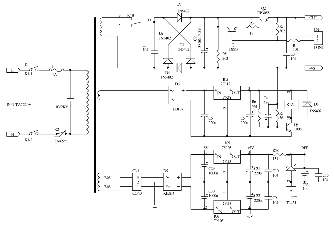
Here's an example of a 18v 2A power supply, using two transformer taps, a separate winding for the relay which enables the second tap or not, and two separate small windings for +/-8v and +/- 5v for the multimeter chips :

transformer, power transistor, linear regulators for opamps , relays, multimeter chips


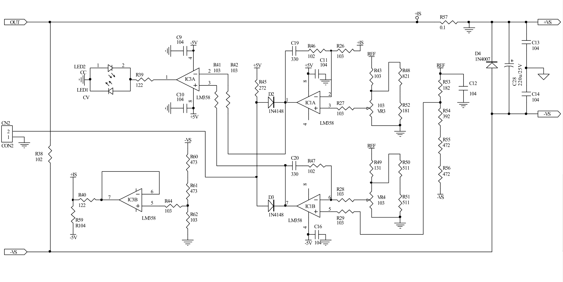
opamp to adjust voltage and current,  current limit leds , output ... all jellybean components on this one and the previous part


multimeter chips (one for voltage, one for current) ... icl7106 is with lcd segments , icl7107 is with normal led segment (so you could use 7 segment digits)..


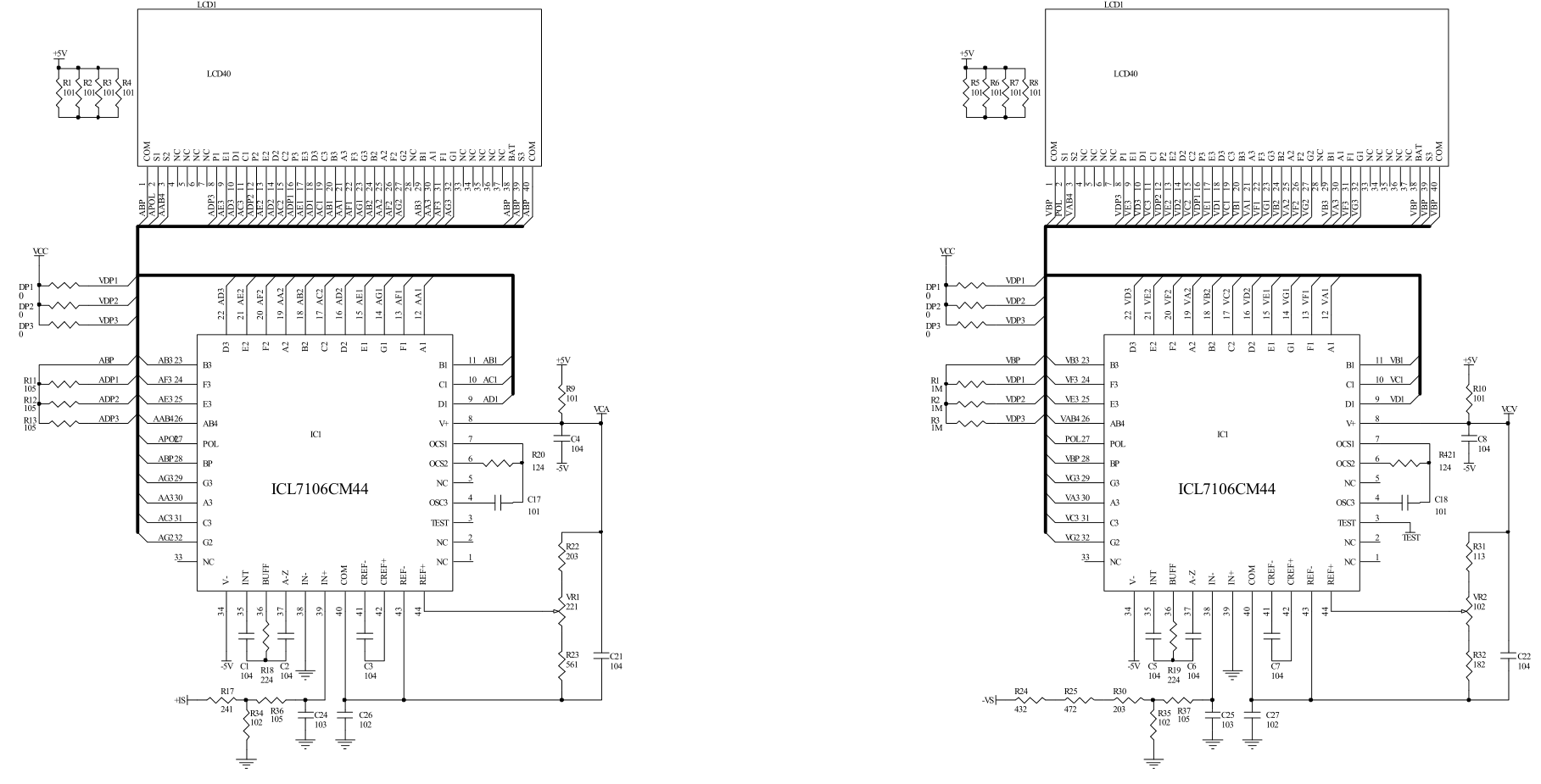
this last part is the only slightly more difficult part to make (and the chips are more expensive) but you don't really need it, you can get less accurate ready made meters from ebay. if you do make them, you need some film capacitors and more accurate resistors and you must read the chip datasheet to understand how it works etc..
 

Offline stev.dkTopic starter

  • Regular Contributor
  • *
  • Posts: 67
  • Country: dk
Re: Building a bench power supply
« Reply #2 on: May 19, 2013, 09:25:46 pm »
Thanks for the reply. When i got the transformer i wanted to use it for a small guitar amplifier. I see the point about the transformer not working for this purpose. I think i'll put it back in the box, and wait for another project suitable for it (small guitar amp?).

Is it possible to use multiple 220V -> 12V transformers, if a single transformer with the taps required is not available?

The LM7805 should be able to do 35V up to 1.5A (according to the datasheet).

I know about the diodes, i was just using whatever i had laying around  :)

So if im not going to use this transformer, and these volt/ammeters are so cheap (found them on ebay at the price of a worn out t-shirt - i KNOW they're not accurate, but i only need a guideline. For accuracy i'll be using my fluke 87) i might consider doing a switch mode variable PSU.
Crank it up till' everybody's ears are bleeding, then back off just a notch.
 

Offline mariush

  • Super Contributor
  • ***
  • Posts: 5250
  • Country: ro
  • .
Re: Building a bench power supply
« Reply #3 on: May 19, 2013, 09:47:23 pm »
Yeah, guitar amp is a good ideea.  I suggest one with a tda2030, it's fairly easy to do : http://www.st.com/web/en/resource/technical/document/datasheet/CD00000128.pdf  (see page 8, figures 17 and 19) .. just make sure you give it maximum 36v (use some diodes in the bridge rectifier with large voltage drop)

Yes, you can use multiple 12v transformers.

Technically you can use 35v input on a 7805, but the total power dissipation is internally limited and can not exceed a certain value. Linear regulators like 7805 dissipate the voltage difference as heat, and they have a maximum limit, and even so, you'd need ridiculously expensive heatsinks to remove the heat if you want both high current and high input voltage.
So you can have 35v in, 5v out but at something like 10-50mA, if you demand 1-2A you're out of luck.

For example see : http://www.fairchildsemi.com/ds/LM/LM7805.pdf

Thermal Resistance Junction-Cases (TO-220) 5 °C/W
Thermal Resistance Junction-Air (TO-220) 65 °C/W
Operating Temperature Range LM78xx -40 to +125

Then on next page it says V out = 5v at Po = 15w .. that's a hint that the regulator may internally limit itself to 15w power dissipation if I understand correctly. So at 35v input - 5v output you have 30 watts so the maximum current it could output and stay within 15w power dissipation would be something 15w / 30v = 0.5 A
So if the maximum power dissipated is 15w and you feed it with 35v, you're limited to 0.5A of current.
BUT, even so, let's do the math on what heatsink you'd need for that...

assume room temperature is 25c ... the chip operates up to 125c as it says in datasheet so we have 100c to work with.
100c / 15w dissipated =  6.6 degrees c  / watt

The 6.6 c/w is lower than the resistance junction to case air, so we definitely need a heatsink.

value needed = value calculated - resistance junction-case - resistance of material between heatsink and case (usually about 0.1 for thermal paste, 0.3-0.5 for silicon pads or something like that)

so heatsink needed = 6.6c - 5c - 0.1 = 1.5c/w

You're looking at about 10$ worth of heatsink :

http://uk.farnell.com/fischer-elektronik/sk-571-10-sa/led-heatsink-standard-extruded/dp/1850077
http://uk.farnell.com/fischer-elektronik/sk-04-100-sa/heat-sink-100mm/dp/4621529

With a fan, you can probably manage something cheaper, let's say 4c/w heatsinks, but then what's the point, you still have only 5v @ 0.5A, you're better off getting a better transformer in the first place.

« Last Edit: May 19, 2013, 10:48:07 pm by mariush »
 

Offline stev.dkTopic starter

  • Regular Contributor
  • *
  • Posts: 67
  • Country: dk
Re: Building a bench power supply
« Reply #4 on: May 19, 2013, 10:18:15 pm »
I appreciate the math and information given about the heat dissipation, cause i know next to nothing about that. I do however have a box filled with different kinds of heatsinks from old computer motherboards and powersupplys ect. I can never get enough heatsinks ;)

I dont know if i'll be needing more than 500mA on the 5V rail, and i know i have a heatsink suitable for the job. But i think i'll save my ring type trasformer for another project and get one with multiple taps, cause i have never worked with those (in diy projects from scratch at least not). And the main reason for building stuff like this is to learn.
Crank it up till' everybody's ears are bleeding, then back off just a notch.
 

Offline stev.dkTopic starter

  • Regular Contributor
  • *
  • Posts: 67
  • Country: dk
Re: Building a bench power supply
« Reply #5 on: May 20, 2013, 12:42:56 am »
I found some components im thinking about building my power supply with. I found a transformer (ring type like the one i have) but with 2x15VAC secondary. Im thinking about using LM150, 1,2-30V 3A regulator. Since im aiming at 3,3-24V at 2A, it should suit my needs. I have drawn a circuit with my idea on how this could (might/might not) work.

The idea is to use a relay as shown in the schematic to switch between using one and two of the secondary outputs. The relay sensor is placed in a voltage detection circuit, thats connected to the output of the LM150. The idea is, when the output voltage exceeds 10V or 12V, the transistor is turned off, and the relay will switch and use both secondaries.

I haven't crunched any values as to what transistor, relay, zener diode ect. to use in this circuit. I do however (of course?) want to draw as little current as possible in the detection circuit.


Looks reasonable? Im thinking if i want fine and coarse adjustments, or a 10-turn pot... i think theres pro's and cons with both... might not even matter anyway....

Now i'll go sleep on it :=\
« Last Edit: May 20, 2013, 12:47:47 am by stev.dk »
Crank it up till' everybody's ears are bleeding, then back off just a notch.
 

Offline mariush

  • Super Contributor
  • ***
  • Posts: 5250
  • Country: ro
  • .
Re: Building a bench power supply
« Reply #6 on: May 20, 2013, 01:20:52 am »
"ring" ... they're called toroidal transformers.

15v AC is still a bit much.  Don't forget transformer ratings are usually RMS.
The DC voltage will be 15x1.414 = 21v after bridge rectifier you have ~ 20v. So, with both windings you'll have 40v and the maximum rating this LM150 can do is 35v.

I think you could use a voltage divider, an inverter/buffer with schmitt trigger, (maybe something like 74HC14N) and a npn/pnp transistor to power the relay.. schmitt trigger is cool because they output either low or high but  there's a voltage range where the output doesn't change, for example the outputs correspond to something like < 2v and >3v  so once it goes over 3v it goes into one state and then has to go as low as 2v to switch back to the other state.
So you could set the voltage divider in such a way that it enables relay at something like 90% of first tap but disables it only at 70-80% of first tap.

I don't know about the way you enable the relay in that schematic, I'm too tired to follow it now.

There are 5v, 12v, 24v relays ... you can connect two wires on a winding, use a diode to do half wave rectification, a capacitor to smooth out the dc and you have 12v dc .. a cheap 7805 or 7812 100mA (those tiny round ones without heatsink) regulator will be enough, such 12v relays only need about 30-40mA. It's better to drive it directly from transformer, not after the regulator, the relay won't work reliably with a wide range of voltages.
 

Offline stev.dkTopic starter

  • Regular Contributor
  • *
  • Posts: 67
  • Country: dk
Re: Building a bench power supply
« Reply #7 on: May 20, 2013, 01:45:19 am »
Didn't know the english word for it. In denmark it's called a ring-core transformer :-)

I'm getting pretty tired to, hence i forgot about the x1.414, BUT it dosn't matter cause the transformer i found is available in a wide range, so i can get a 2x9VAC , but that might leave me a bit low for 24V output. Might want to go with 2x12V... but im to tired to crunch any numbers right now.

I'll go check out the schmitt trigger.

Okay i made a mistake on the schematics... R5 should NOT be connected to the regulated output. R5 should be connected between the collector of T1, and the Vin (could be 12VDC from the transformer).

The idea in the detection circuit is, when the regulated output is less than, lets say 10V, the zener diode blocks current from saturating the base of T1, and the relay is off. When the regulated output exceeds that, the zener diode lets enough current through to saturate the T1 base, turning on the relay. Again, when the voltage drops the zener diodes blocks current to T1 base, and the relays turning off.
Crank it up till' everybody's ears are bleeding, then back off just a notch.
 

Offline stev.dkTopic starter

  • Regular Contributor
  • *
  • Posts: 67
  • Country: dk
Re: Building a bench power supply
« Reply #8 on: May 20, 2013, 02:55:40 pm »
I did some work on the schematic. Fixed my mistake, and trying to clear it up a bit.

I like the schmitt trigger circuit, but i dont want to get a quad package op-amp using only one, if i can make it with other components. I havn't been working with zener diodes yet, so this is based on other diagrams and readings. I have no practical experience, so i might have got this completely wrong.


Tonight im planning to do some further study on voltage level detection, getting a 12v supply of the transformer for the relay and volt/ammeter. Then i think im going to split the schematic into sections: power supply, voltage regulation and a voltage detection section.
Crank it up till' everybody's ears are bleeding, then back off just a notch.
 

Offline Paul Price

  • Super Contributor
  • ***
  • Posts: 1443
Re: Building a bench power supply
« Reply #9 on: May 20, 2013, 03:37:37 pm »
The switching power supply shown in the attached .jpg is very efficient(About 2 watts  of heat at full load or overload), so the single chip needs only a small heat sink and you can salvage a nice large toroidial (ring) inductor and a heat sink and diodes and output filter capacitors  from a discarded desktop PC power supply to get the most and the hardest to find parts needed, so it practically free. Don't need to use the 2576HV shown, just use a much cheaper LM2576-ADJ.  This circuit already has short circuit protection but you can add adjustable current limiting/constant current mode with just a single transistor, a sense resistor, a current adj. front panel potentiometer and a LM393 comparator.

The power supply drawing shows 55V in, but your Ring transformer will only supply around 32V max in and so your output will be likely limited to about 25V at the full 3-amps output but can output up to 29V at lower currents.  Det virke fint.

The relay idea is ikke godt, there are very high surge currents when switching into the filter capacitors and it will fry your relay contacts lige snarts.
« Last Edit: May 20, 2013, 04:07:39 pm by Paul Price »
 

Offline stev.dkTopic starter

  • Regular Contributor
  • *
  • Posts: 67
  • Country: dk
Re: Building a bench power supply
« Reply #10 on: May 20, 2013, 04:16:30 pm »
Thanks for your reply Paul!

I'll take that into concideration. It looks soo perfectly simple, the way i like it. I like your Danish comments in there, it made me laugh :-DD
Crank it up till' everybody's ears are bleeding, then back off just a notch.
 

Offline stev.dkTopic starter

  • Regular Contributor
  • *
  • Posts: 67
  • Country: dk
Re: Building a bench power supply
« Reply #11 on: May 21, 2013, 01:02:02 am »
Im starting my work based on my transformer, and the LM2576-ADJ chip, cause the only thing i need for this, is the LM2576-ADJ. I made a schematic for the power supply section. Pretty basic actually, but i've added some input protection stolen from a scrap part i have lying around. It's a ceramic fuse, so i believe it to be a hrc fuse? I cant see the value of the varistor, cause it has heat shrink on it, but it's from a 2.5A circuit, so it should fit my needs. I can't see the value of the cap, cause the varistor is in the way, and i've shipped out my old soldering station, waiting for my hakko FX-888 to arrive :-+ From the same circuit im able to score a 1K thermistor. The bridge rectifier is a KBL406, which should handle 600V 4A.

Im pretty happy, with what i've got this far, even though it's pretty basic. I left out a supply for volt and ammeters in the first place. When i get the chip and assemble the thing, im going to measure out reference voltages 5, 7.5, 9, 12, 15, 18 and 24 with my fluke 87 (when it arrives  :-+) and mark it with a dymo or something like that.

Please comment.
Crank it up till' everybody's ears are bleeding, then back off just a notch.
 

Offline mariush

  • Super Contributor
  • ***
  • Posts: 5250
  • Country: ro
  • .
Re: Building a bench power supply
« Reply #12 on: May 21, 2013, 01:11:02 am »
Just read the LM2576 datasheet and pay attention to what it says.

The IC will be very unstable on a breadboard, and is quite possible to not work right on prototyping board/stripboard too... you need to have some components physically as close as possible to the IC leads and you also need as thick ground traces as possible.

That's the problem with switchers, lots of noise and issues with inductor selection (which has to handle the peak current and other specs that are mentioned in the datasheet) and placing the parts on pcb.
Either way, i think it would come out "optimized" for a particular voltage and when you adjust the voltage, the ripple will increase and the ic will be inefficient. A pi filter at the output and possibly even a ferrite bead would help smooth the output.
 

Offline Paul Price

  • Super Contributor
  • ***
  • Posts: 1443
Re: Building a bench power supply
« Reply #13 on: May 21, 2013, 01:16:40 am »
Looks like a great start! 
I don't know what you are going to do with the 1K temperature sensitive device.
If you need to how add complete MCU control and metering and constant current to this supply I know how to do this.
 

Offline stev.dkTopic starter

  • Regular Contributor
  • *
  • Posts: 67
  • Country: dk
Re: Building a bench power supply
« Reply #14 on: May 21, 2013, 02:06:52 am »
I am capable of making my own PCBs, so im not tied to using a vera or stripboard. I'll actually enjoy getting into designing a PCB, etching it og drill holes with my (new) drillpress (didn't have one last i did PCB's and i broke a lot of drills |O)

If you look at the schematic Paul uploaded, theres a optional filter, at the very end, looking a bit like a pi filter? I have lots of ferrite beads, so i might have one suitable for this job aswell :-)

Paul can you specify what MCU control is?
Crank it up till' everybody's ears are bleeding, then back off just a notch.
 

Offline c4757p

  • Super Contributor
  • ***
  • Posts: 7799
  • Country: us
  • adieu
Re: Building a bench power supply
« Reply #15 on: May 21, 2013, 02:11:12 am »
"MCU" is microcontroller (unit). It's just digital control.
No longer active here - try the IRC channel if you just can't be without me :)
 

Offline Paul Price

  • Super Contributor
  • ***
  • Posts: 1443
Re: Building a bench power supply
« Reply #16 on: May 21, 2013, 02:32:25 am »
MCU
(1) (MicroController Unit) A computer on a single chip. A device that often has integrated peripherals for many needed and useful functions, such as A2D, communication,  as well as programmed fixed and volatile memory RAM and always  the capacity to do general purpose computing according to a stored program.  As such, it can monitor, communicate and control other devices  through it many ports offering input and output to/from the core processor. It can also emulate many complex tasks usually performed by discrete circuitry or even replace or provide the functionality of other complex function integrated circuits. Among a myriad of useful things, it can control display devices and interface with the user through controls such as potentiometers and switches, all the while emulating the control usually offered by a discrete physical hardware approach to, even to enhance some non-digital analog applications such as in a power supply controller circuitry.

In other words it can be a power supply management, display and controller chip, all by itself, controlling a few external power active components with an advantaged minimum of added integrated interface circuitry.
 

Offline stev.dkTopic starter

  • Regular Contributor
  • *
  • Posts: 67
  • Country: dk
Re: Building a bench power supply
« Reply #17 on: May 21, 2013, 02:49:22 am »
Arhh okay, i was confused (haven't sleept for to long i think), cause i did a google search on MCU control, and got some stuff about Multipoint Control Unit's, and i didn't see the potential for that here, lol.

I have an atmel atmega32, that i used for another project that died. I still have the firmware for the LCD display though. Im a tiger at programming these things, cause i am originally a programmer.

Your saying i could hook up a pot to the adc, following the position of the pot, and displaying it on the display, and somehow control the LM2576 with the microcontroller? Or, actually im pretty sure, thats possible (maybe not with that exact ic and micro controller), but im not sure how. My guess is using the dac and/or some pwm?
Crank it up till' everybody's ears are bleeding, then back off just a notch.
 

Offline Paul Price

  • Super Contributor
  • ***
  • Posts: 1443
Re: Building a bench power supply
« Reply #18 on: May 21, 2013, 10:53:24 am »
Yes, using the A2D to monitor voltage and current and even control the switching transistor of a PWM power supply and all this according to user set values (voltage, max current from pots)  fed into A2D inputs, while outputs drive 7-seg displays, etc.
 

Offline MARSHALBSB

  • Contributor
  • Posts: 17
Re: Building a bench power supply
« Reply #19 on: June 13, 2020, 06:04:52 pm »
Funny thing! I'm trying to fix a DC Power Supply that's exactly like that one. Including the relé comment  :-DD


Share me

Digg  Facebook  SlashDot  Delicious  Technorati  Twitter  Google  Yahoo
Smf