Author Topic: Custom EE Workbench - project log  (Read 3872 times)

0 Members and 1 Guest are viewing this topic.

Offline zittTopic starter

  • Regular Contributor
  • *
  • Posts: 113
  • Country: us
    • Pinball-Mods.com
Custom EE Workbench - project log
« on: May 14, 2018, 04:58:26 am »
For years I've been doing my Electrical Engineering prototyping using a woodworking bench I bought about 15 years ago while in Oregon. Simply put; the bench has done its job; but has been becoming increasingly cramped; as I get more and more equipment. This thread intends to document some of my work for peer feedback and improvement suggestions.

I've been on a test equipment buying spree the last few months; Scoring a new-to-me Agilent DSO6104 direct from Keysight in Malay. I've also sourced a Used/parts only Mantis Elite stereo microscope in the last week; as my age / eyesight is just plain tired of fighting the SMT PCBs.  The result is I've simply outgrew my old bench which as a depth of less than 16inches.


I found a local surplus company whom sells office furniture; and secured a 24x60" standing desk which I wanted to use as my new electric bench. After getting the standing desk home; I realized that the 24inch depth while better than my existing bench wasn't a massive improvement. I also measured the spot in my "Mod" room and 60inch was probably almost too long when combined with the laser cutter table. I was going to hack the back of the existing top by "gluing" a extension on the back of the bench. I then realized there may be a balance issue by just gluing onto the back of existing slab.

I also wanted to elevate my soldering equipment to get it off the desktop so I could work on the bigger 90s Pinball boards without issue. So I hatched a plan to hand build a custom desk using the standing desk's frame. I remembered I had about 1/2 a sheet of two sided Melamine surfaced MDF left over from my Star Trek Captain's Chair restoration; so this was a great opportunity to rid myself of space hog behind my pinball machines.
« Last Edit: May 21, 2018, 04:29:08 am by zitt »
 

Offline zittTopic starter

  • Regular Contributor
  • *
  • Posts: 113
  • Country: us
    • Pinball-Mods.com
Agilent MSO/DSO 6000 series VESA mount
« Reply #1 on: May 14, 2018, 05:52:58 am »
Before we get to the desktop; one of the goals of this project was to VESA mount the DS06104 so it can "hover" over my workbench instead of taking up space on the bench. This idea isn't mine; I came across a video of the idea recently:
https://youtu.be/IbPh7-DGkC8?t=52

Agilent doesn't provide a VESA mount on this scope; so I was going to have to get creative.
First; I looked at cheap monitor arm options. Amazon has an inexpensive "basics" Monitor Arm which met the weight requirements of the scope. I picked up a amazon warehouse deal with a cosmetic issue because it was less than 75USD.

Prior to purchase I downloaded the basic's assembly manual to ensure it'd fit my needs. The critical issue; is that the scope doesn't have a vesa mount at all; much less "realestate" to mount on the back. I hatched a plan to create a custom bracket which would "mount" with little-to-no modification of the scope itself - since it's an expensive puppy even by today's standards. Since I was mounting on the bottom; I needed the monitor arm to allow a tilt of 90 degrees. The Amazon arm only allows for 70 degrees max (see page 4 ) which may be acceptable; but wouldn't be sure until I had the bracket ready.

Using my scope as a template; I created a VESA bracket in QCad. Here's my Rev0:


The idea is that I'd remove the rubber feet and use the feet slots to secure the bracket to the bottom of the scope. The first slot pre-attached to the bracket to keep the bracket rigid. The foot (on the right); would be screwed to the bracket after it's in place. 
The VESA 75mm and 100mm hole patterns are centered at the "empirically" determined center of gravity of the scope.

Additionally; I purchased an factory sealed MSO option for the scope from Ebay so I wanted to still be able to route the Digital signals under the scope as Agilent intended. This means I wanted to have the plastic "chute" mounted to the bottom of this bracket; hence the added features. And last but not least; I needed to keep the venting intact on the scope except for some extra material needed for the bottom right 100mm VESA hole.

I used to be a member of Techshop before they went bankrupt last Nov. Had they not mismanage the company; I would have used the Austin/Round Rock TS to waterjet myself a bracket. But alas; that ship has sailed. I knew I was going to have to outsource the waterjet work; so I wanted to "measure twice, cut once" - so I laser cut the bracket out of 1/8" scrap acrylic I had here in the mod room and did a test fit. The test fit showed that I had mis-measured a couple of places and bracket wouldn't actually fit between the rear feet. I put the bracket back on the laser table and trimmed some edges so it'd fit.

With the revisions tested and functional I was ready to outsource. Ideally; I'd have the bracket water jetted out of Stainless steel - however, I had concerns about the weight, cost, and more importantly rework ability if the bracket wouldn't fit the Amazon Arm. I asked a former Techshop instructor if he'd be willing to take the job (paid) of water jetting my newly designed bracket. He agree and had it cut right away.

With the bracket in hand I ordered the Amazon Arm. When I had both; I set about figure out how to mount the scope to the bracket, and the bracket to the Arm. I already knew I needed to keep the MSO digital chute under the bracket; so I went with some aluminum M4 standoffs between the bracket and vesa arm mount. I measured the chute and picked the next largest standoff size; 5mm.

I then realized since I was using standoffs anyway... I might as well try and compensate for the additional 20 degrees I need from 70 to 90 so the scope could be "horizontal" to my desk. Trig has never been something I could easily do/understand; but using some right angle triangle math; I was able to figure out some how to make up most of that 20 degrees using off-the-shelf standoffs.  If I combined the 5mm standoff with a 25mm standoff, I should be able to make up about 14 degrees. With the new plan; I ordered standoffs from Mouser and M4 hardware from McMaster-Carr and impatiently waited for them to arrive.
 

Offline zittTopic starter

  • Regular Contributor
  • *
  • Posts: 113
  • Country: us
    • Pinball-Mods.com
Re: Custom EE Workbench - project log
« Reply #2 on: May 14, 2018, 06:13:26 am »
While I waited on VESA hardware; I started some hand drawn sketches and started figuring out what I wanted to do with the desktop. I wanted a 30inch depth; a shelf; and a power strip "shelf". Since this was MDF; I knew screws would easily strip out any holes so the powerstrip shelf was made from 2x2" pine as was the shelf legs. I had originally intended to use the shelf to bolt on the Amazon Arm; so I wanted the MDF to have some strength backup so I added 4 qty 2x2" as the legs in the corners.

During assembly; I tried my hand at using a hand router to "embed" the shelf in the 3/4" MDF - again for strength. If there is interest; I'll try to grab some detail pictures.

Other construction notes:
  • Wood glue can't "penetrate" melamine (a plastic) because it isn't porus. I used the hand router to "trim" away the white melamine when I need to make a strong (clamped) glue line.
  • Again; because I could - I rounded the front corners of the desk to try and prevent hitting the corners in the dark.
  • Also; because routers are awesome - I used a 1/2" rounded bevel cutter to round the front edge of the desk.
  • OCD kicked in; so I primed and painted the pine legs and any exposed MDF which wasn't an edge.
  • Amazon Prime rocks... so I had them send me some 7/8 inch white iron-on edging, some screw covering caps, and some white seamfil.
Over a weekend, and several after-work nights - I pieced together the new desktop:
« Last Edit: May 14, 2018, 06:51:17 am by zitt »
 

Offline zittTopic starter

  • Regular Contributor
  • *
  • Posts: 113
  • Country: us
    • Pinball-Mods.com
Re: Custom EE Workbench - project log
« Reply #3 on: May 14, 2018, 06:39:23 am »
I was about done; when I considered trying my hand at making drawers. I'm no expert; this was my first time... but using some Youtube videos and my own plans; I modelled the desktop; stand; and engineered a two drawer system for under the desktop.


Armed with this drawing and a bom list (created from drawing); I knew about how much lumber I needed and the sizes which would fit. I went to Lowes and bought the materials on Friday after work. Saturday; I built the drawer shelves out of 5.5" Primed MDF. Sunday, after the wood glue had dried - I assembled the full drawers:


After an early dinner on Sunday; I removed the old standing desk top; and bolted my new desktop to the legs.


I attached the Amazon Arm to the side wing I added and attached the scope to the arm:


A Closeup Shot:


I'll try to grab some better (lit) pictures later when it's installed in my Mod room.

Still to do:
  • SeamFil-ling corners and scratches
  • Hide drawer fronts with a Facade... with some custom drawer pulls fitting for the project
  • ESD matting
  • Move into final position.
  • possible above desk shelving and/or lighting.

Stay tuned...
 

Offline RobertHolcombe

  • Frequent Contributor
  • **
  • Posts: 275
  • Country: au
Re: Custom EE Workbench - project log
« Reply #4 on: May 14, 2018, 07:30:21 am »
Love the articulating arm idea, totally going to implement that myself one day

At the moment I just have a scope on my bench on a floating shelf but it still gets in the way sometimes

Have to give the thread a proper read after work  :-+
 

Offline xani

  • Frequent Contributor
  • **
  • Posts: 400
Re: Custom EE Workbench - project log
« Reply #5 on: May 14, 2018, 11:36:34 am »
You might look into getting one of those lamps on arm  ( example, altho I have some noname one ),  I have 2 of those (one on each side of the desk, to reduce shadows) and they are pretty handy as you can just move them where you need it.
 

Offline zittTopic starter

  • Regular Contributor
  • *
  • Posts: 113
  • Country: us
    • Pinball-Mods.com
Re: Custom EE Workbench - project log
« Reply #6 on: May 14, 2018, 09:45:52 pm »
You might look into getting one of those lamps on arm

I had one of these on my current workbench. I was made in the 70s and has been used as a workbench light since I was in JR high. I recently retired it because it was falling apart. I replaced it with one of these:

so that I can read the part numbers on SMT components now. Prior to this; I'd been using my "over 40 app" on my phone to read the topside marks.

I may look at repair my old desklamp when I get a free moment. It's seen better days; but it's also been in the family for most of my life. :D
« Last Edit: May 15, 2018, 07:25:51 am by zitt »
 

Offline zittTopic starter

  • Regular Contributor
  • *
  • Posts: 113
  • Country: us
    • Pinball-Mods.com
Re: Custom EE Workbench - project log
« Reply #7 on: May 15, 2018, 07:15:44 am »
Spent about an hour or two after work putting latex caulk in cracks of the desk - mainly at the rear shelf wall. Besides having an unfinished look which bothered me... there was a real risk that component leads, small bits of solder, and/or wire could get wedged in the rear cracks. I figured the caulk would help keep those on the table so they could be cleaned up.

Additionally; I designed a couple of EE specific drawer pulls which should look good on the drawers:

I was actually pretty surprised no one had published drawer handles like this.
The pulls are tapped with a #10-32 thread.

I ordered a set in Polished White as a fit check. If they work out; I'll re-order in the more expensive Polished nickel Steel.
« Last Edit: May 15, 2018, 07:24:51 am by zitt »
 

Offline zittTopic starter

  • Regular Contributor
  • *
  • Posts: 113
  • Country: us
    • Pinball-Mods.com
Agilent MSO/DSO 6000 series VESA mount - Part 2
« Reply #8 on: May 21, 2018, 04:40:55 am »
Here are some detail shots as I install the MSO option onto the VESA mount.

The digital channel chute installed onto the aluminum VESA bracket:

You can also see the 25mm standoffs installed here.

The 25mm standoffs are held in place with countersunk M4(x0.7mm thread)x10mm long screws. The M4x5mm standoff is threaded onto the 10mm screw and the 25mm standoff is threaded on the remaining 5mm of the 10mm screw.


Then using Amazon's supplied M4 thumbscrews; we thread the back 100mm VESA holes directly to the aluminum bracket with a 5mm standoff as pictured:


The Front thumbscrews thread into the 25mm standoffs:
 

Offline zittTopic starter

  • Regular Contributor
  • *
  • Posts: 113
  • Country: us
    • Pinball-Mods.com
Re: Custom EE Workbench - project log
« Reply #9 on: May 21, 2018, 05:09:39 am »
Yesterday was move-in day for the bench. Today I finally got it setup to the point where I can take some pictures.

I started by mounting some rubbermaid fasttrack shelving above the desk to store some my old Tek 465B and some other odds and ends. I mounted the fast track to three studs for so it could support some weight and lowered my misc drawer by a few inches due to the new shelving.


My soldering equipment resides on the top shelf with the 4ft power strip mounted on the 2x2 mounted behind the shelf. The OCWhite magnifying LED lamp serves dual purpose as task lighting and is also mounted to the upper shelf.

I re-used my ESD matting from the old desk; cleaned it up a bit and did a proper ESD connection to earth ground. I also included a ESD strap port which is mounted under the upper shelf. I still need to source a comfortable ESD strap... so if someone has any suggestions; I'm open to them.

I repaired a "for parts" Mantis Elite stereo scope (found on ebay) and attached it to the desktop. I had to use some JB Weld. some #4-40 and to repair the hinge and front viewing cover but it seems to be rock solid right now. The scope is outfitted with a 10x objective and a new 4x objective is on the way. The Seller sent a 5V DC wall wart with the base; but it wasn't correct as the LED lighting in the scope requires 9VDC ~1.5amps according the the base... so I had to order up a 9VDC 2A supply from Amazon.


Finally; I attached my Amazon Basics Arm with MSO6104 attached. I still need to figure out a way to store/protect the DIO probes when not in use.


Have some pretty cool ideas for the drawer faces along with the drawer pulls. I got a shipping notice from shapeways in the test White plastic. If they work out; I'll post some pictures and order the pulls in nickel stainless steel.
« Last Edit: May 21, 2018, 05:21:27 am by zitt »
 

Offline GreyWoolfe

  • Supporter
  • ****
  • Posts: 3651
  • Country: us
  • NW0LF
Re: Custom EE Workbench - project log
« Reply #10 on: May 21, 2018, 01:02:03 pm »
For all my probe/test lead storage, I use Chinese take away plastic containers.  The ones we get have clear lids and are fairly flat and wide.  They stack nicely.  I use a label maker to mark what the scope probes are.
"Heaven has been described as the place that once you get there all the dogs you ever loved run up to greet you."
 

Offline ANTALIFE

  • Frequent Contributor
  • **
  • Posts: 509
  • Country: au
  • ( ͡° ͜ʖ ͡°)
    • Muh Blog
Re: Custom EE Workbench - project log
« Reply #11 on: May 21, 2018, 01:18:32 pm »
Love the scope mount, might use that idea later on when I finally get a digital scope

Offline zittTopic starter

  • Regular Contributor
  • *
  • Posts: 113
  • Country: us
    • Pinball-Mods.com
Re: Custom EE Workbench - project log
« Reply #12 on: May 22, 2018, 04:31:22 am »
For all my probe/test lead storage, I use Chinese take away plastic containers.  The ones we get have clear lids and are fairly flat and wide.  They stack nicely.  I use a label maker to mark what the scope probes are.

I assume you mean while the probes aren't in use/attached to the machine.
My issue is that because the Digital channels reside in the chute which is under the VESA Arm bracket; I need to have a way to store the probes attached to the machine. Your plastic container idea isn't ideal... but is probably the best solution given they need to remain attached to the machine.
 

Offline GreyWoolfe

  • Supporter
  • ****
  • Posts: 3651
  • Country: us
  • NW0LF
Re: Custom EE Workbench - project log
« Reply #13 on: May 22, 2018, 01:13:02 pm »
You are correct.  I don't leave them attached.  I have dust caps on all BNC connectors on all the equipment.
"Heaven has been described as the place that once you get there all the dogs you ever loved run up to greet you."
 

Offline zittTopic starter

  • Regular Contributor
  • *
  • Posts: 113
  • Country: us
    • Pinball-Mods.com
Custom UdooX86 PC for EE Workbench
« Reply #14 on: June 09, 2018, 07:24:15 am »
Now my attention turns to a miniature PC for the Workbench. A while back I kickstarted a X86 miniPC board by Udoo. I had kickstarted it as an Advanced with 4GB of DDR and a 32GB emmc. At the time I outfitted it with an 80mm Transcend 256GB SSD using a 3D printed bracket I created. I also outfitted the PC with a Intel Dual Band AC 8260 WIFI NGFF card and a set of Wifi Antenna’s to connect to the AC 8260 card. At the time I didn't have any real uses for the board; but knew it would come in handy... Since Intel discontinued the Arduino 101 on the board; I didn't see much point In trying to use it for a maker project. :(
The purpose of this PC is mainly to look up Datasheets, view Schematics/PCB files, and to run a Windows XP 32 Virtual machine to run my laser cutter's 32bit drivers.

I decided I wanted to create a small acrylic case for the PC and mount it under the new desktop. I did a search on Udoo's forums and found a opensource case by WalkingRobot. I imported his files; but knew I'd have to modify them for several reasons.
  • I had an 80mm SSD instead of the stock 60mm
  • I didn't want the complete cut outs for the Arduino 101.
  • I wanted to add some WIFI Antenna mounts.

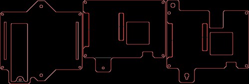
I pulled out QCAD and re-engineered the case for my needs. This was my final CorelDraw file I sent to my Laser cutter:

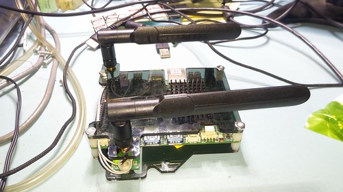
I actually went thru an intermediate step when I printed the center top... but quickly realized that I need the wifi antennas during final testing.

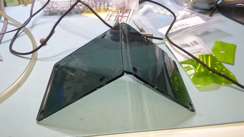
I laser cut the acrylic case out of some scrap 1/8" smoke acrylic I had laying around from my computer mod days. Here;s the finished case mounted together with some #6-32 standoffs, some nuts, and scome screws:


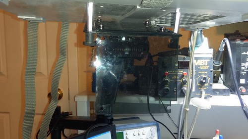
I mounted it to the side of the drawer so it'd be out of the way from my knees and what not.

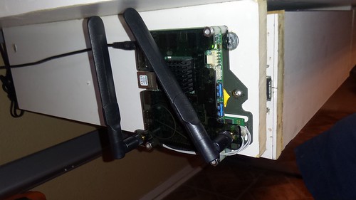
The PC is mounted to drawer with some #6 woodscrews.

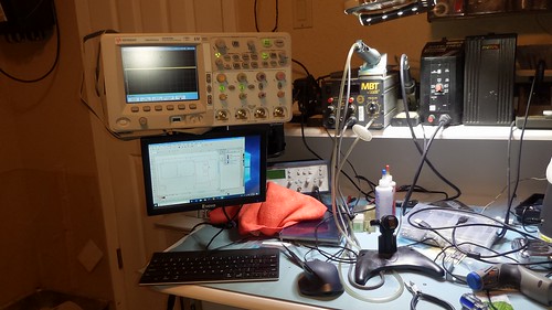
Next; I turned my attention to how I was going to work with the PC. I need a monitor, hdmi preferably. Turns out I had a monitor arm right there... so use it. I had picked up a small "10 inch test monitor" off of Amazon in Feb of last year. It's intention was to be small so I could debug computers on the work bench... but honestly; the monitor has several killer issues which makes it difficult to use. 1) it's bezel is too big; so things like the windows start button get cut off. 2) it doesn't like the early boot mode of the udooX86. It's really can't be used in bios settings; only when the system is booting and when the resolution has been "shrunk" to fit within the bezel. But it was cheap-ish... so might as well use it. If I were buying a new monitor for this rig; I'd probably go with something like this:
11.6 1920x1080 display with 10point touch.

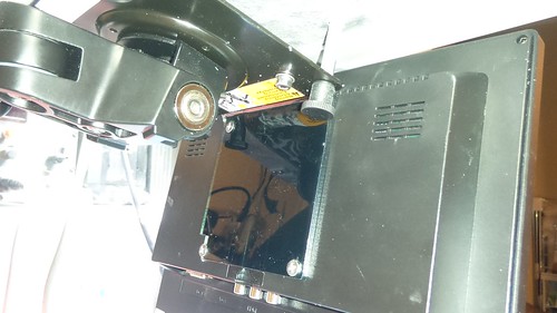
I wanted to mount to my scope's new monitor arm; so I created a right angle 75mm bracket in QCAD and laser cut it:


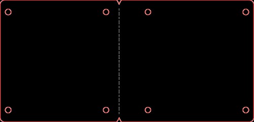
Using a heat gun and some clamps; I bent the bracket at the dotted line:


and mounted it with the leftover amazon hardware and some spare 4mm nuts I had on hand:


I then mounted the monitor to the bracket using some additional 4mm hardware:


I didn't want wires on my desk; so I ordered an hdmi cable and fed it thru monitor arm. I had an older Logitech Bluetooth keyboard and a Logitech BT mouse that I acquired over the years. Both paired perfectly with the Intel AC8260 card's Bluetooth radio:


Finally; I paired the PC w/ a bluetooth speaker so I can stream some music while working on projects.

The PC runs pretty good for only 4GB of DDR. I do want to upgrade the monitor to the one I pointed to above... but I've been spending way too much cash on this project to date.

Incidentally; I did get my Resistor and Inductor pulls in from shapeways a few weeks ago. I also risk-ordered the pulls in nickel, polished, stainless steel because Shapeways was doing a small percentage off sale. Here's the pulls printed in White Processed Versatile Plastic:

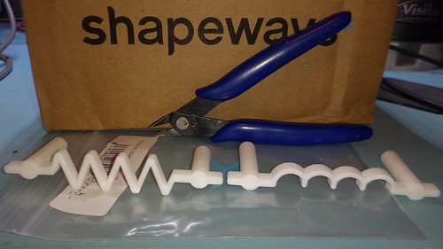
They look good; but for some reason the tapped holes were not #10-32 as I had thought I designed... but closer to #6-32. As a result; I'm about 95% sure the metal pulls will show up with the smaller holes.

The metal pulls shipped a few days ago... so hope to have them in the coming days. I've already started working on my drawer faces... I'll post more pictures when I get them finished.
« Last Edit: June 09, 2018, 07:45:40 am by zitt »
 

Offline zittTopic starter

  • Regular Contributor
  • *
  • Posts: 113
  • Country: us
    • Pinball-Mods.com
Re: Custom EE Workbench - project log
« Reply #15 on: July 24, 2018, 06:00:08 am »
Time to wrap up this project log by putting the final touches on the drawers.

As I stated; I designed some custom drawer pulls and had them 3D printed at Shapeways out of Stainless Steel; so I wanted to make a nice drawer face to match the theme of the ee bench. To do this I layed out a simple trace pattern in EagleCad and imported it into CorelDraw so it could be scaled and manipulated to fit the drawer face.

I took some left over MDF from the drawer builds and spray painted them with a matte white to match the table top's Melamine finish. I covered them with blue painters tape and laser etched the trace pattern into the wood.

The right drawer is a mirror image of the left so they can meet in the middle in a common pattern.

I then used a old tooth brush to gently clean the smoke residue from the tape and etched traces to prevent contamination. I then paint filled the traces with some black spray paint to give it some contrast against the matte white drawer cover.


After allowing the paint to cure for a day or two; I removed the blue painters tape to show the contrast:


Originally; I was going to cover the final drawer face with some 2part matte automotive clearcoat; but after seeing the final results; I decided to just leave it with the paint filled black. I installed the new drawer faces with the stainless steel drawer faces. First the Resistor drawer pull:


Next, the Inductor drawer pull:


And finally; the overall look:


If you are interested in any of these drawer pulls; I've made them available in my shapeways shop:

[url=https://www.shapeways.com/product/ZQWQN2RWL/resistor-drawer-pull-10-32-thread-3in]https://www.shapeways.com/product/ZQWQN2RWL/resistor-drawer-pull-10-32-thread-3in
[/url]


[url=https://www.shapeways.com/product/BD32HCUEK/inductor-nbsp-drawer-pull-10-32-thread-3in]https://www.shapeways.com/product/BD32HCUEK/inductor-nbsp-drawer-pull-10-32-thread-3in
[/url]

I also made a variable capacitor pull for you RF junkies:

[url=https://www.shapeways.com/product/9USVJ58WK/capacitor-drawer-pull-10-32-3in]https://www.shapeways.com/product/9USVJ58WK/capacitor-drawer-pull-10-32-3in
[/url]

I had the variable Cap and a DIODE 3D printed in plastic if there is any interest in seeing what it looks like.


Share me

Digg  Facebook  SlashDot  Delicious  Technorati  Twitter  Google  Yahoo
Smf