Author Topic: Disabled power supply blows up expensive board... how?  (Read 10001 times)

0 Members and 1 Guest are viewing this topic.

Offline KrudyZ

  • Frequent Contributor
  • **
  • Posts: 278
  • Country: us
Re: Disabled power supply blows up expensive board... how?
« Reply #50 on: January 13, 2018, 11:50:22 pm »

It's already established that you did not check the schematic of CPX200D, not even CPX200 which is completely different supply, otherwise you won't write what's in bold.
[/quote]

Would you have a link to the correct schematics?
Thanks!
 

Online wraper

  • Supporter
  • ****
  • Posts: 16865
  • Country: lv
Re: Disabled power supply blows up expensive board... how?
« Reply #51 on: January 14, 2018, 12:00:16 am »
Ours is the CPX200D, different specs than the CPX200, but it looks like it's SMPS too. Didn't see that coming actually... my bet was that it was some sort of dual stage supply, with SMPS pre regulation and linear postregulation. Damn it, I should have RTFM better before choosing it.
Yep, you have chosen a lot of current and voltage for relatively low price. Sure it's not the best TTi PSU to use with extremely expensive and easy to fry circuits. But I still don't think that it was an issue with PSU, rather a user error. Especially considering that you were connecting wires with remote sense switch in enabled position.
 

Online wraper

  • Supporter
  • ****
  • Posts: 16865
  • Country: lv
Re: Disabled power supply blows up expensive board... how?
« Reply #52 on: January 14, 2018, 12:03:53 am »
Would you have a link to the correct schematics?
Thanks!
For CPX200 there is a link in a some post above, it certainly won't misbehave with sense wires disconnected as you wrote. But it could do so if you mishandle sense wires.
For CPX-200D i guess you would need try asking TTi.
 

Offline KrudyZ

  • Frequent Contributor
  • **
  • Posts: 278
  • Country: us
Re: Disabled power supply blows up expensive board... how?
« Reply #53 on: January 14, 2018, 12:12:57 am »
Would you have a link to the correct schematics?
Thanks!
For CPX200 there is a link in a some post above, it certainly won't misbehave with sense wires disconnected as you wrote. But it could do so if you mishandle sense wires.
For CPX-200D i guess you would need try asking TTi.

It certainly could misbehave IF the internal connection between the sense and the output was open, i.e. the PTC blew up or was not connected for some reason.
That's why I suggested measuring the resistance from sense to Vout.

Of course, this is based on the schematics that was linked earlier in the thread, so who knows what they changed in the D model...


« Last Edit: January 14, 2018, 02:49:22 am by KrudyZ »
 

Online wraper

  • Supporter
  • ****
  • Posts: 16865
  • Country: lv
Re: Disabled power supply blows up expensive board... how?
« Reply #54 on: January 14, 2018, 12:30:57 am »
PTC blew up are was not connected for some reason.
PTC won't blow up, it will just increase the resistance until fault condition is removed.
 

Offline dmgTopic starter

  • Regular Contributor
  • *
  • Posts: 107
Re: Disabled power supply blows up expensive board... how?
« Reply #55 on: January 14, 2018, 01:17:06 am »
The sequence of events was as follows:

-Take power connector from the table, proceed to plug in
-Before connector is mated, BOOM.jpg
-I instinctively disconnect the wire and back off, my colleague backs off too.
-I go check the supply to turn it off, realize it is already off
-Without touching anything, we take picutres of everything
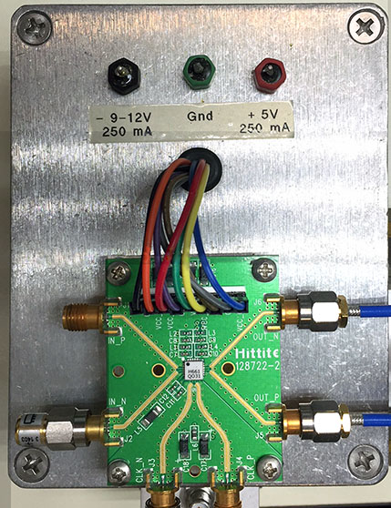
-Pictures show that the channel enable LED was off, and current meter shows set current (50mA) instead of 0, which is what it would show if the channel was ON

That's why I say we're pretty sure it was off. In any case, this was destined to happen. One time we would actually forget to turn the supply off or something like that and it would have blown off anyway.
You could easily forget that you first disabled PSU before disconnecting the wire as a first measure.  It's really hard to remember accurately when something like this happens. The only way to be sure would be only if you were taking video during the incident.

LOL you make me doubt now XD. The workbench we use has a table covered in antistatic mat, a zone for some instruments, a shelf for more instruments and an upper shelf where we tend to place boxes and the like. We intentionally placed the power supply in the upper shelf in a corner, to keep it as far off reach as possible to avoid accidentally touching the dials or something. I'm pretty sure I didn't have time to reach the supply before noticing it was off. My colleague says he remembers me stretching my hand to reach the supply, stopping in mid air pointing at the damn thing and saying "it's off... it's f*ing off" (not with those exact words, I curse in Spanish).

Now you'll ask how long the power supply wire is. Well, close to 1 meter. It's provided with the evaluation kit, the manufacturer says you should use it. Recommends remote sense PSU to compensate for losses in wire. We should've cut it, I know. But we decided to act as per the provided instructions.


You could easily forget that you first disabled PSU before disconnecting the wire as a first measure.  It's really hard to remember accurately when something like this happens. The only way to be sure would be only if you were taking video during the incident.

That seems like quite a stretch.  If something blows up just as you're plugging it in, your attention isn't going to wander back to the power supply button.  You're going to yank the connector out.

This is how I deal with $1000 eval boards with goofy power requirements and no supply conditioning:


The box just contains a couple of 3-terminal regulators.  Nothing fancy, but they can save the chip from most mistakes made by the board designer, the PSU, or me.  :-BROKE


We quite often work with GaAs MMIC's that require several power rails (some even 7 or more), both positive and negative, to be sequenced while controlling voltage and current, or else they blow. We ended up designing our own scriptable "voltage sequencing board" to avoid goofing up and blowing these devices. It contains several digitally adjustable regulators and load switches, all of them with current and voltage metering and a mircrocontroller to control the thing, and also some protection. You just load the on/off/desired working point script and press the ON button. It's been already amortized several times so far.


Offline Damianos

  • Frequent Contributor
  • **
  • Posts: 268
  • Country: gr
Re: Disabled power supply blows up expensive board... how?
« Reply #56 on: January 14, 2018, 01:59:10 pm »
... ...
Watching - I like detective stories
Enjoy it! But it seems more like a boring comedy...
Maybe the culprit is the material of the power supply feet! Are they of plastic or rubber? We have to analyze this!

From the initial description, it seems that was a user fault. They had to test a sensitive device, so they used a power supply with remote sense. But, instead of having fixed connections for this, they decided to connect it "on fly"! The consequences are known...

We connected it on the fly to avoid any startup surprise with the supply. I thought it was more reasonable to first power-up the supply, set it up properly and then, after it's properly setup, connect the board and finally enable the output channel.

I thought it was much safer to plug in the board with the supply in a known state and with its dials locked than to press the AC switch button with the board plugged in. Moreso in this case, where there's nothing between a 1000€ IC on a 10000€ board and the supply itself. We used the remote sense not because we liked the idea (it's idiotic not to have local regulation on-board) but because it was the manufacturer's recommended way of doing things. I didn't like the idea from the very beginning, also considering that the IC can draw current in pulses.

Now that the board is ruined, if we get a replacement or if we fix this board we'll hack it off either way and install a "modchip" that I designed with proper local regulation and protection.
I don't think that is a good idea to inflate the tires of your car while driving on the highway! It is not safer than to stop in a car-station, turn off the engine, activate the parking brake ...

You have already discovered what happened, in the update of the first post:
... ...
EDIT:

Here's an update. During this time we tried simulating the board with a dummy load, consisting of an electrolytic capacitor with similar specs to those of the tantalum that blew up (electrolytics can tolerate much more without blowing up with toxic smoke) and found some interesting things.

If you proceed exactly as we proceeded when the incident happened (power supply channel turned off), nothing happens. The output stays at 0V, no transient, no nothing. No matter how you connect the supply to the dummy load, nothing happens. If the capacitor is pre-charged it just discharges with a nice exponential curve (so the output has confirmed bleeding resistors)

If you then turn on the supply with the dummy load already connected, the output just rises nicely to 1.8V, no overshoots or weird stuff.

BUT, if you turn on the power supply channel with the dummy load disconnected and you then hot-plug the dummy load, in some cases there's a several 10's of volts transient (>40V), almost 3 seconds long, and then the output stays at 1.8V. That scenario would have explained our issue... if it wasn't for the fact that the PSU supply channel was disabled. We triple-checked that it was indeed disabled before plugging anything. Both my colleague and I are 100% sure that it was off.

We'll keep investigating... (the manufacturer hasn't answered yet, we'll try new communication channels).
The matter was that when you tried to connect the power with this connector, the sense voltage dropped, due to the uncharged capacitor and the power supply reacted by increasing the output voltage, to compensate for this. Then the rest of the pins connected, giving enough voltage/power to break/burn the components of the DUT...
BTW: does the power supply deactivated its output due to over-voltage detection?

As you are continuing "playing" with this thing, try to adjust the over-voltage protection (if exists) for example to 2V and repeat the experiments. You may find something interesting...
 

Offline KrudyZ

  • Frequent Contributor
  • **
  • Posts: 278
  • Country: us
Re: Disabled power supply blows up expensive board... how?
« Reply #57 on: January 14, 2018, 04:12:24 pm »
I still think that no reputable PS should allow its output to go beyond a fairly small voltage delta above the setting for that channel, no matter what you hook up to the sense wires.
A quick test on this supply could check for that.
Externally apply a small negative voltage to Vsense+ relative to ground and see how it reacts.
When looking at the published schematics for the CPX200 this would lead to an unlimited output,since the external sense pin bias would completely override the internal connection between the output and the sense. (They might have fixed this in the D model)
If the OP's supply indeed behaves like this, then it probably doesn't belong in a lab.
 

Offline xygor

  • Regular Contributor
  • *
  • Posts: 227
  • Country: us
Re: Disabled power supply blows up expensive board... how?
« Reply #58 on: January 14, 2018, 07:30:48 pm »
I still think that no reputable PS should allow its output to go beyond a fairly small voltage delta above the setting for that channel, no matter what you hook up to the sense wires.
...
Necessary, but not sufficient.  The hookup wire inductance could still be a problem.
See
http://cds.linear.com/docs/en/application-note/an88f.pdf


Share me

Digg  Facebook  SlashDot  Delicious  Technorati  Twitter  Google  Yahoo
Smf