Author Topic: DIY Power Supply/Ideas/Advice?  (Read 15548 times)

0 Members and 1 Guest are viewing this topic.

Offline JoshuaTopic starter

  • Regular Contributor
  • *
  • Posts: 194
  • Country: us
DIY Power Supply/Ideas/Advice?
« on: April 17, 2011, 03:02:02 am »
Hello everyone,

I asked another question in a different category about some project ideas, and got some really great responses. (Thanks Everyone!)

I have decided to make a DIY power supply, and looking for some ideas, advice, etc...

Here are some things that I feel like I DEFINITELY want...

-An LCD Screen that shows 1)Real-time voltage output, 2)Real-Time current output 3)Current limit setting
-Variable voltage
-Variable Current Output


Here are some things that I am not sure about and am looking for some information or advice on whether or not it is necessary

-Negative Voltages?
-How much current output do I need?
-What should my voltage range be?
-Should it go down to zero volts?


In the National Datasheet, there is the schematic below for a 5A variable voltage/variable current output.

Is there any reason why this shouldn't work?
How would I modify it for displaying the voltage/current as listed above?


I am not set on using the lm317, I am open to anything.


Any advice and ideas is greatly appreciated!!


Thanks so much in advance,
Joshua
 

alm

  • Guest
Re: DIY Power Supply/Ideas/Advice?
« Reply #1 on: April 17, 2011, 02:45:11 pm »
Negative voltages: as long as the output is fully floating, you can ground any of the output terminals, which will result in positive or negative voltages. If you want both positive and negative voltages, make a dual power supply (simple case: just build everything twice). If you want to get fancy, you could add auto parallel/series operation.

Amount of current: depends on your applications, there is no universal answer. Motors can draw lots of current, modern uC circuits draw very little. For my own projects, 1A is usually plenty, and I rarely need more than 12V. I do sometimes need 1.2V for some digital circuits, though. But someone into robotics or audio amplifiers will have completely different requirements, and someone into tubes will want a supply that goes up to 300V or so. I consider going down all the way to 0V an essential feature.

If it's in a National datasheet, I find it unlikely that it won't work. You do have to keep in mind that they tend to be designed to showcase their part. I dislike these kind of applications of three-terminal regulators. The advantage of these parts is few external parts and robustness (they're protected against too much current, too much power, too high temperature and almost anything you can think off except over voltage). Once you start adding an external pass transistor and external op-amp, you might as well do a discrete design with op-amps and transistors. The external pass transistor means you give up most of the protection features of the LM317.

The design used in most high-quality linear variable voltage/current supplies uses a constant current source to feed the pass transistor/Darlington, with two op-amps (one for voltage, one for current) that can sink this current to decrease the base current, and two diodes to make sure only one of them will be active at the same time. The supply of the op-amps is floating around the output voltage, which helps transient response. A simplified version is shown in HP AN-90B, under constant voltage/constant current (CV/CC) power supply. ELV has a complete schematic, schematics in German are similar to schematics in English ;). It is somewhat more complex that the design you posted, however.

Another design often used in cheap commercial bench supplies is with the LM723. This is a fine regulator for constant voltage operation, but not so great for constant current.

I would consider paralleling multiple pass transistors (with separate emitter resistors) for 5A. The advantage is that you spread the heat over a larger area of the heat sink, and that you decrease thermal resistance by paralleling the thermal resistances of the transistors (thermal resistance in parallel behaves just like electrical resistance in parallel).

To add voltage/current measurements to the schematic you posted, I would measure the voltage between the output terminals, and the voltage over R3 should be (almost) proportional to the output current. You could also add an ammeter in series, of course, but this would increase the output impedance.
 

Offline cyberfish

  • Regular Contributor
  • *
  • Posts: 240
  • Country: gb
Re: DIY Power Supply/Ideas/Advice?
« Reply #2 on: April 18, 2011, 12:57:16 am »
Is it just for learning, or to save money?

If it's to save money, no, it won't work. I tried designing my own, too, because commercial power supplies are expensive. Then after doing all the design, I realized it will cost more than a commercial unit with the same features.
 

Offline Hypernova

  • Supporter
  • ****
  • Posts: 655
  • Country: tw
Re: DIY Power Supply/Ideas/Advice?
« Reply #3 on: April 18, 2011, 08:29:03 am »
Look up TI's OPA54x series opamp that can source up to 8A, it has built in current limit where you set it with an external reference. TI's data sheet gives you an example with digital controlled PSU using two DAC's to control the thing. As usual you need a -v rail so that the opamp can swing to 0v output. You give up more bandwidth if you choose the higher current models.

It's about as close as it gets when it comes to an all in one solution at such power and size.
« Last Edit: April 18, 2011, 08:33:31 am by Hypernova »
 

Offline david77

  • Frequent Contributor
  • **
  • Posts: 934
  • Country: de
Re: DIY Power Supply/Ideas/Advice?
« Reply #4 on: April 18, 2011, 10:50:43 am »
Cyberfish is right, you will not save a penny by building a PSU yourself if you just go out and buy all the parts new. The most important and most expensive part will be the transformer.
Some creative thinking can save a lot of money here. Where are transformers used that you can use to make a nice poer supply? For example in old stereo HiFi amplifiers. An amp with an output of say 50-80W per channel should have a nice transformer in it that you could use. I'd expect something like 2x30-50V/3-5A.
You can pick those old amps up for a few bucks. Additionally they will have nice high capacity caps in them as well.
The next expensive thing is the enclosure. Why not make one yourself? I like to use aluminium profiles you get in any good DIY store and copper clad circuit board. Easy to work with, cheap and quite strong.
You will need huge heatsinks anyway (at least with a linear supply), there's not much chance getting around that. So choose wisely and you may be able to use the heatsinks as part of your enclosure.

The metering is a bit tricky. There are all sorts of traps regarding isolation from the output voltage of your PSU and so on. You can use cheap readily available 3,5 digit panelmeters, the cheap ones will need their own isolated power supply! You can build panel meters yourself using the ICL7106/7107 or you can whip something up using a microcontroller and a LCD module.
My own experience tells me to either use 3,5 digit modules or simple analogue meters. Though good analogue meters are not cheap at all, it is the simplest solution.

Some (no, a lot of) care needs to be taken with the mains side of things, basically good insulation, mains rated cable, plugs, switches, fuses have to be used. Keep all live parts well clear of the secondary side of the supply. Isolate all contacts with heat shrinking tube or cover them to prevent accidental touching. Connect all metal parts of your enclosure to protective earth! A lot of it is just common sense. 230V (or 115V) AC is not something to take lightly. It bites awfully and may kill someone!


Offline JoshuaTopic starter

  • Regular Contributor
  • *
  • Posts: 194
  • Country: us
Re: DIY Power Supply/Ideas/Advice?
« Reply #5 on: April 19, 2011, 02:53:53 am »
Negative voltages: as long as the output is fully floating, you can ground any of the output terminals, which will result in positive or negative voltages. If you want both positive and negative voltages, make a dual power supply (simple case: just build everything twice). If you want to get fancy, you could add auto parallel/series operation.

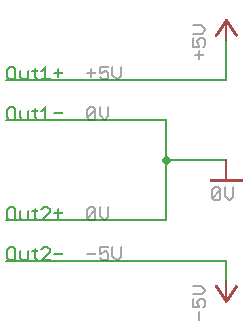
Ok, let me make sure I understand this right. I can basically build two power supplies, and connect them in series. Then, if I call the middle point(where the two are connected) 'ground', then the negative supply of one of the power supplies is -5 volts, while the positive supply of the other is +5 volts(assuming that both power supplies are set to output five volts) Is that correct? If so, does the following schematic(simplified of course) represent this (conceptually) accurately?


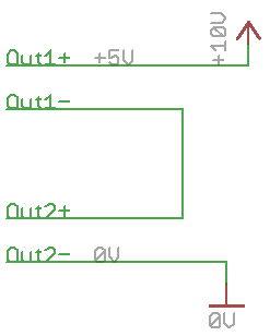
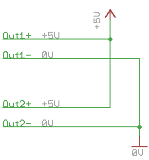
Is it relatively accurate to think of two power supplies as batteries? Putting them in series adds the voltage of the two, while putting them in parallel will keep the voltage the same but allow you to increase the current draw?   Do the following represent this?


Amount of current: depends on your applications, there is no universal answer. Motors can draw lots of current, modern uC circuits draw very little. For my own projects, 1A is usually plenty, and I rarely need more than 12V. I do sometimes need 1.2V for some digital circuits, though. But someone into robotics or audio amplifiers will have completely different requirements, and someone into tubes will want a supply that goes up to 300V or so. I consider going down all the way to 0V an essential feature.


I didn't think of it this way. Since I am still learning, I haven't really found an area I like to 'specialize' in yet. However, I can say that I know I will be dealing with motors(robotics and whatnot), and audio circuits at some point, if not in the somewhat near future.

My question is, how do I go down to 0 volts if all the regulators I've looked at(not all that many) must have at least something like 1.2 volts above output voltage to work on?

The design used in most high-quality linear variable voltage/current supplies uses a constant current source to feed the pass transistor/Darlington, with two op-amps (one for voltage, one for current) that can sink this current to decrease the base current, and two diodes to make sure only one of them will be active at the same time. The supply of the op-amps is floating around the output voltage, which helps transient response. A simplified version is shown in HP AN-90B, under constant voltage/constant current (CV/CC) power supply. ELV has a complete schematic, schematics in German are similar to schematics in English . It is somewhat more complex that the design you posted, however.


Thanks for the links. I am reading the app notes about power supply and am learning quite a bit I think...   

What makes the HP version simplified? What other 'stuff' would I need?


Is it just for learning, or to save money?

If it's to save money, no, it won't work. I tried designing my own, too, because commercial power supplies are expensive. Then after doing all the design, I realized it will cost more than a commercial unit with the same features.

I am not doing this to save money, solely to learn. (Well, I don't have a bench PSU) I am fine with buying what I need(as long as it's not crazy expensive), because I'd rather learn, than take the cheap way out. Thank you for the heads up, nonetheless.


Look up TI's OPA54x series opamp that can source up to 8A, it has built in current limit where you set it with an external reference. TI's data sheet gives you an example with digital controlled PSU using two DAC's to control the thing. As usual you need a -v rail so that the opamp can swing to 0v output. You give up more bandwidth if you choose the higher current models.

It's about as close as it gets when it comes to an all in one solution at such power and size.


This looks like it might be a nice way to do what I want. If what I said about negative voltages above is correct, how would I get a v- rail, without building two other power supplies, just so this one can work? (sorry for the newbie questions, I just really want to understand it, and not just hope it works, because I followed the schematic and hooked it up right)


The metering is a bit tricky. There are all sorts of traps regarding isolation from the output voltage of your PSU and so on. You can use cheap readily available 3,5 digit panelmeters, the cheap ones will need their own isolated power supply! You can build panel meters yourself using the ICL7106/7107 or you can whip something up using a microcontroller and a LCD module.
My own experience tells me to either use 3,5 digit modules or simple analogue meters. Though good analogue meters are not cheap at all, it is the simplest solution.

Some (no, a lot of) care needs to be taken with the mains side of things, basically good insulation, mains rated cable, plugs, switches, fuses have to be used. Keep all live parts well clear of the secondary side of the supply. Isolate all contacts with heat shrinking tube or cover them to prevent accidental touching. Connect all metal parts of your enclosure to protective earth! A lot of it is just common sense. 230V (or 115V) AC is not something to take lightly. It bites awfully and may kill someone!


What about something like this?

http://www.allelectronics.com/make-a-store/item/PM-122/3.5-DIGIT-LED-PANEL-METER-200-MV//1.html

What is meant when it says 'can monitor own voltage'???

Are analog meters naturally better for this application? I prefer some form of digital read out-mainly because I think it is nicer, but if analog is better than, by all means I am not resistant to it.


Thanks for the advice about working with AC! I am, however, quite comfortable working with such voltages, as my father is an electrical engineer, and has always taught me good safe practices for things like insulation, and chassis grounding. However, have basically no knowledge about the actual AC circuitry isolation, like pcb design, or what kind of transformer is needed, etc...


Thanks everybody for your help so far! My goal is to have a nice power supply that will help me with my electronics hobby, while also learning a lot while making it. I am continuing to research and read up about various aspects of things, but still need some help on the above mentioned topics.

Thanks again,
Joshua


Offline cyberfish

  • Regular Contributor
  • *
  • Posts: 240
  • Country: gb
Re: DIY Power Supply/Ideas/Advice?
« Reply #6 on: April 19, 2011, 03:01:59 am »
To get negative voltage, the easiest way is probably to use a transformer with a center tap (http://en.wikipedia.org/wiki/Center_tap). Or have 2 transformers in series, and call the middle point ground.

There are other ways of generating a negative voltage - a buck converter, or charge pump. You can look them up if you are curious, but I feel a center tap is the best method in this case.
 

Offline david77

  • Frequent Contributor
  • **
  • Posts: 934
  • Country: de
Re: DIY Power Supply/Ideas/Advice?
« Reply #7 on: April 19, 2011, 03:39:28 am »
Analogue meters are not better or worse than digital meters, if done right both is perfectly usable.
Digital is easier and quicker to read, of course. Analogue meters do not need their own power supply and are usually factory calibrated, so no need for high precision resistors or shunts and the like. You just buy a 0-30V and a 0-5A unit and connect them parallel (V) and in series (A) with your supply's output.
There are also pre calibrated digital panel meters available, they are usually properly expensive, though.

Your diagrams and thoughts about connecting PSU's together are correct. It works pretty much like the same way as with batteries.

If you are thinking of getting into audio gear I'd advise you to set out for a dual supply from the start. Nearly all higher quality audio circuitry today needs a dual supply. Also if you want to get into robotics I imagine two independent voltages will help, e.g. 5V for any sort of digital circuits and 12 or 24V for motors, solenoids and so on.
In both cases a linear dual supply 2x0-30V/0-5A would be my choice, as a matter of fact that's what I've built years ago and still use.


Offline Ed.Kloonk

  • Super Contributor
  • ***
  • Posts: 4000
  • Country: au
  • Cat video aficionado
Re: DIY Power Supply/Ideas/Advice?
« Reply #8 on: April 19, 2011, 06:54:01 am »
+1 everything david77 said.

Can I add though if you are lucky enough to be able to build your own power supply(as I was), do yourself a favor and invest in a multi-turn control pot for setting the voltage. You won't regret putting it in a supply. I often use PS's I've made in the past with the ordinary 270 degree pot and they suck. My nice Altronics kit that came with the 10-turn as a optional extra is crash hot, and is always nice to come home to, if you know what I mean..

 :)
iratus parum formica
 

Offline EEVblog

  • Administrator
  • *****
  • Posts: 38471
  • Country: au
    • EEVblog
Re: DIY Power Supply/Ideas/Advice?
« Reply #9 on: April 19, 2011, 08:37:37 am »
Can I add though if you are lucky enough to be able to build your own power supply(as I was), do yourself a favor and invest in a multi-turn control pot for setting the voltage. You won't regret putting it in a supply.

Ditto.
IMO, a multi-turn pot is pretty essential.
Especially if you have a 0-30V supply. The standard "Coarse" and "Fine" single turn pots just don't cut it.
I don't know why most traditional lab supplies go to 30V, you rarely need over 12V, maybe 15V.

Dave.
 

Offline david77

  • Frequent Contributor
  • **
  • Posts: 934
  • Country: de
Re: DIY Power Supply/Ideas/Advice?
« Reply #10 on: April 19, 2011, 09:10:10 am »
True. I prefer a single turn pot in series with a 10-turn pot. That's proved to be very efficient.


alm

  • Guest
Re: DIY Power Supply/Ideas/Advice?
« Reply #11 on: April 19, 2011, 10:12:43 pm »
My question is, how do I go down to 0 volts if all the regulators I've looked at(not all that many) must have at least something like 1.2 volts above output voltage to work on?
The usual way is supplying the regulator with a negative voltage compared to the negative output terminal (let's call that 0V, since it's floating we can ground any one point of the circuit). I think there's an example in the (National?) LM317 datasheet of this. The op-amp solution also does this, since the op-amps are fed by a symmetrical supply grounded at the positive output terminal (eg. +/- 5V). If the output is 0V, the op-amp supply is -5V and +5V relative to this. This gives the op-amps some headroom (footroom?), and allows for the two Vbe drops of the pass Darlington (either monolithic or discrete). The usual way is to use a small transformer for the reference voltages (op-amps only need very little current). If the main transformer is a toroid, you may also be able to put a few windings around it to gain extra secondaries (experiment to figure out the number required for the voltage).

What makes the HP version simplified? What other 'stuff' would I need?
Compare it to for example the ELV schematic (just a relatively simple example of this principle, I'm sure there are plenty of others). The op-amps need to be switched so the limiting one always wins. If the supply is set for 12V/1A, and it's currently delivering 10V/2A, the voltage op-amp will try to increase the output voltage, and the current op-amp will try to decrease it. In the ELV schematic, this is solved by a constant current source (T1 and supporting circuitry), which supplies a constant current to the base of T2/3. Due to the diodes, the op-amps can only decrease the base current, and the diode will be reverse biased if the op-amp is outputting a positive voltage compared to the base voltage of T2/3. The HP/Agilent schematic also omits the compensation network around the op-amps, and the power supply of the op-amps. It's simplified to just show the principle of operation. If you want a more detailed schematic, these are available in some of their service manuals. One example is the E3620A manual (no link handy, should be easy to find on the Agilent site), just ignore all the triac stuff, it's just to make things more efficient and save on cooling.

What about something like this?

http://www.allelectronics.com/make-a-store/item/PM-122/3.5-DIGIT-LED-PANEL-METER-200-MV//1.html

What is meant when it says 'can monitor own voltage'???
With most panel meters, the voltage they monitor needs to be floating with respect to the module's power supply (i.e. you need a separate secondary transformer winding for each panel meter). This is because they bias the common terminal of the monitored voltage to something like 0.7V above the module's power supply. If it can monitor its own voltage, it shouldn't need the floating supply.


Are analog meters naturally better for this application? I prefer some form of digital read out-mainly because I think it is nicer, but if analog is better than, by all means I am not resistant to it.
Both have their advantages. Digital can be more accurate. Analog doesn't require messing with extra floating supplies and has a much higher bandwidth. Most digital panel meters update a few times per second at most. The needle can swing much faster. This makes it much easier to see fluctuating loads, and also gives you audible feedback when the current drops to zero. Analog panel meters tend to be expensive, though, maybe that's the reason why they're rarely seen on commercial supplies these days. Some people still prefer the analog ones.
 

Offline JoshuaTopic starter

  • Regular Contributor
  • *
  • Posts: 194
  • Country: us
Re: DIY Power Supply/Ideas/Advice?
« Reply #12 on: April 22, 2011, 03:26:16 am »
Thanks for the reply everybody!


A couple of more questions...

I read through the HP Power Supply Link, and learned a lot. I understand the voltage regulator example that uses a transistor as a series regulator. (The simplified version of the ELV)

I understand how a person uses this to control voltage output, but how do you limit current with this?

For this power supply (I have decided to make a dual supply), what are the pros and cons of current limit vs. constant current? Which should I build?

Also, how do you get from the HP schematic to the much more complex ELV schematic. I could understand it if it was put into chunks and was added on the example piece by piece. However, It's just to much for me to understand right now. Is there any information regarding the function of the rest of the circuit?


I might be getting ahead of my self, but would it be possible to put a micro inside, and instead of a ten turn pot, what about a digital pot with a rotary encoder. I figure you could make it that the faster you turn the encoder, the larger the steps of resistance of the digi-pot. If you turn it really slowly, you get really fine adjustment. Any thoughts?

I feel like once I get a basic design, then it won't take as much time, but since I am trying to learn and understand it as well it's taking a bit longer to get to that point.


Thanks,
Joshua


Share me

Digg  Facebook  SlashDot  Delicious  Technorati  Twitter  Google  Yahoo
Smf