Author Topic: Driving a Synchro from a uC  (Read 3970 times)

0 Members and 1 Guest are viewing this topic.

Offline fsedanoTopic starter

  • Contributor
  • Posts: 19
  • Country: ch
Driving a Synchro from a uC
« on: September 20, 2017, 01:53:48 pm »
Hello folks,

This topic has been discussed but didn't find any conclusion - Wondering if I could get a hand. Looks like a simple thing but I'm running out of ideas;

I'm trying to drive this aircraft instrument:


The connections inside it are like this:


That is, one of the terminals on the rotor is connected to one of the terminals in the stator.

Knowing the waveforms generated when the rotor is excited, as per:


What I tried so far is connecting half-H bridges to each one of the terminals (1,2,3,4), and drive them with a PWM-based Sin as follows


1) and 2) are complimentary outputs of generator 1
Generators 1, 2 and 3 share same timer, so same initial phase and frequency.

I drive all outputs with a 400 Hz sin, modulated as follows, being alpha the desired pointer angle

PWM1 = sin(alpha)*(400Hz signal)
PWM2 = sin(alpha+120)*(400Hz signal)
PWM3 = sin(alpha+240)*(400Hz signal)

What it's confusing me is the fact one of the stator windings is tied to one of the rotors.

With this setup, I get some movement but it's not OK. On this video, I'm moving the desired angle from 0 to 360:


I tried this setup with two similar instruments:


and the current consumed by both synchros was about 80mA. On my experiment you can see power supply is limiting the current to 300mA, so something's not quite right.

Ideas?

Thanks!!


Offline capt bullshot

  • Super Contributor
  • ***
  • Posts: 3033
  • Country: de
    • Mostly useless stuff, but nice to have: wunderkis.de
Re: Driving a Synchro from a uC
« Reply #1 on: September 20, 2017, 02:05:38 pm »
You're driving the rotor with an amplitude modulated signal. You'd need a constant amplitude here.

Not the inverted PWM1 signal but something like (I may be wrong with the equations, hope you get the point)
PWM4 = (1-sin(alpha))*(400Hz signal)
PWM1 = sin(alpha)*(400Hz signal)
Safety devices hinder evolution
 

Offline fsedanoTopic starter

  • Contributor
  • Posts: 19
  • Country: ch
Re: Driving a Synchro from a uC
« Reply #2 on: September 20, 2017, 02:24:22 pm »
Thanks!

So your proposal is to compensate the amplitude change I'm doing, right? However, isn't that going to impact the stator signals?

I'll give it a try and report back ;)

Thanks,
 

Offline fsedanoTopic starter

  • Contributor
  • Posts: 19
  • Country: ch
Re: Driving a Synchro from a uC
« Reply #3 on: September 20, 2017, 10:29:30 pm »
No luck :(

Just to simplify things a little, I used a different synchro, which does not have the connection between stator and rotor, using same equations:

Rotor: constant sin(400hz)

On each of PWM modules, 1/2 H bridge towards the stator connection. Equations as described, sin(angle)*400hz

Power consumption is small now, but movement is random :(


Online Andy Watson

  • Super Contributor
  • ***
  • Posts: 2084
Re: Driving a Synchro from a uC
« Reply #4 on: September 20, 2017, 11:16:03 pm »
How are you changing the drive to stator coil that is linked to the rotor? Note that to go "full circle" there must be some point at which the drive to the stator coil changes to 180 degrees out of phase with the rotor drive. I don't think you can achieve this (easily) if the rotor and stator drives operate from the same power supply - i.e. they need to be isolated to attain the phase inversion.


Offline David Hess

  • Super Contributor
  • ***
  • Posts: 16607
  • Country: us
  • DavidH
Re: Driving a Synchro from a uC
« Reply #5 on: September 20, 2017, 11:24:17 pm »
Check that waveform drawing again.  The phase to the stator coils is always a multiple of 180 degrees; they are driven either in-phase or out-of-phase.  The relative amplitudes control small increments of position.
 

Offline duak

  • Super Contributor
  • ***
  • Posts: 1041
  • Country: ca
Re: Driving a Synchro from a uC
« Reply #6 on: September 21, 2017, 01:54:38 am »
For a quick test, I would disconnect the rotor lead connected to phase 1 and tie it to the half driver DC common through a capacitor.  This would apply a constant AC reference voltage to the rotor and allow the phase 1 voltage to be varied independantly.  A capacitor is needed to block the average DC voltage on phase 2 and should be something like 100 uF.

It should be possible to make the original circuit work with some inventive math.  I recently heard that one phase of some aircraft electrical systems is tied to the airframe to minimize wiring.  It could be that the indicator that has the rotor tied to one of the phases is set up for this configuration.  Because this is a PWM driver that has to be switching and not a 3 phase generator that can have one of its nodes grounded, phase 1 will driven to full amplitude, ie. not modulated, and the other phases referenced to it.  Phases 3 & 4 need different drive signals to compensate for the full amplitude signal on phase 1.  Providing I get the math right, phase 3 will be sin(theta + 120) - 1/2*sin(theta) and phase 4 will be sin(theta - 120) - 1/2*sin(theta) where theta is the desired angle to be shown on the indicator.  If memory serves, the signals on phases 3 & 4 are 180 deg out of phase with each other and 90 deg out of phase with phase 1.  Look up "Scott-T connection"

Hope this makes sense.  If I'm wrong, maybe someone else will chime in?


Offline hlavac

  • Frequent Contributor
  • **
  • Posts: 536
  • Country: cz
Re: Driving a Synchro from a uC
« Reply #7 on: September 24, 2017, 04:31:02 pm »
I have a feeling something is not right with this PWM scheme...  ???

You dont seem to have any filtering on the pwm outputs.
So the winding ends see only min and max voltage as they are pwmed.
Windings are connected in star configuration, the midpoint has no connection.
Any current has to go through two windings in series.
So the actual driving waveforms should be a weird mix of the pwm signals no? :scared:
How exactly do the pwm signals look like???
Good enough is the enemy of the best.
 

Offline eagle_wen

  • Newbie
  • Posts: 1
  • Country: be
Re: Driving a Synchro from a uC
« Reply #8 on: March 20, 2018, 09:02:27 pm »
Hi,

did you ever get this to work?

I'm trying to control 3 synchro receivers from a Horizontal Situation Indicator. Each synchro receiver is driving a drum wheel for the number of miles with the distance from the beacon.

I would appreciate it if you have solved this and you want to share this with me.

Thanks
Werner
 

Online Andy Watson

  • Super Contributor
  • ***
  • Posts: 2084
Re: Driving a Synchro from a uC
« Reply #9 on: March 21, 2018, 07:50:52 pm »
I'm trying to control 3 synchro receivers from a Horizontal Situation Indicator.
How are your synchos wired? The problem with the OP's synchros is that one of the phases shared a connection with reference winding - i.e. there is no method of generating a full 360 degrees of torque with just three drive signals.
 

Offline C

  • Super Contributor
  • ***
  • Posts: 1346
  • Country: us
Re: Driving a Synchro from a uC
« Reply #10 on: March 21, 2018, 08:50:31 pm »
First need to think correctly.

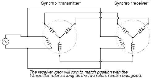
Old Synchro systems could be thought of as a rotary tramsformer.

The sender
Power is from a 400hz source.
The rotation of the shaft changes the ratios of the three phase signals.

When connected to receiver which is acting like a motor.
The 400hz supplies the rotor.
The three phase signals supply the rotation.
Because the foundation is 400hz, AC transformers function.
Because of the 400Hz modulation rotation can go to 0 change.

So the sender is sending a 400Hz modulated three phase signal.
To create this you need 400Hz source and create three signals with proper phase amplitude for current rotation angle.


Edit again
You should note that when suppled with 400Hz the indicator will have the current rotation angle encoded on the three phase windings.

with out phase amplifiers, torque is coupled between shafts.
Change one shaft rotation and other shaft changes rotation. Proper phase amplifiers will let you control torque as a ratio between shafts. 
« Last Edit: March 21, 2018, 09:29:17 pm by C »


Share me

Digg  Facebook  SlashDot  Delicious  Technorati  Twitter  Google  Yahoo
Smf