Author Topic: Driving wide format CRT from old Word Processor (or how to find a Z80 computer!)  (Read 8334 times)

0 Members and 1 Guest are viewing this topic.

Offline richfilesTopic starter

  • Regular Contributor
  • *
  • Posts: 156
  • Country: us
So, I've been doing other things as I wait for my FDAI controller parts to arrive on a slow boat from China. https://www.eevblog.com/forum/projects/trying-to-emulate-three-synchros-using-arduino/

What has caught my eye is this fully functional Brother WP-2450DS "Portable" word processor. I was thinking of issuing the CRT an eviction notice.  :-DD


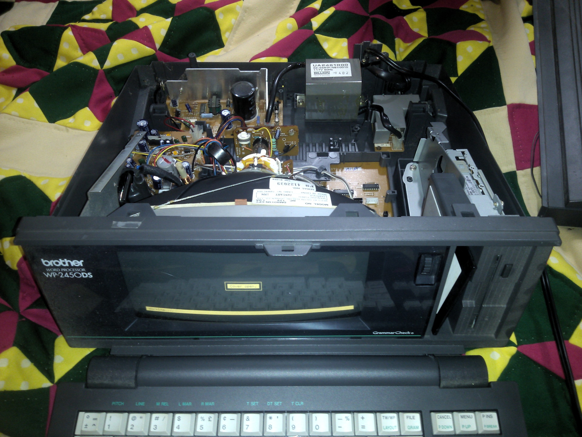
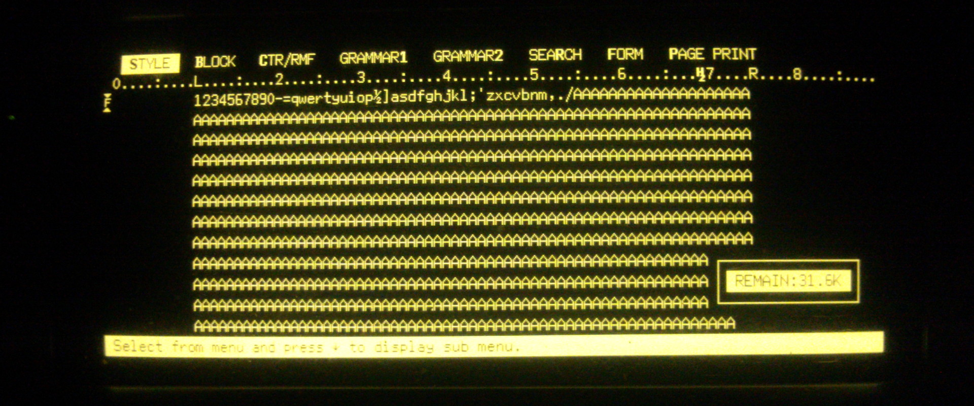
As you can see, it has a very wide format amber monochrome CRT that is screaming for a chance to be used on Some Random Projectâ„¢! It measures approximately 8 x 3.5 inches (19.6 x 8.6 cm), and the thing has no dust, no burn in, no nothing... It looks like it was bought and then never used. This would be a very late model stand alone word processor as well, as the 1994 dates inside indicate it was made very close to the end of the run for this type of non PC word processor. I'd like to repurpose this for something. If I could get graphics to display on it, I'm considering using it to do something like an orbit visualizer. Now that the Kerbal Space Program telemetry plug-in outputs SoI (Sphere of Influence), I can potentially display the current SoI and render the orbit based on the already existing orbital data. It would not be particularly advanced. A circle to represent the body being orbited, with maybe a line through the equator or a crosshair to represent the poles, and a circle/ellipse/arc representing the orbit. I'd display it as two views (top down and edgewise, each side by side).

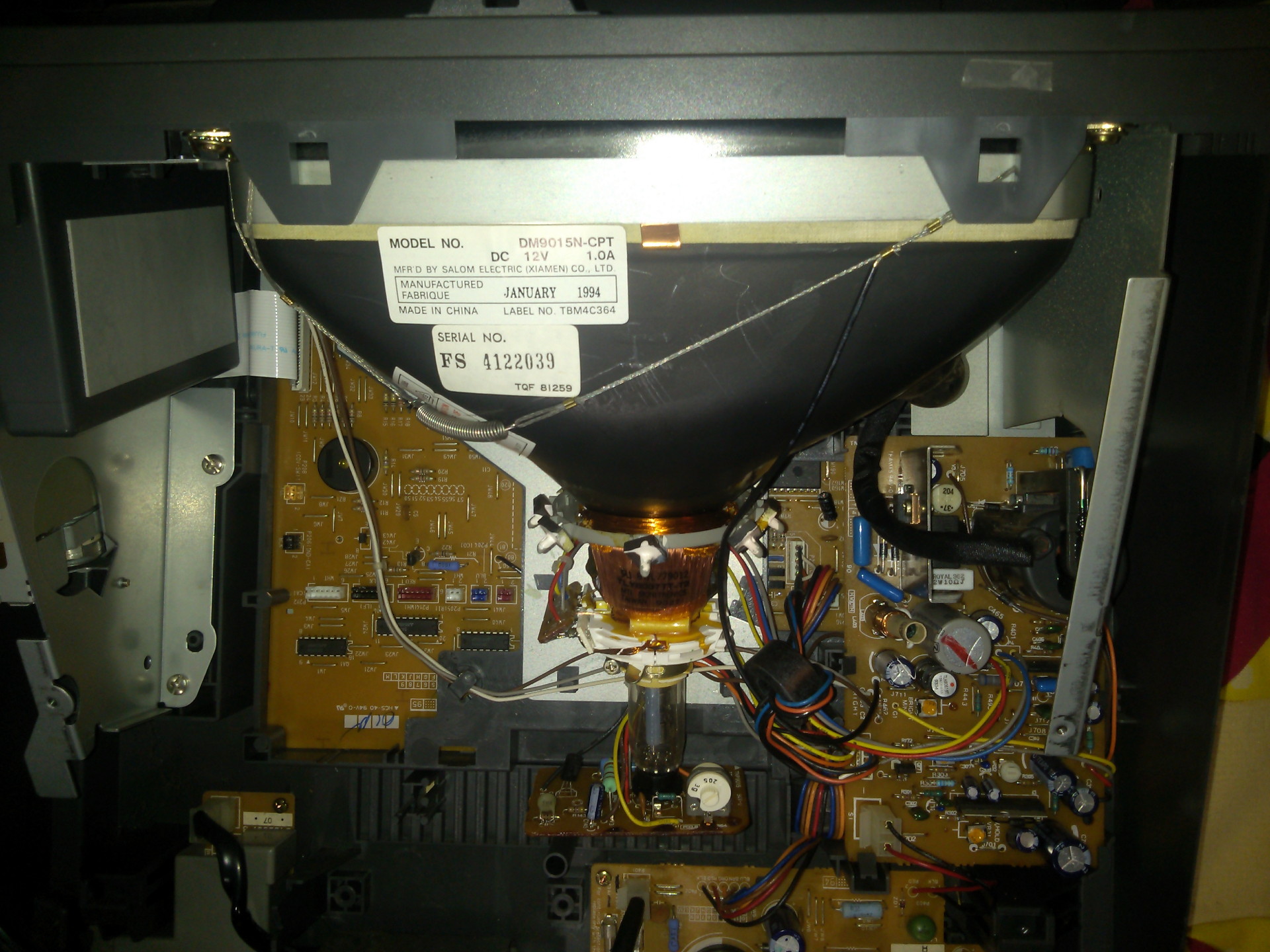
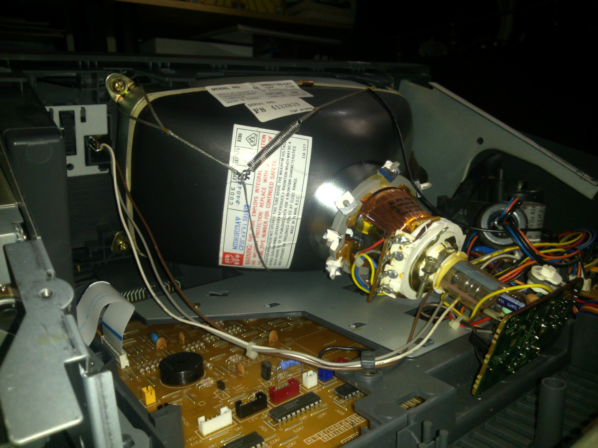
The catch is, I don't have a good way of driving this thing yet. I've looked at it visually so far (today has been my first day off in a while, but my scope's triggering is wonky lately... NEED to replace it). It has 3 signal wires. The three signals are fed through some inductors and resistors, and that leads directly to a programmable logic array being used as the word processor's "processor". The good news is that means It's likely a TTL driven video signal, and I can just desolder the couple analog components to recreate the signal conditioning circuit, exactly. There appears to be a 3 pin component, also listed as an "L" part on the silkscreen. Possibly an inductor with a center tap? The problem is in actually driving the signals themselves. Since the chip is a custom ASIC design, programmed into a logic array, it means I have no "video chip" to hack. I have to BUILD the video driver from scratch. It's almost certainly likely that with as small and simple as the monitor's PC board is (it's the small rectangular board to the right of the CRT, viewed from behind), that the three signals are horizontal sync, vertical sync, and the actual video stream. The word processor has no external I/O either, and likely has no "terminal" function.


In order to figure this out, I'm going to have to measure the signals using an oscilloscope. I'll need to measure the timing for both the horizontal and vertical sync, and measure the timing for the pixels too, along with the blanking period. Until I do this, I don't know the frequency it refreshes at, nor the scan rate for pixels. I have to go down to the machine shop I work at to finish an assembly (for one of my two jobs). I think I'm gonna bring this thing with me and pop it on the scope there, after I'm done actually working. Since my scope is acting up, It'll be simpler to do it this way. I'll solder some extensions to those 3 wires, plus ground so I can measure it more easily. It appears to be at least an 80 column display, so even though it's reduced height, it'll be pushing a rather high pixel rate per horizontal line. Each character on the screen (with the original controller) is 8 pixels wide (including the gap between letters). That means this monitor probably has a 640 pixel horizontal line resolution. I'm guessing the vertical resolution is around 300, give or take a dozen or two pixels. Hard to tell from the large blank spaces between lines. The Arduino TV out libraries don't exactly come close to this resolution. Even if this updates at only 30 Hz, that's still over 5.7 million bit flips per second, over 11.5 million if it refreshes at 60 Hz. That's really pushing an Arduino. They only run 16 MHz anyway. I might look into an Arduino Due, as I understand they are much faster. I only need to deal with monochrome, but there is a lot of bits to deal with for 640x300-ish. I might also look into some older style hardware. If I can find an old chip/chipset from an 8-bit/16-bit era computer that actually handles generating the video signals and maintaining the video memory, then I might try to make something like that instead, so I can just send data updates to it, and have it handle everything. I might also try a hardware based setup. I have TONS of CPLD chips that I can program logic hardware in. I can also scavenge some pseudo SRAM chips (DRAM that entirely contains the refresh circuitry, and interfaces like SRAM) from the Word Processor board and create a scanable video memory. That might be another viable way to go about doing this. If I do it right, I might be able to do a proper bitmap, and display graphics on it.


The Arduino TVout library only seems to generate composite sync signals (not to mention has a sad resolution). I also don't need any type of color support, so the tricks to send out extra bits with port writes doesn't help, as I still need them streamed sequentially. There is a VGA library that uses external hardware, but again, I have no need for color, and I don't know if the timings can be readily adapted easily. It'd be better for me to try a NON arduino based means of controlling this, as pushing an Arduino this hard seems like a bad starting point for someone just learning C.

I've actually been looking into a few retro CRT driver chips. I've found one can be had for under $10-20, seems common enough, can drive 80 column text mode, and do pixel addressable graphics, and has a rudimentary line, arc, box, and circle drawing capability as well. My problem, again, is programming inexperience. Nothing more, nothing less. It's gonna take me a good long while to even learn how to interface this chip. It's not as straight forward as I was hoping.

The NEC uPD7220
http://bitsavers.trailing-edge.com/pdf/nec/uPD7220-uPD7220A_User_Manual_Dec85.pdf

The other OBVIOUS thing... Is has anyone here ever done what I'm doing... Repurposed one of these wide format monochrome CRTs. I know the HP-87 computers used wide format CRTs, and some of these retro word processors. I really don't know of any other applications for them. If someone has already done hardware or code that makes it work, I'd more than welcome the advice!

So, yeah, that's what I'm thinking about while I wait for the FDAI parts to show up.


**NOTE**
Further reading is telling me that NEC chip takes a fair bit of external hardware to work... Sounds like it handles memory timing and generating the raster signals (horizontal, vertical, blanking), but that external DRAMs, multiplexers, etc are still used to create the actual video stream. Finding 8 or 16 vintage DRAM chips... Ugh...

So... recommendations are welcome.
« Last Edit: August 04, 2015, 03:15:15 am by richfiles »
 

Offline MyElectronsFellOut

  • Regular Contributor
  • *
  • Posts: 70
  • Country: gb
Re: Driving the wide format CRT from an old Word Processor
« Reply #1 on: August 03, 2015, 03:37:33 pm »
That looks like a project and a half.. There is something to be said for retro tech being re purposed for ones own requirements/amusement.  I will be interested to see how this turns out.   :-+
 

Offline MK

  • Regular Contributor
  • *
  • Posts: 234
  • Country: gb
Re: Driving the wide format CRT from an old Word Processor
« Reply #2 on: August 03, 2015, 07:55:46 pm »
Dont forget to save the discrete high voltage transistors, some of them are Toshiba FBET's very good for an audio amp in Vas duty due to the very low capacitance and high gain combined with a high early voltage, some are unobtanium now...
 

Offline richfilesTopic starter

  • Regular Contributor
  • *
  • Posts: 156
  • Country: us
Re: Driving the wide format CRT from an old Word Processor
« Reply #3 on: August 03, 2015, 09:30:55 pm »
Hmm... Not sure what you're talking about salvaging. I have no intention of scrapping any piece of the CRT and it's drive circuitry. That will remain fully intact, for my Kerbal Space Program "cockpit". The printer portion of the word processor (currently detached, and not in the image) is driven by M54587P and M5286P darlington drivers. I'll save those for driving motors in robots.
« Last Edit: August 03, 2015, 09:32:47 pm by richfiles »
 

Offline T3sl4co1l

  • Super Contributor
  • ***
  • Posts: 21674
  • Country: us
  • Expert, Analog Electronics, PCB Layout, EMC
    • Seven Transistor Labs
Re: Driving the wide format CRT from an old Word Processor
« Reply #4 on: August 03, 2015, 11:35:23 pm »
Manual: http://www.maisiemanuals.com/brother-word-processor-2450ds-parts-service-manual-p-1515.html

819 x 240 resolution, 5 x 9", 91x15 text (does that include rulers and stuff, or what?).  So characters are probably 8x16, fairly typical for text modes.

Aha, CPU = HD64180.  Seems to be, improved Z80 or such?  If you can get at the ROMs, just play with that straightaway! :D :D

Tim
Seven Transistor Labs, LLC
Electronic design, from concept to prototype.
Bringing a project to life?  Send me a message!
 
The following users thanked this post: richfiles

Offline tautech

  • Super Contributor
  • ***
  • Posts: 28368
  • Country: nz
  • Taupaki Technologies Ltd. Siglent Distributor NZ.
    • Taupaki Technologies Ltd.
Re: Driving the wide format CRT from an old Word Processor
« Reply #5 on: August 03, 2015, 11:47:55 pm »
I was thinking of issuing the CRT an eviction notice.  :-DD
:-+
 :popcorn:
Avid Rabid Hobbyist
Siglent Youtube channel: https://www.youtube.com/@SiglentVideo/videos
 

Offline T3sl4co1l

  • Super Contributor
  • ***
  • Posts: 21674
  • Country: us
  • Expert, Analog Electronics, PCB Layout, EMC
    • Seven Transistor Labs
Re: Driving the wide format CRT from an old Word Processor
« Reply #6 on: August 03, 2015, 11:54:39 pm »
Wow, they even give the pinouts, signals, descriptions, memory maps, everything short of register descriptions and signed source code! :o

You, sir, I do believe, have a tinkerer's dream -- not even a hacker's dream, there's nothing to be hacked!  Poke around with those ROMs (which are hopefully socketed, if not, desolder them and add your own, you'll need it!), download and disassemble, and write your own!

Looks like they don't have a character generator, rather the CPU copies from CGROM to VRAM.  Your orbital plotter sounds easier than EVER!  :-+ :-+ :-+

Tim
Seven Transistor Labs, LLC
Electronic design, from concept to prototype.
Bringing a project to life?  Send me a message!
 
The following users thanked this post: richfiles

Offline richfilesTopic starter

  • Regular Contributor
  • *
  • Posts: 156
  • Country: us
Re: Driving the wide format CRT from an old Word Processor
« Reply #7 on: August 04, 2015, 01:49:58 am »
Man!!! I gave up too quick looking for info on this thing! I feel SUPER DUMB! I'd been Googling for three DAYS before coming here! |O
But then again, that's why I came here! You guys rock! You've got a LOT more experience than I do. Thanks guys! :-+

Freakin' Z80, huh... Wow. I TOTALLY missed that! I don't know HOW either... It's ONLY the second biggest chip on the board. I'd been popping chip part numbers into Google and downloading datasheets... So again, HOW did I miss this BIG chip!?! Downloaded datasheets for the Gate array, the Ram, the ROMs, the motor driver ICs, the floppy controller... The only chips I didn't download a datasheet to was the CPU and the 7404... And I know what a 7404 does... :palm:

That's also a heckova wide resolution! I felt that it might be a bit wider than I'd guessed. I overestimated the vertical, but not by a lot.
 

Offline rodcastler

  • Regular Contributor
  • *
  • Posts: 98
  • Country: cl
Hi there, my apologies for the bump but this morning on my way to work one of these babies showed up on the sidewalk. (earlier model Brother WP-1 from 1985 though).
I just couldn't resist the wide CRT and picked it up. Machine + water + mud was uber-heavy.

No keyboard to be found nearby:  both power cord and keyboard cables were cut with a knife.

...

Brought it to the lab and fired it up....    ***********   AND HOLY SMOKES A WIDE AMBER CRT THAT WORKS !! TOTALLY WORTH IT *********

The main board offers a CRT controller HD6445 which has a character set, but seems way too overkill to try to interface with this chip directly.

My fellow friend I need your help: I  have no clue on how to interface this screen. It of course shows "KEYBOARD ERROR" and that's it.

I want to do it by emulating keyboard inputs. I followed the traces of the kbd connector and the two lines (I assume they are DAT and CLK) end up in what appears to be a proprietary die.

Please please scope yours and help me out with the keyboard protocol. The goal is to write from an arduino via keyboard emulation to the original motherboard (which is 80's beauty and in great shape btw).

I've been unable to find documentation on the keyboard protocol, nor schematics, nor manual for this particular model.

If anybody can contribute with documentation, I'd appreciate it.

Thank you!


PS: I googled several hours before even thinking of coming here and what do you know: Someone had already brought one of these machines to the EEVBLOG. unbelievable.

Edit: typos, typos.
« Last Edit: May 30, 2017, 02:00:15 am by rodcastler »
 

Offline james_s

  • Super Contributor
  • ***
  • Posts: 21611
  • Country: us
I have a similar word processor with that same weird super wide CRT, it's bizarre that they used a custom tube rather than just going with a standard 4:3 CRT.

I've thought about repurposing the monitor from mine too. I think I'd go with an FPGA based solution, I've got this driving a CGA CRT monitor.

http://searle.hostei.com/grant/Multicomp/
 

Offline rodcastler

  • Regular Contributor
  • *
  • Posts: 98
  • Country: cl
"it's bizarre that they used a custom tube rather than just going with a standard 4:3 CRT.

They may have been inspired by the CTC datapoint 2200. Standards were attempted to be defined back then I suppose.

Back to my keyboard challenge: The two communication wires are pulled up and stay that way according to my scope, which probably means that the clock signal is generated by the keyboard itself and the unit is waiting for it, hence the error. I wonder what chip is inside that keyboard.


Offline richfilesTopic starter

  • Regular Contributor
  • *
  • Posts: 156
  • Country: us
Hi there, my apologies for the bump but this morning on my way to work one of these babies showed up on the sidewalk. (earlier model Brother WP-1 from 1985 though).
I just couldn't resist the wide CRT and picked it up. Machine + water + mud was uber-heavy.
No keyboard to be found nearby:  both power cord and keyboard cables were cut with a knife.
Brought it to the lab and fired it up....    ***********   AND HOLY SMOKES A WIDE AMBER CRT THAT WORKS !! TOTALLY WORTH IT *********
The main board offers a CRT controller HD6445 which has a character set, but seems way too overkill to try to interface with this chip directly.
My fellow friend I need your help: I  have no clue on how to interface this screen. It of course shows "KEYBOARD ERROR" and that's it.
I want to do it by emulating keyboard inputs. I followed the traces of the kbd connector and the two lines (I assume they are DAT and CLK) end up in what appears to be a proprietary die.
Please please scope yours and help me out with the keyboard protocol. The goal is to write from an arduino via keyboard emulation to the original motherboard (which is 80's beauty and in great shape btw).
I've been unable to find documentation on the keyboard protocol, nor schematics, nor manual for this particular model.
If anybody can contribute with documentation, I'd appreciate it.

Looking over the service manual for my unit, shows that my keyboard is scanned as a matrix, by the Programable Logic Array chip, and that data is passed to the CPU. There is no serial keyboard interface on mine. 9 years is a huge difference for technology. Sorry, can't help.

These wide format small CRTs have definitely been available for quite some time. The HP 87 that I mentioned earlier in the thread, and the Datapoint 2200 both had wide format CRTs. They were around for at least a solid two and a half decades, till LCDs replaced them in small form factor devices. I think I've also uncovered the most likely reason for that particular screen size... I found a mention where CTC themselves "wanted a CRT with the same aspect ratio as an IBM punchcard"! It's quite likely that other manufacturers stuck with the particular CRT ratio for their own specialty applications for two primary reasons. For one thing... The CRT already existed, thanks at least to CTC. Secondly, it lends itself well to serving as a "paper wide" display, that doesn't waste unnecessary height, when scrolling is acceptable.


Interestingly enough, The Datapoint 2200 went on sale in 1971, and along with a wide format display, also had a small scale TTL implementation of what eventually became the original 8008's instruction set. TI and Intel were commissioned to develop an LSI 8-bit CPU on a single chip... TI dropped out after buggy samples. Intel didn't meet the deadline or the performance requirements. CTC agreed to let Intel keep the intellectual property rights for the instruction set to use for the eventually finished chip, and CTC used their own TTL implementation, keeping their $50000 investment money instead... :palm: And then the 8008 happened... and the 8086, and the 8088... and ultimately the entire line of x86 processors... You know CTC knew the true meaning of regret... |O

And since the original service manual link went dead, I'm adding a new link to download it. Hopefully it lasts longer than the original did.
https://mega.nz/file/jBwDFIpY#-KxYESB2pGhNLOxAoguuAYqu9jEbNoic61itndyoH18
« Last Edit: September 24, 2021, 10:54:07 am by richfiles »
 
The following users thanked this post: rodcastler

Offline legacy

  • Super Contributor
  • ***
  • !
  • Posts: 4415
  • Country: ch
Why don't we reinvent the computer instead?
It's what I am doing here (hobby)  :D


Share me

Digg  Facebook  SlashDot  Delicious  Technorati  Twitter  Google  Yahoo
Smf