Author Topic: ebay u-blox LEA-6T GPS module teardown and initial test  (Read 65089 times)

0 Members and 1 Guest are viewing this topic.

Offline GyroTopic starter

  • Super Contributor
  • ***
  • Posts: 9505
  • Country: gb
ebay u-blox LEA-6T GPS module teardown and initial test
« on: March 04, 2016, 07:46:03 pm »
Prompted by voltsandjolts's post in this thread:

https://www.eevblog.com/forum/projects/it's-feb-2016-which-ebay-gpsdo/msg875683/#msg875683

I decided to buy on of the u-blox LEA-6T GPS navigation modules currently available on ebay at under £20. It has duly arrived in 10 days flat to the UK from HK, complete with some mounting hardware and a micro-USB adapter board. This is the Timing version of the module, although for some reason being sold for drone use. Being the LEA variant, there are two programmable timing pulse outputs available.

The first thing to do was hook it up to the adapter board and try it with the u-blox u-center s/w available from their website. It works fine and appears very sensitive, getting a 3D lock downstairs in a 2 story house.

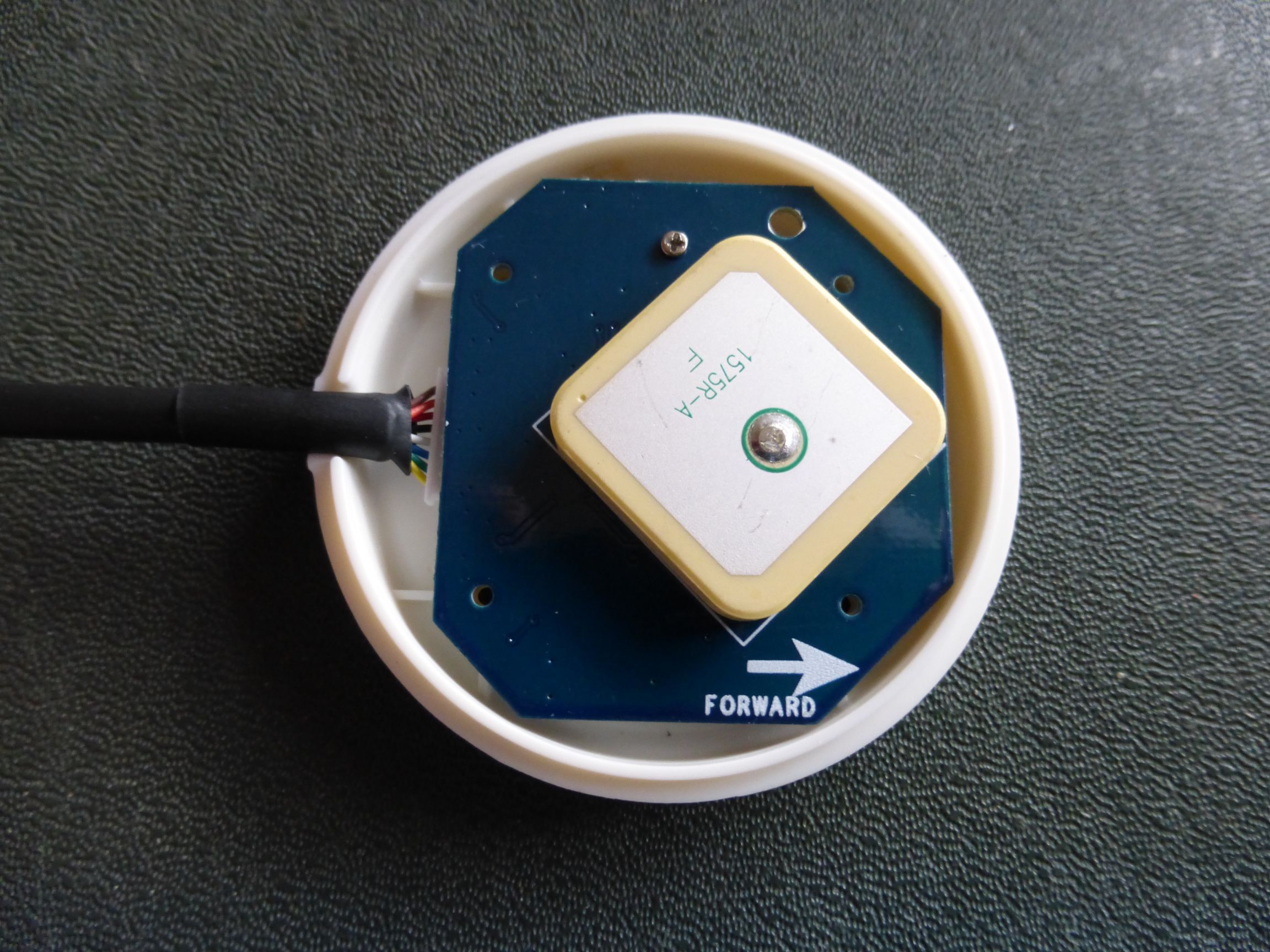
Time to pull it apart and work out the connector pinouts as I couldn't find anything on the web (there is documentation for 'Pixhawk' interfaces but these doesn't appear to match). The unit is held together with 4 screws with a further one locating the PCB in the bottom of the case to ease assembly. The top surface on the PCB is occupied by the 25mm passive patch antenna only:


On the bottom of the PCB is a u-blox LEA-6T-0-000, together with a compass IC, backup battery and other parts. This version of the LEA-6T is hard-coded rather than Flash based, but the board does include an ST 32k bit EEPROM for long term settings storage. The memory backup battery is rechargeable. There's an on-board 3V3 LDO regulator (taking the 5V supply from USB), also included are PTC and reverse polarity diode protection. There are also two LEDs, a red one on the 3V3 supply, and a green one, transistor buffered from the Timepulse signal.

The interface connector on the board has a pinout as follows:

Pin   Wire Color   Signal
1   Yellow      RXD1
2   Green      TXD1
3   Blue      Compass I2C
4   White      Compass I2C
5   Black      GND
6   Red      +5V
7   Orange      USB D-
8   Brown      USB D+

Note that there are no Timepulse outputs on the connector, not helpful for timing use. As I am going to use the module as a timing reference I decided to remove the Compass IC and re-use pins 3 and 4. A little wasteful I know, but compass modules are really cheap these days. The mod was easy, a wire from pin 3 to the 'pps' pad on the PCB. The Timepulse2 pin on the LEA-6T module (pin 9) is very close to the connector so easy to bridge a wire across to pin 4 on the connector. As the outputs are capable of running up the 10MHz so ideally you would us coax,  but I found that the signal at the end of the short supplied cable still looks pretty good, so I have left it at that for now. The photo shows the modified PCB:


I haven't tested the serial RXD and TXD signals. The LEA-6T module uses the VDDusb pin to decide whether USB is connected. This pin is hard-wired to 3V3 so this might override the serial port, I don't know. Not an issue for me as I would only be connecting them to a USB-serial module anyway. If serial-only operation is needed, the track to the VDDusb pin and associated decoupling cap are easily accessible so it would be simple to hardwire it to ground instead.

Now on to the USB adapter board. The Connecting cable is split out into a 5 pin and 4 pin connector, strangely the USB signals are split between the two connectors. The adapter board matches these to a microUSB connector. NOTE that there are NO protection components - even the 22R USB series resistors are missing, so this will only be a temporary measure. In addition to the connectors, the board also has footprints for two 0.1" headers... one is a 2 pin with USB D+ and D- (not much use) but the other is a 4 pin with +5V, GND, and 2 unconnected holes. It was very easy to add a couple of wire links to connect the new Timepulse and Timepulse2 signals to these unused pins (see photo). Usefully, once configured the unit will run standalone (no USB) by supplying 5V to the header.


I've also drawn a basic schematic of the other bits on the GPS PCB (sorry it's a bit fuzzy):


So how does it perform? I followed the advice given in the u-blox timing app-note, disabling SBAS, setting stationary mode etc. The app note also shows how to configure the Timepulse signals to only output when GPS is locked. I've set Timepulse to be a slow pulse signal (10s) as it has the led attached, and Timepulse2 as a high frequency output. I tried it on 8MHz and 10MHz, as expected there is significant jitter at 10MHz as it isn't an integer  divide of the 32MHz TCXO. At both frequencies there is sawtooth jitter visible (as expected).

I've done some initial testing with my Philips PM6622 Timer/counter. Even when Timepulse2 set to the more jittery 10MHz, when the counter is set to 10sec gate (0.1Hz resolution) the frequency display is stable at the least significant digit (1e-8). In timer mode, with Timepulse set to 10secs, again the display was stable within 1 digit (100ns), again stable to 1e-8. As you can expect 1 digit variation due to timing jitter I increased the Timepulse time to the maximum 60 secs. This still showed only 100ns jitter, so stability is better than 2e-9. I've run the module though a fair number of powers cycles and re-acquisitons and it always displays the same readings so I've got good confidence that the output it is also accurate to this level. When the OCXO output of the PM6622 and Timepulse2 are both displayed on a scope you can see the slow rolling of one signal versus the other even with the jitter, so it is easy to adjust the OCXO frequency by eye (good old analog method).

My intention is to use the module to discipline a Datum 10MHz OCXO that I've got, but it is good to see that the module on it's own is good enough to calibrate any normal timer/counter to a practical level of accuracy standalone.
« Last Edit: March 04, 2016, 07:53:51 pm by Gyro »
Best Regards, Chris
 
The following users thanked this post: edavid

Online aroby

  • Regular Contributor
  • *
  • Posts: 217
  • Country: us
Re: ebay u-blox LEA-6T GPS module teardown and initial test
« Reply #1 on: March 04, 2016, 07:58:28 pm »
Scullcomm has a good video series on using other modules from Ublox to build a reference standard.  As yet, it's not disciplining anything. 
 

Online splin

  • Frequent Contributor
  • **
  • Posts: 999
  • Country: gb
Re: ebay u-blox LEA-6T GPS module teardown and initial test
« Reply #2 on: March 04, 2016, 11:03:32 pm »
He seems to be a bit confused about the EEPROM losing its contents when the Supercap voltage drops too far  - whereas it will be the Ublox module losing data from its internal battery backed up RAM.

I don't think the Ublox module even interfaces to the EEPROM, it being provided for use by an external microcontroller.

Providing a battery for backup is still a good idea though, if only to keep the Ublox's RTC going to speed up acquisition on power up, but not for maintaining configuration. It would be better for the micro to configure the Ublox at every startup rather than relying on the Supercap/battery to avoid having to connect it to a PC for reconfiguring whenever the battery fails.
 

Offline uncle_bob

  • Supporter
  • ****
  • Posts: 2441
  • Country: us
Re: ebay u-blox LEA-6T GPS module teardown and initial test
« Reply #3 on: March 04, 2016, 11:10:58 pm »
Hi

If you ignore the sawtooth correction output on the serial port, you will have about +/- 10 ns of peak jitter on any of the timing outputs. In a rapidly changing temperature environment (out in the drafts on the bench) this may average out fairly well. If you mount it in a nice box and enclose everything, it may not average out quite as well.

Bob
 

Offline Theboel

  • Frequent Contributor
  • **
  • Posts: 278
  • Country: id
Re: ebay u-blox LEA-6T GPS module teardown and initial test
« Reply #4 on: March 05, 2016, 02:20:38 am »
Hi Gyro,

I believe You have run the uCenter if You dont mind I like to see the deviaton map chart and satellite level just for comparison to my 6M
 

Offline bingo600

  • Super Contributor
  • ***
  • Posts: 1989
  • Country: dk
Re: ebay u-blox LEA-6T GPS module teardown and initial test
« Reply #5 on: March 05, 2016, 09:04:22 am »
Hi

If you ignore the sawtooth correction output on the serial port, you will have about +/- 10 ns of peak jitter on any of the timing outputs. In a rapidly changing temperature environment (out in the drafts on the bench) this may average out fairly well. If you mount it in a nice box and enclose everything, it may not average out quite as well.

Bob

Shouldn't the LEA-6T be able tp apply sawtooth correction internaly for the 1-PPS , or did i miss something.

I'm actually considering to skip my M12-T+ & Dallas delayline proj. , in favor of a LEA-6T.

I'm going to dicipline a PRS-10

/Bingo
 

Offline GyroTopic starter

  • Super Contributor
  • ***
  • Posts: 9505
  • Country: gb
Re: ebay u-blox LEA-6T GPS module teardown and initial test
« Reply #6 on: March 05, 2016, 11:32:37 am »
He seems to be a bit confused about the EEPROM losing its contents when the Supercap voltage drops too far  - whereas it will be the Ublox module losing data from its internal battery backed up RAM.

I don't think the Ublox module even interfaces to the EEPROM, it being provided for use by an external microcontroller.

Providing a battery for backup is still a good idea though, if only to keep the Ublox's RTC going to speed up acquisition on power up, but not for maintaining configuration. It would be better for the micro to configure the Ublox at every startup rather than relying on the Supercap/battery to avoid having to connect it to a PC for reconfiguring whenever the battery fails.

Yes, good video but there do seem to be a few factual errors relating to the 6T, such as not being able to do 10MHz. Yes the module can interface to an EEPROM directly as long as it's an I2C 32k bit. There's a setting in u-center configuration to write EEPROM as well as BB RAM.

I'd definitely go for the LEA over the NEO for the extra Timepulse output, even though it costs a bit more.

One strange thing I've noticed on the maximum timepulse, the datasheet says 0.25Hz, ie 4 seconds - I've had it up to 60 seconds without any problem (as my original post). The maximum time the input field on u-center will accept is 90s (90000000us) but it didn't give any timepulses out at that. Still once per minute is potentially a useful value anyway.
Best Regards, Chris
 

Offline GyroTopic starter

  • Super Contributor
  • ***
  • Posts: 9505
  • Country: gb
Re: ebay u-blox LEA-6T GPS module teardown and initial test
« Reply #7 on: March 05, 2016, 11:53:31 am »
Hi

If you ignore the sawtooth correction output on the serial port, you will have about +/- 10 ns of peak jitter on any of the timing outputs. In a rapidly changing temperature environment (out in the drafts on the bench) this may average out fairly well. If you mount it in a nice box and enclose everything, it may not average out quite as well.

Bob

Hi Bob,

Yes, I suspect that the biggest source of error is still the inevitable 1 digit uncertainty on the timer gate (100ns). I don't have the resolution to get down to the true jitter level of the module itself... but that's what you want for a calibration source isn't it. I was just expecting to have to build a disciplined oscillator to get to that level.

I'll probably build the disciplined oscillator anyway as I have an Adret Synthesized sig gen with a slightly drifty OCXO and a lock input. Once locked I should have a nice accurate 300Hz (20Hz with relaxed spec) to 180MHz  with 1Hz resolution.

The first thing to do will be a 'head unit' with the GPS module mounted on top (it's self contained so no need to enclose in the box) with buffering for the two timepulse signals, a local psu reg. and protection for the USB. I can then mount it high up (at the moment it's sitting on the bench below shelves full of equipment  ::) which isn't great - but still good enough to get the results I posted). I can then place the disciplined OCXO and output buffers/connectors more conveniently.

Chris

Best Regards, Chris
 

Offline GyroTopic starter

  • Super Contributor
  • ***
  • Posts: 9505
  • Country: gb
Re: ebay u-blox LEA-6T GPS module teardown and initial test
« Reply #8 on: March 05, 2016, 12:00:56 pm »
Hi Gyro,

I believe You have run the uCenter if You dont mind I like to see the deviaton map chart and satellite level just for comparison to my 6M

Yes, sure. I'll try re-positioning it a bit first, as I just mentioned, it's currently sitting on the bench right under shelves full of equipment so that I can get to the counter and scope, so I'm seeing max deviations of up to 10m!
Best Regards, Chris
 

Offline @rt

  • Super Contributor
  • ***
  • Posts: 1059
Re: ebay u-blox LEA-6T GPS module teardown and initial test
« Reply #9 on: March 05, 2016, 02:03:37 pm »
I thought this was a teardown :D :D :D
Here’s the guts of LEA-5T, a bit distorted under magnification.

I got a bunch for free, but was only confident with one of them after desoldering from rejected boards,
then hand assembled from there :)


Offline GyroTopic starter

  • Super Contributor
  • ***
  • Posts: 9505
  • Country: gb
Re: ebay u-blox LEA-6T GPS module teardown and initial test
« Reply #10 on: March 05, 2016, 03:05:56 pm »
Haha, you win!  ;D

Seriously though, it's hard to visualize just how tiny that construction is until you actually see the module in real life.... and then to have customers putting it through reflow again on their boards! :scared:
Best Regards, Chris
 

Offline uncle_bob

  • Supporter
  • ****
  • Posts: 2441
  • Country: us
Re: ebay u-blox LEA-6T GPS module teardown and initial test
« Reply #11 on: March 05, 2016, 03:28:13 pm »
Hi

If you ignore the sawtooth correction output on the serial port, you will have about +/- 10 ns of peak jitter on any of the timing outputs. In a rapidly changing temperature environment (out in the drafts on the bench) this may average out fairly well. If you mount it in a nice box and enclose everything, it may not average out quite as well.

Bob

Shouldn't the LEA-6T be able tp apply sawtooth correction internaly for the 1-PPS , or did i miss something.

I'm actually considering to skip my M12-T+ & Dallas delayline proj. , in favor of a LEA-6T.

I'm going to dicipline a PRS-10

/Bingo

Hi

This is a very basic issue with all GPS modules.

The PPS edge comes off of a free running clock that is internal to the module. It may be a TCXO, it may be a PLL clock locked to the TCXO. The module simply uses that clock and works from it. The GPS data comes in and a "time solution" is formed from a bunch of math. The module decides which TCXO edge is closest to the solution and uses that to trigger the PPS output. It then reports the residual error via software.

Bottom line, there is no getting around it. You *have* to do something with the sawtooth information out of the module. Either you do a delay line and a bunch of code or you put the information into your control loop.

Bob
 

Offline uncle_bob

  • Supporter
  • ****
  • Posts: 2441
  • Country: us
Re: ebay u-blox LEA-6T GPS module teardown and initial test
« Reply #12 on: March 05, 2016, 03:35:51 pm »
Hi

If you ignore the sawtooth correction output on the serial port, you will have about +/- 10 ns of peak jitter on any of the timing outputs. In a rapidly changing temperature environment (out in the drafts on the bench) this may average out fairly well. If you mount it in a nice box and enclose everything, it may not average out quite as well.

Bob

Hi Bob,

Yes, I suspect that the biggest source of error is still the inevitable 1 digit uncertainty on the timer gate (100ns). I don't have the resolution to get down to the true jitter level of the module itself... but that's what you want for a calibration source isn't it. I was just expecting to have to build a disciplined oscillator to get to that level.

I'll probably build the disciplined oscillator anyway as I have an Adret Synthesized sig gen with a slightly drifty OCXO and a lock input. Once locked I should have a nice accurate 300Hz (20Hz with relaxed spec) to 180MHz  with 1Hz resolution.

The first thing to do will be a 'head unit' with the GPS module mounted on top (it's self contained so no need to enclose in the box) with buffering for the two timepulse signals, a local psu reg. and protection for the USB. I can then mount it high up (at the moment it's sitting on the bench below shelves full of equipment  ::) which isn't great - but still good enough to get the results I posted). I can then place the disciplined OCXO and output buffers/connectors more conveniently.

Chris

Hi

One much easier solution is to simply calibrate your local standard directly against the output of the GPS. Divide the standard to 1 Hz and compare them on a scope or with a counter. Do a "every once and a while" adjust on the standard until they stop moving relative to each other. You can get down into the 1x10^-11 range pretty easily doing this. Been there / done that a lot of times. No control loops, no nasty added noise, nothing more to break, no two to five years debugging firmware for corner cases.

Some math:

+/- 10 ns on the GPS module
One hour is 3,600 seconds
1x10^-8 at 1 second goes to 1/3600 x10^-8 at 1 hour
You now are at 3x10^-12 resolution.

Bob
 

Online splin

  • Frequent Contributor
  • **
  • Posts: 999
  • Country: gb
Re: ebay u-blox LEA-6T GPS module teardown and initial test
« Reply #13 on: March 05, 2016, 03:40:33 pm »
He seems to be a bit confused about the EEPROM losing its contents when the Supercap voltage drops too far  - whereas it will be the Ublox module losing data from its internal battery backed up RAM.

I don't think the Ublox module even interfaces to the EEPROM, it being provided for use by an external microcontroller.

Providing a battery for backup is still a good idea though, if only to keep the Ublox's RTC going to speed up acquisition on power up, but not for maintaining configuration. It would be better for the micro to configure the Ublox at every startup rather than relying on the Supercap/battery to avoid having to connect it to a PC for reconfiguring whenever the battery fails.

Yes, good video but there do seem to be a few factual errors relating to the 6T, such as not being able to do 10MHz. Yes the module can interface to an EEPROM directly as long as it's an I2C 32k bit. There's a setting in u-center configuration to write EEPROM as well as BB RAM.

Whilst the NEO-6M supports external EEPROM, the NEO-7M which he is using, does not. It appears that the manufacturers are using the same board for NE-6, 7 and 8 variants but haven't bothered removing the EEPROM when the latter modules are used.

Quote
I'd definitely go for the LEA over the NEO for the extra Timepulse output, even though it costs a bit more.

Another advantage of the LEA that wasn't pointed out is that it can be told its actual location and thus provide GPS timing with only one satellite visible (but with reduced accuracy) as it doesn't require the usual 3+ to triangulate its position.
 

Offline uncle_bob

  • Supporter
  • ****
  • Posts: 2441
  • Country: us
Re: ebay u-blox LEA-6T GPS module teardown and initial test
« Reply #14 on: March 05, 2016, 04:09:06 pm »


Another advantage of the LEA that wasn't pointed out is that it can be told its actual location and thus provide GPS timing with only one satellite visible (but with reduced accuracy) as it doesn't require the usual 3+ to triangulate its position.

Hi

The qualification on that is:

Static location
Full survey compete

Bob
 

Offline @rt

  • Super Contributor
  • ***
  • Posts: 1059
Re: ebay u-blox LEA-6T GPS module teardown and initial test
« Reply #15 on: March 05, 2016, 04:32:39 pm »

Too right! They are quite a “one shot deal”. Those nasty connectors, I don’t know what you call them.
After heaps of work trying to desolder, the one I saved was by simply turning the PCA upside down and
hitting the back of the board with a blow torch until gravity took the Ublox module off.
This one has been in service and reliable for a year!

QA told me this would never work :D and the sad part is there’s no way to tell until it’s reused.

Haha, you win!  ;D

Seriously though, it's hard to visualize just how tiny that construction is until you actually see the module in real life.... and then to have customers putting it through reflow again on their boards! :scared:
 

Offline uncle_bob

  • Supporter
  • ****
  • Posts: 2441
  • Country: us
Re: ebay u-blox LEA-6T GPS module teardown and initial test
« Reply #16 on: March 05, 2016, 04:48:42 pm »
Hi

You can get the modules off a board. The problem is indeed that the BGA can easily get mucked up. Without an X-Ray there is no easy way to see if you have nuked it. There are a couple of other fine pitch parts on the board that you *might* be able to visually inspect.

Simple answer - a "new" LEA6T on eBay isn't all that expensive. The LEA-8T should start showing up on eBay soon.

Bob


Offline GyroTopic starter

  • Super Contributor
  • ***
  • Posts: 9505
  • Country: gb
Re: ebay u-blox LEA-6T GPS module teardown and initial test
« Reply #17 on: March 05, 2016, 04:55:35 pm »
Hi

One much easier solution is to simply calibrate your local standard directly against the output of the GPS. Divide the standard to 1 Hz and compare them on a scope or with a counter. Do a "every once and a while" adjust on the standard until they stop moving relative to each other. You can get down into the 1x10^-11 range pretty easily doing this. Been there / done that a lot of times. No control loops, no nasty added noise, nothing more to break, no two to five years debugging firmware for corner cases.

Some math:

+/- 10 ns on the GPS module
One hour is 3,600 seconds
1x10^-8 at 1 second goes to 1/3600 x10^-8 at 1 hour
You now are at 3x10^-12 resolution.

Bob

Good point Bob, It was certainly very easy to ignore the fuzz and see the underlying roll even when comparing the two 10MHz signals (with the non integer divide jitter). Thanks for doing the maths, I hadn't realised it was so easy to get to that sort of resolution. Maybe manual is the way to go after all, certainly easier than optimising the PLL loop filter.

Chris
Best Regards, Chris
 

Offline GyroTopic starter

  • Super Contributor
  • ***
  • Posts: 9505
  • Country: gb
Re: ebay u-blox LEA-6T GPS module teardown and initial test
« Reply #18 on: March 05, 2016, 05:10:39 pm »
Whilst the NEO-6M supports external EEPROM, the NEO-7M which he is using, does not. It appears that the manufacturers are using the same board for NE-6, 7 and 8 variants but haven't bothered removing the EEPROM when the latter modules are used.

Ah, I see. That seems like a bit of an oversight! I wonder if it was an introduced 'feature'. Glad I've got the 6 in that case, it will probably get used infrequently enough for the battery to go flat on a regular basis.

Quote
Another advantage of the LEA that wasn't pointed out is that it can be told its actual location and thus provide GPS timing with only one satellite visible (but with reduced accuracy) as it doesn't require the usual 3+ to triangulate its position.

I didn't realize that was only available on the LEA modules. I've been waiting for the deviation graph to give me a nice stable averaged location to try. I've only tried Survey-in mode so far.
Best Regards, Chris
 

Offline uncle_bob

  • Supporter
  • ****
  • Posts: 2441
  • Country: us
Re: ebay u-blox LEA-6T GPS module teardown and initial test
« Reply #19 on: March 05, 2016, 05:20:01 pm »
Hi

There are differences between the T and "not T" modules in terms of what is or is not supported. They are (as noted above) quite similar in terms of hardware. The firmware loads are what turns a LEA-6 into a LEA-6T. In some cases the docs's are abundantly un-clear about just what you get on this or that part. By far the best approach is to write some code and try it and see.

Bob
 

Offline GyroTopic starter

  • Super Contributor
  • ***
  • Posts: 9505
  • Country: gb
Re: ebay u-blox LEA-6T GPS module teardown and initial test
« Reply #20 on: March 05, 2016, 05:35:41 pm »
Hi Gyro,

I believe You have run the uCenter if You dont mind I like to see the deviaton map chart and satellite level just for comparison to my 6M

Here you go, I couldn't find a way to capture the whole screen with the deviation window open so you've got them as two separate captures. The unit is still sitting on the bench (upstairs, but under a loft filled with *****).

I thought Trimble studio was good, but u-center is much more fun! :)

Coordinates removed for privacy reasons.
Best Regards, Chris
 

Offline lars

  • Regular Contributor
  • *
  • Posts: 132
  • Country: se
Re: ebay u-blox LEA-6T GPS module teardown and initial test
« Reply #21 on: March 05, 2016, 08:18:49 pm »
Thanks Gyro,

for this thread and especially the schematic. It revealed for me why the PPS is only 2Volts out and not 3.3V. This gave me problem when I tried to connect directly to my Arduino GPSDO controller. I had to add an HCT08. Today I added a base resistor for the transistor that drives the green LED. First I tried with 10kohm between the PPS and base. Now I got almost 3.3V out but the green LED still is very bright. On the base I have about 1.5V. Maybe i should have changed the 33ohm resistor. But on module two I added 100kohm instead and now the brightness is about same as red LED. Voltage on base is about 0.9V.

On one module I have also taken away the amplifier and bias resistor and added a coax with SMA (was a uFL-SMA cable) so I can have an external antenna. With internal antenna I have about 30dB C/N and not so many satellites. With the module in an eastern window I have about 40dB C/N. With an external small antenna I have about 50dB C/N and it most of the time tracks 10-12 satellites. During a test of one day the lowest was 7 satellites and I am in Sweden. I haven´t yet tested the ADEV and MDEV for the module with the external antenna. But for the internal antenna with about 30dB C/N I got MDEV 3E-12 at tau 1000s in fixed mode. Not so bad to be in house. Without fixed mode it was about three times higher. This is about the same as I get with my M12 GPS module with external antenna!

I have had no problem to save the surveyed result to the EEPROM. Just marked all options in config.

I have also used the rxd and txd together with a USB-TTL adapter without problem. With the supplied USB board I had problem with external 5V supplied via a diode to the small board. Sometimes the PPS stopped working if I disconnected the USB. With the serial I haven´t had that problem. My intention is to use the TP error (saw tooth corr) into the Arduino controller via serial (let´s see when it happens :) as I am not a good programmer). As the Arduino controller TIC has 1nS resolution it would be interesting to see if the result get´s better with saw tooth correction.

Lars
 

Offline GyroTopic starter

  • Super Contributor
  • ***
  • Posts: 9505
  • Country: gb
Re: ebay u-blox LEA-6T GPS module teardown and initial test
« Reply #22 on: March 05, 2016, 09:47:19 pm »
Hi Lars,

Glad it's been of some use. I was a bit puzzled by the LED drive too, I was expecting a standard common emitter with base resistor but nothing buzzed out until I realized what it actually was. I'll probably do the same, or increase the 33R to reduce the LED current.

Thanks for the information on connecting the external antenna (rather more of an achievement), that's quite a signal level improvement! I had been wondering myself as I have an active one available, but always nice to see someone else try it first. The LEA has all the  antenna supply and current monitoring functions so I may give it a try. A remote antenna would certainly be more convenient to use.

Nice to have confirmation that the serial connections do work - I was concerned that the USBvdd (USB present) signal would override them, I didn't want to have to make it switchable. I'll be very interested in how your sawtooth correction experiment works out.  :-+

Chris.

Edit: The LEA/NEO-6 Hardware integration manual and GPS Antennas App Note have lots of useful Antenna data just in case you haven't already read them (you probably have):

https://www.u-blox.com/sites/default/files/products/documents/LEA-NEO-MAX-6_HIM_%28UBX-14054794%29.pdf

https://www.u-blox.com/sites/default/files/products/documents/GPS-Antenna_AppNote_%28GPS-X-08014%29.pdf
« Last Edit: March 05, 2016, 10:43:15 pm by Gyro »
Best Regards, Chris
 

Offline @rt

  • Super Contributor
  • ***
  • Posts: 1059
Re: ebay u-blox LEA-6T GPS module teardown and initial test
« Reply #23 on: March 06, 2016, 05:16:56 am »
At the time there was no way that I could find to buy a bare module off the roll.
You could only buy a prebuilt module with optional ceramic antenna.
I recall Ublox ignoring me when requesting a sample of the bare module,
and some old fashioned integrity prevented me from stealing from my employer.

My goal to be consistent with the larger project was to construct everything down to the lowest reasonable component.

Some DC short circuits coupled with a capacitor make the best antennas! :D


Hi

You can get the modules off a board. The problem is indeed that the BGA can easily get mucked up. Without an X-Ray there is no easy way to see if you have nuked it. There are a couple of other fine pitch parts on the board that you *might* be able to visually inspect.

Simple answer - a "new" LEA6T on eBay isn't all that expensive. The LEA-8T should start showing up on eBay soon.

Bob
 

Offline Theboel

  • Frequent Contributor
  • **
  • Posts: 278
  • Country: id
Re: ebay u-blox LEA-6T GPS module teardown and initial test
« Reply #24 on: March 06, 2016, 07:00:32 am »
@ Lars, I agreed with You about "internal" or patch antenna I have place the antenna on my 28m tower the result is not spectacular so the better antenna is must in my case I use a trimble bullet antenna I found in the flea market.

@ Gyro, Thank You Sir for the picture I can confirm Your deviation map is almost same with mine when I use "internal antenna" even when I placed it on 28m above ground. 

@ @rt have You try furuno ? they more cooperative and  the price is not to high compare to T model from Ublox here the http://www.furuno.com/en/products/gnss-module/GT-87
I believe You can buy in EU or USA.

@ Uncle bob, sorry Sir I got lost with the Your explanation about sawtooth correction,
when we use PLL with time constant 30 to 40 second are this correction still needed ?   


Share me

Digg  Facebook  SlashDot  Delicious  Technorati  Twitter  Google  Yahoo
Smf