Author Topic: Flashing Lights Board for Model Vehicles and Signs  (Read 9365 times)

0 Members and 1 Guest are viewing this topic.

Offline PhoxtaneTopic starter

  • Regular Contributor
  • *
  • Posts: 50
  • Country: us
Flashing Lights Board for Model Vehicles and Signs
« on: July 26, 2016, 10:46:14 pm »
While I'm waiting for the boards to arrive for my train signal project, I thought I'd tackle another project that also applies to my layout: flashing lights for road signs, signals and vehicles.

Initially I was thinking I'd like a board that upon receiving a signal would alternately flash two LEDs for a railroad crossing signal; however, I've realized that I would like to have it work for other applications such as strobing red-and-blue lights for emergency vehicles as well, or even just flashing the LEDs on and off at the same time, for hazard flashers on a vehicle. I don't actually know enough about how or why the flasher circuits with the 555 work to design one that can selectively do these three things...

I think a bigger issue beyond just getting this to work is the fact that I'd like to be able to work with LEDs of any color, which means I'd need to work with LEDs with Vf ranging from 2-3.2V. So far my only experience with this are resistors of a set value where the output is only supposed to drive one color - however, in my case I'd be wanting to use multiple colors with one output.

So, the circuit in question should have two outputs - one for each LED - and will have three modes. It should do these things in those modes:

Mode 1 - Alternate: LEDs alternate on-and-off, with one LED being off when the other is on.
Mode 2 - Strobe: LEDs alternate on-and-off, but they blink twice before switching to the next LED. Mimics police lights.
Mode 3 - Synchronized: LEDs turn on and off at the same time.

I'd like to be able to adjust the flashing rate for all modes, just so I can get the right 'feel' to each setting. Ideally, I'd do this without a MCU since then I wouldn't have to program it.

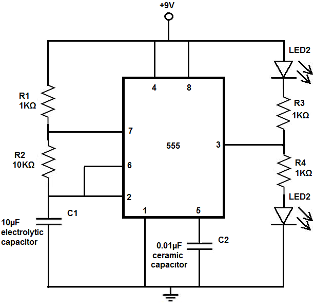
It seems that most of these flashing LED circuits are built with a 555 timer - here's a schematic for an alternating LED flasher that I found on Instructables:


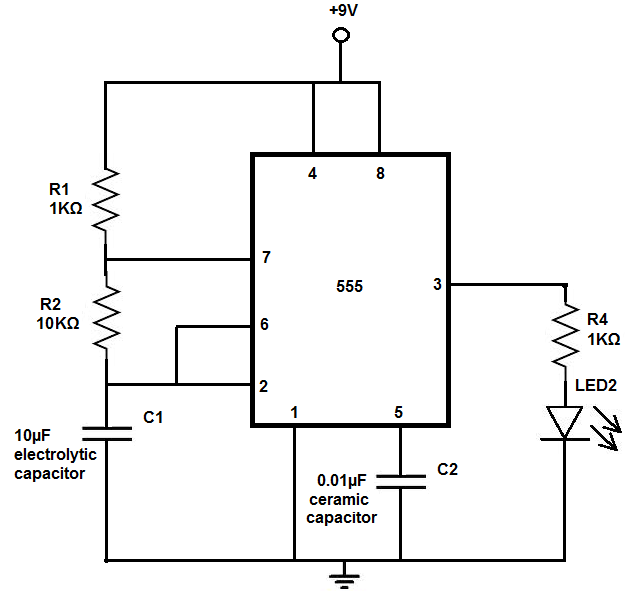
The same Instructables page also gives a circuit for a single flashing LED (which I could probably hook up another LED in parallel to in order to have two simultaneous flashing LEDs):


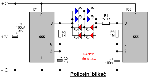
I also found a circuit that strobes the LEDs like police lights:


The problem is combining them all into a single board/circuit, and adding the adjustment for the rate of flashing, as well as making sure the outputs are happy driving LEDs of a fairly wide range of forward voltages. I'm thinking of a few transistors that connect power to the individual function circuits on demand; based on what I've seen, I don't even need to provide a 'go' signal for these, just power.

Is this something I can even do without a MCU?
 

Offline PhoxtaneTopic starter

  • Regular Contributor
  • *
  • Posts: 50
  • Country: us
Re: Flashing Lights Board for Model Vehicles and Signs
« Reply #1 on: July 27, 2016, 07:46:16 pm »
Using some of the free time I have today, I mashed together all three of the circuits I posted above into one schematic:


It probably doesn't work, given that the police strobing circuit requires 12V and the first two circuits run on 9V, and I was hoping to run them on 5V - but if anything, it's a good brain teaser to try to route the PCB for this!

In all seriousness, I'm thinking that doing something like this without a MCU is a really horrible idea... what'd be the best route to approach this, given that the only experience I have with such devices are Arduinos?

And I may have just answered my own question; I can probably use some of the cheap Arduino Nano clones to do this - I'll have to solder on some right-angle headers in order to meet the height restrictions I've imposed on myself, and not power it from the USB.

As for using any color of LED I'd like, I'll just end up putting the resistor in-line with the LED; it should become a 'universal' LED then.
 

Offline ajb

  • Super Contributor
  • ***
  • Posts: 2867
  • Country: us
Re: Flashing Lights Board for Model Vehicles and Signs
« Reply #2 on: July 27, 2016, 08:30:29 pm »
You *could* do this without a micro, but a micro will certainly make for a smaller and more flexible solution.  Compared to four 555s, it may or may not be cheaper.  There are some Arduino-supported boards based on the ATTiny85 that could work nicely, such as the Digispark.  It uses an 8-pin MCU, so after power, Gnd, reset, and the two lines used for USB you've got three uncommitted GPIOs--so enough for two outputs plus a mode button.  Since you'd only need the USB interface for programming (or you can use another Arduino board to program it via the ISP interface), though, you could use those two lines for IO as well and have four outputs plus a mode button.  If you go with an MCU, then you'll want to provide transistors to drive multiple LEDs.

As far as mixing LEDs of different Vf, it's simply a matter of fitting a different series resistor to provide the desired current.  The required current depends on the desired brightness, so this may be a matter of trial and error.
 

Offline Kilrah

  • Supporter
  • ****
  • Posts: 1852
  • Country: ch
Re: Flashing Lights Board for Model Vehicles and Signs
« Reply #3 on: July 27, 2016, 09:50:08 pm »
A network of WS2812s...

Sorry, just got some and they're so fun  ;D
 

Offline PhoxtaneTopic starter

  • Regular Contributor
  • *
  • Posts: 50
  • Country: us
Re: Flashing Lights Board for Model Vehicles and Signs
« Reply #4 on: July 27, 2016, 11:27:27 pm »
As far as mixing LEDs of different Vf, it's simply a matter of fitting a different series resistor to provide the desired current.  The required current depends on the desired brightness, so this may be a matter of trial and error.

Or I can use one of the online calculators to figure out what resistor I need - whatever works, I suppose!

The Digispark is a great idea; is it possible to use it to drive servos as well, using the standard Arduino library? Are there more options beyond the Digispark for a tiny Arduino-IDE compatible MCU board?

A network of WS2812s...

Sorry, just got some and they're so fun  ;D

I'm not doing anything quite that fancy, thankfully - just need lights to come on or off at a certain rate as desired! I also want the 3mm LED form factor so I can squeeze them into Lego models to place around my layout; SMD units won't work so well, especially since I need to fit them up inside bricks and I'd have no good way to get leads attached to them.

EDIT: I did take a quick look around the internet and it would appear that much like Arduino, there's cheap versions of the Digispark out there. Do these have the same issues with the USB-to-serial chips that cheap Arduinos do? I'd love to get my hands on five of these to play around with like I did the Arduinos.
« Last Edit: July 27, 2016, 11:44:23 pm by Phoxtane »
 

Offline ajb

  • Super Contributor
  • ***
  • Posts: 2867
  • Country: us
Re: Flashing Lights Board for Model Vehicles and Signs
« Reply #5 on: July 28, 2016, 12:08:25 pm »
I don't have any specific knowledge of library support for the Digispark, sorry.  The control protocol for hobby servos is ridiculously slow in microcontroller terms, so any MCU out there could do it.

EDIT: I did take a quick look around the internet and it would appear that much like Arduino, there's cheap versions of the Digispark out there. Do these have the same issues with the USB-to-serial chips that cheap Arduinos do? I'd love to get my hands on five of these to play around with like I did the Arduinos.
No, they actually bit-bang the USB interface directly from the MCU.  It's kludgy, but it's cheap and seems to work fine for most people  :-//.
 

Offline PhoxtaneTopic starter

  • Regular Contributor
  • *
  • Posts: 50
  • Country: us
Re: Flashing Lights Board for Model Vehicles and Signs
« Reply #6 on: July 28, 2016, 05:15:09 pm »
I don't have any specific knowledge of library support for the Digispark, sorry.  The control protocol for hobby servos is ridiculously slow in microcontroller terms, so any MCU out there could do it.

...

No, they actually bit-bang the USB interface directly from the MCU.  It's kludgy, but it's cheap and seems to work fine for most people  :-//.

Looking around it seems that whenever people try to use the Digispark for servo control they run into issues due to the lack of hardware PWM pins and the fact that the ATTiny85 is 8-bit only. I think I'll stick to cheap Arduino Nano clones.

On a related note, I tried to desolder the straight pin headers from one of my cheap Nanos last night in order to attach some right-angle headers for a lower profile. That didn't work well at all - not only could I not get the solder out of the vias, I ended up lifting the pads on a few pins. I ended up trashing the board and had some fun with my hot air gun removing all the components. I guess I'll pick up another five-pack without the headers as well as some right-angle headers to solder in place - should be much easier than desoldering, I hope.
 

Offline ajb

  • Super Contributor
  • ***
  • Posts: 2867
  • Country: us
Re: Flashing Lights Board for Model Vehicles and Signs
« Reply #7 on: July 28, 2016, 06:41:39 pm »
I don't have any specific knowledge of library support for the Digispark, sorry.  The control protocol for hobby servos is ridiculously slow in microcontroller terms, so any MCU out there could do it.

...

No, they actually bit-bang the USB interface directly from the MCU.  It's kludgy, but it's cheap and seems to work fine for most people  :-//.

Looking around it seems that whenever people try to use the Digispark for servo control they run into issues due to the lack of hardware PWM pins and the fact that the ATTiny85 is 8-bit only. I think I'll stick to cheap Arduino Nano clones.

Wha?  It's got three hardware PWM pins (well, four, but one is only a complementary channel).  But you don't even need hardware PWM to drive a hobby servo--you've got two hardware timers, that's all you need, you can toggle the IOs in a timer ISR.  Hobby servos are the sort of thing that it's practically counterproductive to use hardware PWM on directly, because your duty cycle only ranges from 5-10%, so only 5% of your possible counter values actually account for your positioning resolution.  That's like 4.5 bits of resolution completely wasted, so unless you have a bunch of spare 16 bit timer channels laying around, it usually makes more sense to use a single timer and an ISR to handle a bunch of different servo channels.  If you stick to the 1/20ms update rate and 1-2ms pulse width, you can control twenty servos from one timer with the full timer resolution available to control position and still have zero chance of the timing between two channels colliding.

Perhaps the Arduino servo library conflicts with the timer requirements of the V-USB implementation on the digispark?  But in that case I don't know why you wouldn't switch it to the other timer when the library is ported.
 

Offline Kilrah

  • Supporter
  • ****
  • Posts: 1852
  • Country: ch
Re: Flashing Lights Board for Model Vehicles and Signs
« Reply #8 on: July 28, 2016, 07:26:42 pm »
it usually makes more sense to use a single timer and an ISR to handle a bunch of different servo channels.
If you do that the more servos you control the more they will jitter, which is why hardware PWM is preferred.
 

Offline PhoxtaneTopic starter

  • Regular Contributor
  • *
  • Posts: 50
  • Country: us
Re: Flashing Lights Board for Model Vehicles and Signs
« Reply #9 on: July 29, 2016, 05:58:45 am »
If you do that the more servos you control the more they will jitter, which is why hardware PWM is preferred.

Given that the application for these servos is going to be in switch control and railroad crossing gates, the less jitter the better. I'd rather not have my crossing gates twitching!
 

Offline ajb

  • Super Contributor
  • ***
  • Posts: 2867
  • Country: us
Re: Flashing Lights Board for Model Vehicles and Signs
« Reply #10 on: July 29, 2016, 11:57:06 am »
it usually makes more sense to use a single timer and an ISR to handle a bunch of different servo channels.
If you do that the more servos you control the more they will jitter, which is why hardware PWM is preferred.

Not if you do it right.   :)  The nominal control pulse for a servo is 1-2ms every 20ms, so every 2ms the micro can focus exclusively on one servo and flip the right IO in an ISR.  Then for the next 2ms, it can focus on the next servo.  That allows you to run ten servos at 50Hz with a single timer, using the full timer resolution for positioning, and as long as your ISR is constructed properly and can always hit its mark there will be no jitter.  Because the first millisecond of the pulse is nominally always high you could interleave pulses without having any timing collisions, and control twenty servos at 50Hz, still with no jitter.

Now whether you can do that on the digispark is another question.  You would certainly run into trouble with timing while using the USB interface, which is one of the big drawbacks of implementing a USB stack in firmware on an 8-bit micro.  I would assume that you can run your application without the USB interface active, though, in which case I see no reason why you couldn't make it work.

I will grant that hardware PWM is easier, but you're going to be limited to the number of hardware channels available.  And FWIW, I seem to recall that the Arduino servo library can use any IO pin, which means it doesn't use hardware PWM (but may use a hardware timer).  Of there are other options involving external hardware...
 

Offline Kilrah

  • Supporter
  • ****
  • Posts: 1852
  • Country: ch
Re: Flashing Lights Board for Model Vehicles and Signs
« Reply #11 on: July 29, 2016, 12:12:44 pm »
Not if you do it right.   :)

Agreed if that's your only interrupt source. If you have others then they'll still occasionally clash.
 

Offline Seekonk

  • Super Contributor
  • ***
  • Posts: 2036
  • Country: us
Re: Flashing Lights Board for Model Vehicles and Signs
« Reply #12 on: July 29, 2016, 06:27:54 pm »
Connectors, we don't need no stinking connectors. I'm all for the nano like things.  Don't even worry about side connectors.  Do what the manufacturers do. Just stick some pins in the hole and angle a little bit sideways.  It will make contact.  Then pull the pins out.  You can't get smaller, have a board and components for less than these $2 micros without USB.  I've done some nice animation effects using the random function like burning buildings.   You could also have flashing lights come on randomly on vehicles. It is probably less than a dozen lines of code. 
 

Offline PhoxtaneTopic starter

  • Regular Contributor
  • *
  • Posts: 50
  • Country: us
Re: Flashing Lights Board for Model Vehicles and Signs
« Reply #13 on: July 30, 2016, 12:17:02 am »
Not if you do it right.   :)  The nominal control pulse for a servo is 1-2ms every 20ms, so every 2ms the micro can focus exclusively on one servo and flip the right IO in an ISR.  Then for the next 2ms, it can focus on the next servo.  That allows you to run ten servos at 50Hz with a single timer, using the full timer resolution for positioning, and as long as your ISR is constructed properly and can always hit its mark there will be no jitter.  Because the first millisecond of the pulse is nominally always high you could interleave pulses without having any timing collisions, and control twenty servos at 50Hz, still with no jitter.

Now whether you can do that on the digispark is another question.  You would certainly run into trouble with timing while using the USB interface, which is one of the big drawbacks of implementing a USB stack in firmware on an 8-bit micro.  I would assume that you can run your application without the USB interface active, though, in which case I see no reason why you couldn't make it work.

I will grant that hardware PWM is easier, but you're going to be limited to the number of hardware channels available.  And FWIW, I seem to recall that the Arduino servo library can use any IO pin, which means it doesn't use hardware PWM (but may use a hardware timer).  Of there are other options involving external hardware...

While I do understand the control scheme these servos use, I'm not familiar with the other components to the solution you're proposing. While I have enjoyed working with Verilog, the last time I tried to do something beyond 'on-off' with an Arduino, I got so frustrated I had to lie down and count to ten, it took a lot of outside help to get it working!

I am thinking it may be a good idea to set up a tiny PCB that will let me separate the servos' power supply from the Arduino control unit - I assume it'll be perfectly happy sending control signals out to multiple servos at a given time, but certainly not powering more than one (maybe not even one under stall conditions). The setup for my layout basically gives me a lot of horizontal space, but not so much vertical space, so I'm perfectly okay with daisy-chaining multiple boards horizontally.

The other option I have is to control the servos from my FPGA master controller - I'd prefer to avoid this, as not only is my I/O very limited (relatively speaking), but that would mean having to build up the servo control protocol in Verilog, and I'm not quite there yet in terms of my skill level. On the other hand, I'd be able to avoid using interrupts entirely and there shouldn't be any jitter, since it'd all be running in parallel.


Share me

Digg  Facebook  SlashDot  Delicious  Technorati  Twitter  Google  Yahoo
Smf