I'm currently working on a frequency counter It's all 4000 series cmos chips and it's coming along nicely.
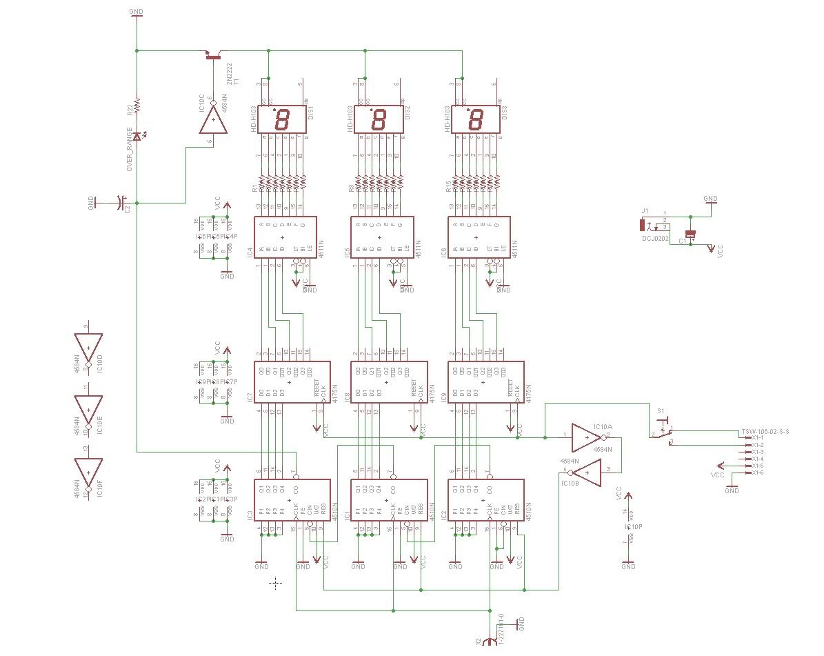
Basically its 3 BCD's (Binary Coded Decimal) counters outputting its value into 3 quad d-latch chips (4175) and then outputting into a binary to 7-segment converter, then to 3 seven segment display's.
THE COUNTThe wave form you are testing feeds the clock pulse for each BCD which in turn counts the frequency.
RANGEThe range is set by a sample wave at 1 hz (or 1 khz depending on what range you want). This will cause the d-latches to latch whatever value the BCD's have once per second. A delay caused by two not gates will give the d-latches time to latch the value before the signal reaches the reset pins of the bcd's reseting the bcd's to zero. and starting the process all over again.
The latches now have the frequency as a BCD value.
DISPLAYThe value stored in the 3 d-latches can then be fed directly to the 3 bin to seven segment decoder and onto the displays.
OVER RANGEIf the carryout bit on the last BCD goes high it means that the frequency counter has gone over range, however this pin will immediately go out as all the BCD's will reset.
In order to indicate to the user that an over range has occurred the carryout bit will charge the capacitor C2 which will keep the signal a logical 1 long enough for another cycle to go through. If the frequency is still over range the carryout signal will refresh the charge in the capacitor. The capacitor is simply used to create a delay.
The signal from the carry out bit will then go through an LED to indicate an over range has occurred. The signal will then go through a not gate then into an NPN transistor which will then disable the display until the over range issue has been corrected.
I'm not exactually sure what I'm going to use for the 1hz clock and the 1khz clock for the range select. So I just have it going to a header right now.
The schematic