Author Topic: Hack to convert from/to 110V to/from 220V main voltage. Basics guide & Examples  (Read 105591 times)

0 Members and 1 Guest are viewing this topic.

Offline ZuccaTopic starter

  • Supporter
  • ****
  • Posts: 4306
  • Country: it
  • EE meid in Itali
Guys,

I know you can buy a 110V<-->220V transformer, but is it not our bench already crowded enough? Is it a good idea to carry a heavy transformer in addition to the device you need? Why not to use the brain instead of money? And what about the max. power limitation? BTW the buzzing noise drives me nuts.

Common mortal people think a main plug adapter like those ones:

will solve all the problems. Well let them believe they can recharge the phone with the WIFI RF energy.

I was always wondering if it is possible to hack a 110V device (sometime it's so cheap tp buy in $, if the shipping/custom cost are reasonable) into a 220V one and vice versa. After a little research I found almost nothing regarding this topic (only sporadic hack guide for some product).

I'm just an EE with a little bit of passion and I travel a lot in the past in different countries so I build up a little experience on this stuff.
Forgive me if this is not 100% correct or need modifications/better technical descriptions. I will try to keep the important information in this first page post.
As Dave says, it´s our forum.

I'm not responsible for any call to the local fire department or burned devices. Triple check everything. It could cost a lot of money or be lethal for you and/or the end user.

WARNING YOU WILL WORK WITH HIGH DANGEROUS MAIN VOLTAGES! USE CAUTION AND THINK TWICE BEFORE ACT!

Worldwide situation

Genreally (99%): 220VAC 50Hz or 110VAC 60Hz

for details

http://en.wikipedia.org/wiki/Mains_electricity_by_country

check also how many main plugs are out there!

Hacking the power lines to get the desired voltage out

It also looks like generally the frequency difference 50/60Hz will not be a big problem.

For 110VAC residential voltage (i.e. US/Canada):

You can get directly the 240VAC for the main power line by tapping off the two opposite phases. Please read before regarding so e safety issues. A transformer is suggested because it is more safe. In addition to that please check if have a dryer or a kitchen oven close where you want the 240V, as I saw those devices runs at 240VAC, so you can just tap the two phases out there... Please consider also the circuit beaker Ampere size since you are now running more than a single device with it.

For 240VAC residential voltage (i.e. Europe):

Here no mercy, you need a transformer. I was starting to investigate the possibility to use a TRIAC to get the wave to max 110VAC (in some 110VAC device it could be a winner), but for business case and complexity doesn't make too much sense.

Hacking the device to work with the current voltage

In this section we will investigate the possibility to get the device running with a different main power supply voltage

The golden label rule

First look at the label of your product, it should tell you right away if you need a hack or not.
If this is impossible to look at it don't risk, trust the main plug (and/or main fuse) to determine which is the main voltage and consider this device as not worldwide compatible.

Circuit classification

I would start by dividing the devices in three big groups. It's a very difficult task but it cleans up the air a little bit (I hope).

a) DC operating circuits (99% <100W range)

Usually powered by rechargeable batteries this kind of circuits are 99% already compatible with all the world.
Example of this are infinite: 99% of the battery charger units (for laptop, phones, etc) but also table LED table lamp.
Here it is common to have a separated power unit from the devices which take care about the main AC to DC conversion (yes the ones which never fit in the laptop case).
Interesting enough if the final device need manly just DC (i.e. oscilloscope or computer) it is a very good sign you don't need any hack at all.
The need to hack/mod a circuit here is a sporadic event, and it is manly an easy job: find/design and replace the correct AC/DC converter (inside or outside the product case).

b) DC Small/medium power circuits (99% 100W-1000W range)

Here it depends. Manly politic business case are the driver to get a device compatible worldwide or not. Power drill charger or UPS unit for computers are a good example of it.
Also devices which uses electricity to produce a lot of heat (hot air guns, ovens, etc.) are most of all not worldwide. I think it is related to the heater resistor which need a circuit close to the main voltage.

Here an hack can save money (especially for used stuff from ebay), but it would need reverse engineering and the possibility to get access and modify the power circuit.

c) Power device (99% >1000W)

Devices which use components powered in AC (electric motors, heater resistors) or big main voltage transformer are almost impossible to hack or the business case is red.
An hack would involve to replace costly components, just open the case and cry on it. If you are a Braveheart of hacking keep a fire extinguisher close to you, or expect the unexpected.

Basic "How to" guide

If there is a main switch (110VAC/220AV, usually on the back panel close to the AC main input) you are done, just adjust the main plug (mandatory!) and check if the main fuse needs to be replaced. The fuse could be in the AC main input connector, see below:

or inside your device.

In case of no main switch or a not world wide compatible product, at this point you should consider to attempt a main circuit modification to your device.

As mikeselectricstuff would say there is no guide to reverse engineering. I try to give some suggestions, forgive me my experience is not huge.

- Google it, 99% you are not the first to face this problem. Sometimes there is even a kit to convert the main power device, see example here thanks to nowlan
wooh.
Just notice someone selling a bosch 10.8v charger conversion kit on ebay.
link

I got scared off when i noticed all the caps were 110v rated on my US charger.


- Make sure the main capacitors are fully discharged, they can be dangerous and hold the charge for days. Thanks to Legit-Design, please see details in this post:
https://www.eevblog.com/forum/chat/need-a-russian-speacker-to-translate-a-you-tube-hack-video/msg376102/#msg376102

- Follow the main lines like Alice did with the white rabbit. Thanks to vk6zgo check the fuse in the power lines (they could be on both lines) and the RF filter capacitor. See post here:
https://www.eevblog.com/forum/projects/hack-to-convert-fromto-110v-tofrom-220v-main-voltage-basics-guide-examples/msg375549/#msg375549

...and check if all the components (all, everything connected to main, protection components included) are capable of the target voltages. Normally a 220V device will not work (well) in a 110V network. Be ready to call the firefighters in case you are trying to power up a 110V device with a 220V.

- Try to understand where the voltage is converted to a different nature (AC/DC) or amplitude, in other words try to isolate the power circuit from the rest of the circuit. The modifications should be related only to the power circuit, so you can 99% ignore the rest.

- get or reverse engineer the schematics of the main power board

- Does a different main frequency (50/60 Hz) play a role? Don´t forget this topic.

- Does the product have radio communication? Check if you can use that frequency in the target country (i.e. I heard in China the 125KHz is used for military purpose). Don´t forget this topic.

- Try to disconnect the power circuit from the rest and keep this last one disconnected and safe. It is better to risk just on the main power circuit.

- If it is impossible to disconnect the power circuit from the rest  try to keep safe crucial components (and the ones difficult to replace) by disconnection or desoldering costly chips, if you can without damaging anything). It will cost time but can save money and the entire project success.

- use a lot of brain and do not try before to post your problems in this forum.

- Hack it. Nice to have try to design the mod as a worldwide compatible, it could be handy for a lot of people out there.

- after the hack, measure and check the power supply voltages (if you are using an oscilloscope be careful you can't connect the probes directly to the main voltages or go on too high voltages)

- rebuild it together and pray.

- Success? post it in the forum.

Examples

Computer PSU

here is interesting to see how a 110V/220V switch works, just for your inspiration
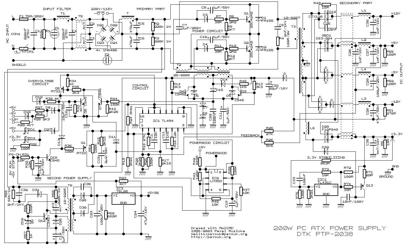

details here:
http://www.pavouk.org/hw/en_atxps.html

Makita DC18RA Mod

From 110V to 220V:

http://www.schneordesign.com/Avi/Makita/makita_mod1.htm

Makita DC10WB Mod

From 110V to 220V:


Thanks to Legit-Design, please see details in this post:

https://www.eevblog.com/forum/chat/need-a-russian-speacker-to-translate-a-you-tube-hack-video/msg376102/#msg376102

it has russian subtitles AND he shows how to hack it. AND youtube can translate the russian subtitles to english.

Even if I didn't know russian and this didn't have any subtitles it would be relatively easy to do the hack.

Basically change resistor to match your input voltage, the charger already has this built in because they change few components for different markets. Change capacitors to match 400V which is typical for 230V operated switch mode power supplies, check to see if protection components can withstand the higher voltage. You could probably take old working computer power supply apart and get the necessary parts from there.

Z

PS: I live in US but I have 220V, 60Hz(!) lines under my bench to power up my european equipment, it was just a wire from the main electric power of my apartment. Yes I hate big transformer.

 
« Last Edit: January 27, 2014, 08:20:40 pm by zucca »
Can't know what you don't love. St. Augustine
Can't love what you don't know. Zucca
 

Online Psi

  • Super Contributor
  • ***
  • Posts: 9924
  • Country: nz
Good old TL494 :)
Greek letter 'Psi' (not Pounds per Square Inch)
 

Offline NiHaoMike

  • Super Contributor
  • ***
  • Posts: 9004
  • Country: us
  • "Don't turn it on - Take it apart!"
    • Facebook Page
For the case of converting a 240V input switching power supply to 120V, easiest solution is a voltage doubler.
Cryptocurrency has taught me to love math and at the same time be baffled by it.

Cryptocurrency lesson 0: Altcoins and Bitcoin are not the same thing.
 

Offline nickm

  • Regular Contributor
  • *
  • Posts: 79
Here's the redneck way.  There's already 240V in your house so what you do is get and extension cord and a multimeter.  Pick an outlet in the room you are using.  Plug the extension cord into an outlet in another room.  Measure the voltage from hot to hot of the extension cord and the outlet.  If you get 0Vac move the extension cord to another outlet.  If you get 120Vac you are measuring hot to neutral and are doing it wrong.  If you get 240Vac you are good because you have found an outlet on the other phase.  Make a box that takes in 2 IEC cables and outputs to a single 240Vac plug.  Connect each of the hots from the IEC connectors to one side of the 240Vac plug.  Plug the box into the outlet and the extension cord.  You now have a 240Vac outlet. 
 

Offline temmi_hoo

  • Contributor
  • Posts: 28
  • Country: fi
  • ELL-i PoE grassroots DC revolution
    • ELL-i -- Open Source PoE Intelligence -- Home
Here's the redneck way.  There's already 240V in your house so what you do is get and extension cord and a multimeter.  Pick an outlet in the room you are using.  Plug the extension cord into an outlet in another room.  Measure the voltage from hot to hot of the extension cord and the outlet.  If you get 0Vac move the extension cord to another outlet.  If you get 120Vac you are measuring hot to neutral and are doing it wrong.  If you get 240Vac you are good because you have found an outlet on the other phase.  Make a box that takes in 2 IEC cables and outputs to a single 240Vac plug.  Connect each of the hots from the IEC connectors to one side of the 240Vac plug.  Plug the box into the outlet and the extension cord.  You now have a 240Vac outlet.

This could be made a device with two input cables and one outlet. It would have a meter or some indicator lights indicating is a plug needs reversing. I think it would not be ultrahard to automate this but I'd still want those indicators and possibly a nice needle meter.

Mostly I don't see a problem as modern low and medium power devices already have an universal power supply accepting anything between 90 and 260VAC in either 50/60Hz form. Thusly I don't think it would sell a lot but be a cool hacker project to brag about at the hackerspace you're visiting.

Also, if you use it in Europe you'll end up with 400VAC that'll fry stuff faster, except in Norway, who use electricity always from between phases and mostly don't do anything with the star point.
 

Offline ZuccaTopic starter

  • Supporter
  • ****
  • Posts: 4306
  • Country: it
  • EE meid in Itali
For the case of converting a 240V input switching power supply to 120V, easiest solution is a voltage doubler.

I think the PSU circuit I posted does exactly that...
Can't know what you don't love. St. Augustine
Can't love what you don't know. Zucca
 

Offline calzap

  • Frequent Contributor
  • **
  • Posts: 448
  • Country: us
Here's the redneck way.  There's already 240V in your house so what you do is get and extension cord and a multimeter.  Pick an outlet in the room you are using.  Plug the extension cord into an outlet in another room.  Measure the voltage from hot to hot of the extension cord and the outlet.  If you get 0Vac move the extension cord to another outlet.  If you get 120Vac you are measuring hot to neutral and are doing it wrong.  If you get 240Vac you are good because you have found an outlet on the other phase.  Make a box that takes in 2 IEC cables and outputs to a single 240Vac plug.  Connect each of the hots from the IEC connectors to one side of the 240Vac plug.  Plug the box into the outlet and the extension cord.  You now have a 240Vac outlet.

Yikes!  Very unsafe device!  What happens if you put the plugs into a pair of 120 VAC outlets served by the same phase but by different breakers?  Well, the outlet on the box has just had its over-current protection doubled.  If the 120 VAC outlets were protected by 15 A breakers, the outlet on the box now has 30 A of protection.  Fire and shocks may occur.  Even if the plugs are connected to opposite phases, there is potential (no pun) danger.  There is a reason the handles of the two sub-breakers that make-up a 240 VAC breaker are tied together.  It's so the whole 240 VAC circuit becomes dead if either phase gets shorted or grounded.

Mike in California
 

Offline don.r

  • Frequent Contributor
  • **
  • Posts: 740
  • Country: ca
Its not called Redneck for nothin'.

I have a 1000VA autotransformer under the bench creating 240V/60Hz and a UK plug strip on the bench. The nice things about autotransformers is they have multiple taps so I can use it to get 55V as well if I need to power on an unknown device of dubious origin. Both ground and neutral connect straight through to the 120V house wiring. The unit has its own breaker. Safe, simple, out of sight.
 

Offline NiHaoMike

  • Super Contributor
  • ***
  • Posts: 9004
  • Country: us
  • "Don't turn it on - Take it apart!"
    • Facebook Page
Here's the redneck way.  There's already 240V in your house so what you do is get and extension cord and a multimeter.  Pick an outlet in the room you are using.  Plug the extension cord into an outlet in another room.  Measure the voltage from hot to hot of the extension cord and the outlet.  If you get 0Vac move the extension cord to another outlet.  If you get 120Vac you are measuring hot to neutral and are doing it wrong.  If you get 240Vac you are good because you have found an outlet on the other phase.  Make a box that takes in 2 IEC cables and outputs to a single 240Vac plug.  Connect each of the hots from the IEC connectors to one side of the 240Vac plug.  Plug the box into the outlet and the extension cord.  You now have a 240Vac outlet.

Yikes!  Very unsafe device!  What happens if you put the plugs into a pair of 120 VAC outlets served by the same phase but by different breakers?  Well, the outlet on the box has just had its over-current protection doubled.  If the 120 VAC outlets were protected by 15 A breakers, the outlet on the box now has 30 A of protection.  Fire and shocks may occur.  Even if the plugs are connected to opposite phases, there is potential (no pun) danger.  There is a reason the handles of the two sub-breakers that make-up a 240 VAC breaker are tied together.  It's so the whole 240 VAC circuit becomes dead if either phase gets shorted or grounded.

Mike in California

There's a commercial product that does just that, but it has quite a few interlocks for safety. It's apparently popular with EV owners who want to charge twice as fast.
http://www.quick220.com/-A220-20D.html
Cryptocurrency has taught me to love math and at the same time be baffled by it.

Cryptocurrency lesson 0: Altcoins and Bitcoin are not the same thing.
 

Offline calzap

  • Frequent Contributor
  • **
  • Posts: 448
  • Country: us

[/quote]
There's a commercial product that does just that, but it has quite a few interlocks for safety. It's apparently popular with EV owners who want to charge twice as fast.
http://www.quick220.com/-A220-20D.html
[/quote]

Yup, and the product addresses both of my concerns.  If the plugs aren't into opposite phases, there is no power at any of the output sockets, and  ditto if only one of the input cords has power.  This device is the way to go if you want to use this technique.

Mike in California
 

Offline Monkeh

  • Super Contributor
  • ***
  • Posts: 7992
  • Country: gb
For what that thing costs, I'd put the effort into running a 240V circuit..
 

Offline NiHaoMike

  • Super Contributor
  • ***
  • Posts: 9004
  • Country: us
  • "Don't turn it on - Take it apart!"
    • Facebook Page
Apparently, it's possible to replicate it with two small 120V coil relays and a large 240V coil relay or contactor. Should be well under $50 for all the parts.

Here's the initial idea, but with just 2 relays: http://www.mynissanleaf.com/viewtopic.php?p=102463
It doesn't actively protect against the case of plugging it into two circuits of the same phase, but it wouldn't work and it's highly unlikely anyone would leave it like that. Adding a third relay can actively protect against that.
Cryptocurrency has taught me to love math and at the same time be baffled by it.

Cryptocurrency lesson 0: Altcoins and Bitcoin are not the same thing.
 

Offline ZuccaTopic starter

  • Supporter
  • ****
  • Posts: 4306
  • Country: it
  • EE meid in Itali
Its not called Redneck for nothin'.

I have a 1000VA autotransformer under the bench creating 240V/60Hz and a UK plug strip on the bench. The nice things about autotransformers is they have multiple taps so I can use it to get 55V as well if I need to power on an unknown device of dubious origin. Both ground and neutral connect straight through to the 120V house wiring. The unit has its own breaker. Safe, simple, out of sight.

Is there also a galvanic main isolation between input and output voltage? I measure my transformer apart and I sadly discover there are no primary or secondary coil it is just one with different tabs.
« Last Edit: January 19, 2014, 10:45:27 pm by zucca »
Can't know what you don't love. St. Augustine
Can't love what you don't know. Zucca
 

Offline don.r

  • Frequent Contributor
  • **
  • Posts: 740
  • Country: ca
Sadly, no. Its just an autotransformer.  I have a 300W isolation transformer that is 2:1 as well though. I really need to get myself a 1:1 isolator.
 

Offline ZuccaTopic starter

  • Supporter
  • ****
  • Posts: 4306
  • Country: it
  • EE meid in Itali
When I modify my apartment power lines I put at the and a 15A thermal-switch for overload and a 10mA differential switch at the end of the 220VAC opposite phases.

Minimal safety should be always there.
Can't know what you don't love. St. Augustine
Can't love what you don't know. Zucca
 

Offline ZuccaTopic starter

  • Supporter
  • ****
  • Posts: 4306
  • Country: it
  • EE meid in Itali
I really need to get myself a 1:1 isolator.

You got me, same situation here. If you find something cheap and good let me know.
Can't know what you don't love. St. Augustine
Can't love what you don't know. Zucca
 

Offline ZuccaTopic starter

  • Supporter
  • ****
  • Posts: 4306
  • Country: it
  • EE meid in Itali
Ops, I think the conversation is going in the direction to modify the wall power line in order to get the the desired voltage out. My initial intention was to focus on the device mod in order to get it compatible with different main voltages. Oh well, not a big deal I can make two big sections in the first post.

I would summarize the main power line modification like this:

For 110VAC residential voltage (i.e. US/Canada):

You can get directly the 240VAC for the main power line by tapping off the two opposite phases. Please read before regarding so e safety issues. A transformer is suggested because it is more safe.
In addition to that please check if have a dryer or a kitchen oven close where you want the 240V, as I saw those devices runs at 240VAC, so you can just tap the two phases out there... Please consider also the circuit beaker Ampere size since you are now running more than a single device with it.

For 240VAC residential voltage (i.e. Europe):

Here no mercy, you need a transformer. I was starting to investigate the possibility to use a TRIAC to get the wave to max 110VAC (in some 110VAC device it could be a winner), but for business case and complexity doesn't make too much sense.

It also looks like generally the frequency difference 50/60Hz will not be a big problem.

Thanks for all your responses!

« Last Edit: January 19, 2014, 11:19:22 pm by zucca »
Can't know what you don't love. St. Augustine
Can't love what you don't know. Zucca
 

Offline ZuccaTopic starter

  • Supporter
  • ****
  • Posts: 4306
  • Country: it
  • EE meid in Itali
... in Norway, who use electricity always from between phases and mostly don't do anything with the star point.

Why? What are the advantages of that?
Can't know what you don't love. St. Augustine
Can't love what you don't know. Zucca
 

Offline temmi_hoo

  • Contributor
  • Posts: 28
  • Country: fi
  • ELL-i PoE grassroots DC revolution
    • ELL-i -- Open Source PoE Intelligence -- Home
... in Norway, who use electricity always from between phases and mostly don't do anything with the star point.

Why? What are the advantages of that?

That way they can still carry the whole three phase system with just three wires as the rest of us. Most of Norway sits on the big slab of rock called Europe and the ground conductance is really super poor. If they did want star system, they'd have to carry the middle conductor as well. Then they'd have the problem of locally grounding it, as it's supposed to be a neutral terminal free from potential.

Now,  if it were up to just me, we'd all be running either DC with suitable voltage or three phase Norway-style with addition of locally grounded safety ground where applicable. I prefer DC for many reasons.
 

Offline Monkeh

  • Super Contributor
  • ***
  • Posts: 7992
  • Country: gb
If they did want star system, they'd have to carry the middle conductor as well.

The way everyone else does?

Quote
Then they'd have the problem of locally grounding it, as it's supposed to be a neutral terminal free from potential.

It's a live conductor like the other three. It's impossible for it to not have a potential.
 

Offline denelec

  • Regular Contributor
  • *
  • Posts: 168
  • Country: ca
If they did want star system, they'd have to carry the middle conductor as well.

The way everyone else does?

Quote
Then they'd have the problem of locally grounding it, as it's supposed to be a neutral terminal free from potential.

It's a live conductor like the other three. It's impossible for it to not have a potential.

In a star multi-grounded distribution system, the earth to neutral voltage should be as low as possible.  Usually below 5V.  Higher voltage can cause problems, especially to dairy farmers. But you can't expect to have exactly 0V.
 

Offline Monkeh

  • Super Contributor
  • ***
  • Posts: 7992
  • Country: gb
In a star multi-grounded distribution system, the earth to neutral voltage should be as low as possible.  Usually below 5V.  Higher voltage can cause problems, especially to dairy farmers. But you can't expect to have exactly 0V.

I know this. The reality of the system is that it is a live conductor.
 

Online vk6zgo

  • Super Contributor
  • ***
  • Posts: 7584
  • Country: au
Ops, I think the conversation is going in the direction to modify the wall power line in order to get the the desired voltage out. My initial intention was to focus on the device mod in order to get it compatible with different main voltages. Oh well, not a big deal I can make two big sections in the first post.

I would summarize the main power line modification like this:

For 110VAC residential voltage (i.e. US/Canada):

You can get directly the 240VAC for the main power line by tapping off the two opposite phases. Please read before regarding so e safety issues. A transformer is suggested because it is more safe.
In addition to that please check if have a dryer or a kitchen oven close where you want the 240V, as I saw those devices runs at 240VAC, so you can just tap the two phases out there... Please consider also the circuit beaker Ampere size since you are now running more than a single device with it.

For 240VAC residential voltage (i.e. Europe):

Here no mercy, you need a transformer. I was starting to investigate the possibility to use a TRIAC to get the wave to max 110VAC (in some 110VAC device it could be a winner), but for business case and complexity doesn't make too much sense.

It also looks like generally the frequency difference 50/60Hz will not be a big problem.

Thanks for all your responses!

In the USA & Canada,you can get a 240v supply wired,which uses the two 120v "antiphase" voltages from the pole transformer,with the centre tap Earthed.
As in a previous suggestion,both ends of the transformer are probably already used to feed different circuits.

Hams often use such outlets to power 1.5kW Linear amplifiers--the Electrician will fit them,you don't have to make up "bodgie " connections.

Quite a lot of TV monitors & the like from NA are wired for this voltage,& have a fuse in both sides of the 240V incoming--which is technically speaking,illegal in Australia.

One thing to watch is where RF filter capacitors are connected between both sides & Earth inside the device.
They may be only rated for 120v service,whereas in Oz,one cap with have zero volts across it,& the other,240v.

You will also need to check these RF filer caps if you are thinking about "hacking" a 120V SMPS.

« Last Edit: January 26, 2014, 03:12:07 am by vk6zgo »
 

Offline temmi_hoo

  • Contributor
  • Posts: 28
  • Country: fi
  • ELL-i PoE grassroots DC revolution
    • ELL-i -- Open Source PoE Intelligence -- Home
In a star multi-grounded distribution system, the earth to neutral voltage should be as low as possible.  Usually below 5V.  Higher voltage can cause problems, especially to dairy farmers. But you can't expect to have exactly 0V.

I know this. The reality of the system is that it is a live conductor.

It most definitely is a current-carrying conductor and I should have stated that its potential should be near zero. Anyway the Norwegians have their normal 1 phase outlets wired between phases, the main voltage being 240V. Nothing gets connected between a phase and neutral.

Regarding how and what wires are carried, the high voltage and medium voltage trunk lines carry just three phases. Then the low voltage (that you have in the sockets) side carries four conductors in star configuration. The neutral is grounded at the transformer station and also at the house connection point. Now, if the local earth is very poorly conductive this scheme doesn't work very well in case of distribution network cable failure.

Personally I dislike the PEN conductor and would much prefer that my protective earth would not be connected to distribution network, as partial cable failures may make my supposedly safe zero potential terminals, computer cases and water pipes etc hang at some arbitary potential depending on how the local star point settles.

I do live in the countryside with pole hanging distribution network, where zero conductor failures occur just as frequently as any other partial network failures and this is a real safety threat.
 

Online Zero999

  • Super Contributor
  • ***
  • Posts: 19479
  • Country: gb
  • 0999
I really need to get myself a 1:1 isolator.

You got me, same situation here. If you find something cheap and good let me know.
RS Components sell them.
Twin 115V primary and twin 115 secondary.
http://uk.rs-online.com/web/p/toroidal-transformers/7529242/


Share me

Digg  Facebook  SlashDot  Delicious  Technorati  Twitter  Google  Yahoo
Smf