Author Topic: Impedance Analyzer Build and Experiments  (Read 110371 times)

0 Members and 1 Guest are viewing this topic.

Offline jaxbirdTopic starter

  • Frequent Contributor
  • **
  • Posts: 778
  • Country: 00
Re: Impedance Analyzer Build and Experiments
« Reply #25 on: June 26, 2014, 08:52:33 pm »
Not really related, but I do find it odd the way TI decided to market the BUF634:

Among their main use cases are motor and Solenoid driver. I cannot think of a case where anyone would need a 150MHz bandwidth and 2000V/us slew rate buffer to drive a motor or a solenoid  :P

Surely a much cheaper solution would do just fine for those applications.

But as a generic opamp booster it's very potent.

Analog Discovery Projects: http://www.thestuffmade.com
Youtube random project videos: https://www.youtube.com/user/TheStuffMade
 

Offline dannyf

  • Super Contributor
  • ***
  • Posts: 8221
  • Country: 00
Re: Impedance Analyzer Build and Experiments
« Reply #26 on: June 26, 2014, 10:12:01 pm »
Quote
But as a generic opamp booster it's very potent.

More so as a hi-fi headphone driver.
================================
https://dannyelectronics.wordpress.com/
 

Offline Zad

  • Super Contributor
  • ***
  • Posts: 1013
  • Country: gb
    • Digital Wizardry, Analogue Alchemy, Software Sorcery
Re: Impedance Analyzer Build and Experiments
« Reply #27 on: June 27, 2014, 03:08:49 am »
In the AD app notes they suggest using an AD8606 which has 1 Ohm output impedance. See their circuit Lab reference CN-0217. As a suggestion, try taking the feedback for the drive amplifier from the DUT side of the drive current limiting resistor.


Offline theatrus

  • Frequent Contributor
  • **
  • Posts: 352
  • Country: us
Re: Impedance Analyzer Build and Experiments
« Reply #28 on: June 27, 2014, 06:42:14 am »
There is also the LME49600 opamp buffers from National (TI). They're intended for audio use as well but have similar redonkulous slew rates.
Software by day, hardware by night; blueAcro.com
 

Offline jaxbirdTopic starter

  • Frequent Contributor
  • **
  • Posts: 778
  • Country: 00
Re: Impedance Analyzer Build and Experiments
« Reply #29 on: June 27, 2014, 08:25:06 am »
In the AD app notes they suggest using an AD8606 which has 1 Ohm output impedance. See their circuit Lab reference CN-0217. As a suggestion, try taking the feedback for the drive amplifier from the DUT side of the drive current limiting resistor.

Thanks, that's good advise, I must have missed that application note. In the main datasheet they only suggest AD8531,
AD820, AD8641 and AD8627. Of which AD8531 looked the best.

I'll try get my hands on a few AD8606.

In the meantime I'll try out this configuration:


I will also need to do some level shifting.
Analog Discovery Projects: http://www.thestuffmade.com
Youtube random project videos: https://www.youtube.com/user/TheStuffMade
 

Offline jaxbirdTopic starter

  • Frequent Contributor
  • **
  • Posts: 778
  • Country: 00
Re: Impedance Analyzer Build and Experiments
« Reply #30 on: June 29, 2014, 11:41:37 pm »
More so as a hi-fi headphone driver.

Yeah, that was probably the purpose I had in mind when I bought the BUF634.

There is also the LME49600 opamp buffers from National (TI). They're intended for audio use as well but have similar redonkulous slew rates.

Very similar specs, and cheaper  :-+ good suggestion.

Analog Discovery Projects: http://www.thestuffmade.com
Youtube random project videos: https://www.youtube.com/user/TheStuffMade
 

Offline jaxbirdTopic starter

  • Frequent Contributor
  • **
  • Posts: 778
  • Country: 00
Re: Impedance Analyzer Build and Experiments
« Reply #31 on: June 29, 2014, 11:48:13 pm »
Got the large breadboard out to build up a Buf634 based circuit with associated components:


It's a good improvement in performance:


But it's not a good idea to attempt accurate low impedance measurements using a breadboard circuit where each connection point got something like a 50 milliohm+ resistance  :o

Next I'll make a PCB for more accurate evaluation.

Analog Discovery Projects: http://www.thestuffmade.com
Youtube random project videos: https://www.youtube.com/user/TheStuffMade
 

Offline dannyf

  • Super Contributor
  • ***
  • Posts: 8221
  • Country: 00
Re: Impedance Analyzer Build and Experiments
« Reply #32 on: June 30, 2014, 12:22:43 am »
Quote
using a breadboard circuit where each connection point got something like a 50 milliohm+ resistance

Depending on the math utilized. You can, for example, decompose the amplitude + phase angle into real + imaginary parts and null the impact of the wires if you perform two measurements at each frequency. The resulting real + imaginary parts can be re-converted back to amplitude + phase angle of the DUT.
================================
https://dannyelectronics.wordpress.com/
 

Offline Odysseus

  • Regular Contributor
  • *
  • Posts: 147
  • Country: us
Re: Impedance Analyzer Build and Experiments
« Reply #33 on: June 30, 2014, 07:24:31 am »
Quote
using a breadboard circuit where each connection point got something like a 50 milliohm+ resistance

Depending on the math utilized. You can, for example, decompose the amplitude + phase angle into real + imaginary parts and null the impact of the wires if you perform two measurements at each frequency. The resulting real + imaginary parts can be re-converted back to amplitude + phase angle of the DUT.

Another option is to use a kelvin (4 wire) connection to the DUT.  Kind of a must at low impedances.
« Last Edit: June 30, 2014, 07:26:47 am by Odysseus »
 

Offline jaxbirdTopic starter

  • Frequent Contributor
  • **
  • Posts: 778
  • Country: 00
Re: Impedance Analyzer Build and Experiments
« Reply #34 on: June 30, 2014, 08:36:28 am »
Quote
using a breadboard circuit where each connection point got something like a 50 milliohm+ resistance

Depending on the math utilized. You can, for example, decompose the amplitude + phase angle into real + imaginary parts and null the impact of the wires if you perform two measurements at each frequency. The resulting real + imaginary parts can be re-converted back to amplitude + phase angle of the DUT.

Probably could, but with breadboard, you just poke a wire or component and the resistance changes :)

My current calibration/compensation is fairly basic, it will be more involved to get full calibration as the frequency response changes slightly with different ohm loads.

I haven't thought of doing the calibration with the real and imaginary numbers, currently I use the magnitude and phase. I'll try have a go with that method once I get the PCB together. I wouldn't even need to decompose as I have the complex real and imaginary available directly from the DFT.

Analog Discovery Projects: http://www.thestuffmade.com
Youtube random project videos: https://www.youtube.com/user/TheStuffMade
 

Offline jaxbirdTopic starter

  • Frequent Contributor
  • **
  • Posts: 778
  • Country: 00
Re: Impedance Analyzer Build and Experiments
« Reply #35 on: June 30, 2014, 08:42:16 am »
Quick proto PCB:


Single sided, not ideal, but many times better than breadboard :)

Just need to get it soldered together and hope I haven't made too many mistakes.


Analog Discovery Projects: http://www.thestuffmade.com
Youtube random project videos: https://www.youtube.com/user/TheStuffMade
 

Offline jaxbirdTopic starter

  • Frequent Contributor
  • **
  • Posts: 778
  • Country: 00
Re: Impedance Analyzer Build and Experiments
« Reply #36 on: June 30, 2014, 08:48:39 am »
Another option is to use a kelvin (4 wire) connection to the DUT.  Kind of a must at low impedances.

Yeah, Kelvin connections would be ideal, but I think I'll try get away with really short wires for now, as it will at best only resolve down into the lower portion of the milliohm range.

Analog Discovery Projects: http://www.thestuffmade.com
Youtube random project videos: https://www.youtube.com/user/TheStuffMade
 

Offline jaxbirdTopic starter

  • Frequent Contributor
  • **
  • Posts: 778
  • Country: 00
Re: Impedance Analyzer Build and Experiments
« Reply #37 on: June 30, 2014, 12:58:59 pm »
A bit old school looking :)


Might have gone a bit overboard with the decoupling.

Analog Discovery Projects: http://www.thestuffmade.com
Youtube random project videos: https://www.youtube.com/user/TheStuffMade
 

Offline dannyf

  • Super Contributor
  • ***
  • Posts: 8221
  • Country: 00
Re: Impedance Analyzer Build and Experiments
« Reply #38 on: June 30, 2014, 01:03:14 pm »
Nicely done.
================================
https://dannyelectronics.wordpress.com/
 

Offline jaxbirdTopic starter

  • Frequent Contributor
  • **
  • Posts: 778
  • Country: 00
Re: Impedance Analyzer Build and Experiments
« Reply #39 on: June 30, 2014, 02:07:27 pm »
Nicely done.

Thanks, it does provide much cleaner (and hopefully more accurate) results:


Note: the degree markers are not placed correctly.

Analog Discovery Projects: http://www.thestuffmade.com
Youtube random project videos: https://www.youtube.com/user/TheStuffMade
 

Offline Zad

  • Super Contributor
  • ***
  • Posts: 1013
  • Country: gb
    • Digital Wizardry, Analogue Alchemy, Software Sorcery
Re: Impedance Analyzer Build and Experiments
« Reply #40 on: July 01, 2014, 01:28:05 am »
Boards fabricated during development often do look oldschool! What matters is that you can get into them to measure and scope signals, and add/remove/swap components as needed. Unless you are working >GHz then track distances and compact boards aren't massively important. I'd be more than happy working with a board like that. If you do another one, maybe bring out the test probe connections to the edge, so the wires aren't trailing over the board?


Offline jaxbirdTopic starter

  • Frequent Contributor
  • **
  • Posts: 778
  • Country: 00
Re: Impedance Analyzer Build and Experiments
« Reply #41 on: July 02, 2014, 03:38:47 am »
Boards fabricated during development often do look oldschool! What matters is that you can get into them to measure and scope signals, and add/remove/swap components as needed. Unless you are working >GHz then track distances and compact boards aren't massively important. I'd be more than happy working with a board like that. If you do another one, maybe bring out the test probe connections to the edge, so the wires aren't trailing over the board?

I think you misunderstood my old school statement, it's not meant that old school isn't perfectly fine in most cases. It's more that well, it does look old school :) Probably 90% of the boards I make are old school, much easier to solder together without soldermask than smd, and much easier to bodge, swap components etc.

I do all my prototype and one off boards on CNC and I can do fine details down to 0.5mm pitch/10 mil tracks, but it can be time consuming and tricky to solder without mask and you don't want to rework a board like that too much. I try to stick with through hole unless it's e.g. a switchmode or something like this CPLD board where everything except the connectors is surface mount:


Analog Discovery Projects: http://www.thestuffmade.com
Youtube random project videos: https://www.youtube.com/user/TheStuffMade
 

Offline jaxbirdTopic starter

  • Frequent Contributor
  • **
  • Posts: 778
  • Country: 00
Re: Impedance Analyzer Build and Experiments
« Reply #42 on: July 02, 2014, 03:48:38 pm »
One of the limitations of the AD5933 is that the ADC sample rate for the DFT depends on the clock, so to capture a full wave for the DFT below ~10kHz an external clock is needed. The optimal is to capture just a single wave in the 1024 points sampled by the ADC. So it does require some slightly complex clock control.

Here a capture with the range down to 100Hz:


It is very slow doing the DFT at the low range though, not sure if the internal DSP runs off the same clock as the ADC.

Analog Discovery Projects: http://www.thestuffmade.com
Youtube random project videos: https://www.youtube.com/user/TheStuffMade
 

Offline jaxbirdTopic starter

  • Frequent Contributor
  • **
  • Posts: 778
  • Country: 00
Re: Impedance Analyzer Build and Experiments
« Reply #43 on: July 04, 2014, 10:55:46 am »
Current setup, getting a bit large:


It works pretty well, but I've been investigating some noise issues.

First major noise source was the CPLD, I had the outputs in fast mode :P added a some better decoupling and changed to slow mode plus a small resistor on the output.

But still some significant noise present:


Turns out it's from the USB/UART converter, probably primarily from the USB data lines:


So I'll need to build a small isolation board with some optocouplers next and hope that gets rid of most of it.

Analog Discovery Projects: http://www.thestuffmade.com
Youtube random project videos: https://www.youtube.com/user/TheStuffMade
 

Offline jaxbirdTopic starter

  • Frequent Contributor
  • **
  • Posts: 778
  • Country: 00
Re: Impedance Analyzer Build and Experiments
« Reply #44 on: July 04, 2014, 12:04:01 pm »
After a bit more probing around, it's not the USB/UART, that was just from bad probing  :P

It appears to be when I use the external clock, here with internal clock (all measured directly on the AD5933, on input between SGND and feedback using very short ground connection, the output is clean)


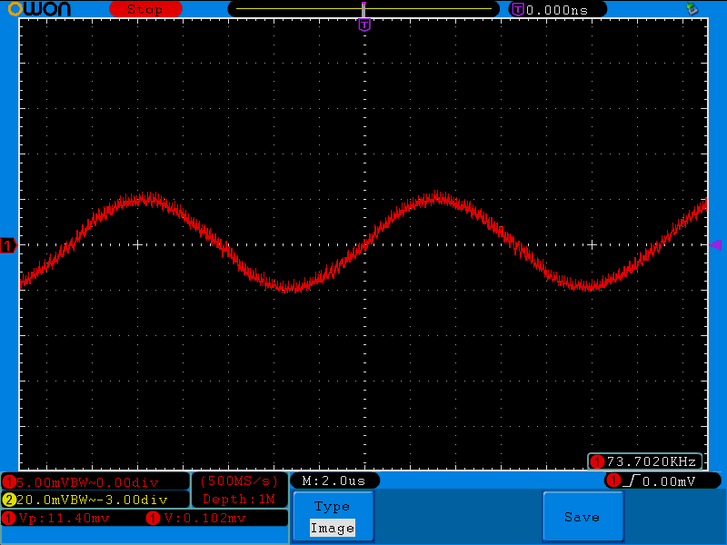
Reasonably nice and clean.

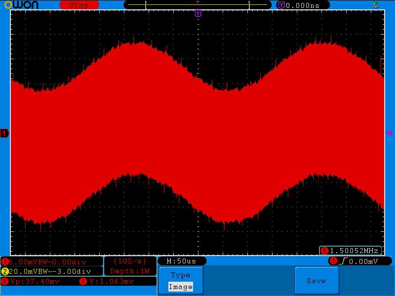
But when I use external clock, it looks horrible with small signals:


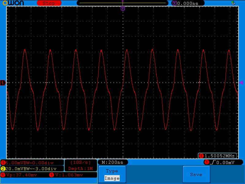
And zooming, it's surely the external clock:


Edit: added details on measurement
« Last Edit: July 04, 2014, 03:18:27 pm by jaxbird »
Analog Discovery Projects: http://www.thestuffmade.com
Youtube random project videos: https://www.youtube.com/user/TheStuffMade
 

Offline jaxbirdTopic starter

  • Frequent Contributor
  • **
  • Posts: 778
  • Country: 00
Re: Impedance Analyzer Build and Experiments
« Reply #45 on: July 04, 2014, 03:12:00 pm »
I tried separating the DGND from SGND and AGND, although the datasheet says:

Quote
IT IS RECOMMENDED TO TIE ALL SUPPLY
CONNECTIONS (PIN 9, PIN 10, AND PIN 11)
AND RUN FROM A SINGLE SUPPLY BETWEEN
2.7V AND 5.5V. IT IS ALSO RECOMMENDED TO
CONNECT ALL GROUND SIGNALS TOGETHER
(PIN 12, PIN 13, AND PIN 14).

As according to their own demo board schematic they do keep the DGND seperate, but no real improvement.  ???

GNDs should probably be joined close to the AD5933, but I believe I have a bigger problem that that, with the clock noise I'm observing.

Analog Discovery Projects: http://www.thestuffmade.com
Youtube random project videos: https://www.youtube.com/user/TheStuffMade
 

Offline jaxbirdTopic starter

  • Frequent Contributor
  • **
  • Posts: 778
  • Country: 00
Re: Impedance Analyzer Build and Experiments
« Reply #46 on: July 04, 2014, 05:11:10 pm »
And just to confirm it's not because the external clock signal got wild over/under shoot:


Not sure yet what is really causing the noise on the AD5933 feedback or how to deal with it.


Analog Discovery Projects: http://www.thestuffmade.com
Youtube random project videos: https://www.youtube.com/user/TheStuffMade
 

Offline Zad

  • Super Contributor
  • ***
  • Posts: 1013
  • Country: gb
    • Digital Wizardry, Analogue Alchemy, Software Sorcery
Re: Impedance Analyzer Build and Experiments
« Reply #47 on: July 04, 2014, 06:30:41 pm »
Have you tried reducing the clock drive level? That might drop the feed-through.

Offline jaxbirdTopic starter

  • Frequent Contributor
  • **
  • Posts: 778
  • Country: 00
Re: Impedance Analyzer Build and Experiments
« Reply #48 on: July 04, 2014, 06:41:16 pm »
Have you tried reducing the clock drive level? That might drop the feed-through.

It's a good suggestion, thanks, but I have tried to reduce it, I have a 100R resistor on the output and then I pull it down with 1k at the AD5933, but I haven't observed any improvements. It only swings 0-3V with this configuration. I can try reduce it further, but I doubt it will improve on the noise.

I'm starting to wonder maybe the AD5933 I'm using have suffered from the rough environment of prototyping, but I don't really think so as it does work fine in all other aspects.

Analog Discovery Projects: http://www.thestuffmade.com
Youtube random project videos: https://www.youtube.com/user/TheStuffMade
 

Offline dannyf

  • Super Contributor
  • ***
  • Posts: 8221
  • Country: 00
Re: Impedance Analyzer Build and Experiments
« Reply #49 on: July 04, 2014, 07:06:09 pm »
The chip is a current drive. So the issue you are seeing maybe decoupling or earthing?
================================
https://dannyelectronics.wordpress.com/


Share me

Digg  Facebook  SlashDot  Delicious  Technorati  Twitter  Google  Yahoo
Smf