I have a small utility trailer that I want to tow with my car. I don't have a truck to pick up lumber and other things that don't fit under the hatch. My car has amber turn signals and my trailer has only red tail lights. This is not a convenient set up for a common roadway mismatch. You have more wires coming out of your car than wires that go into the trailer! I went online and did a little research. Found an adapter and ordered it. These things are kind of pricey! I paid $24 shipped for a cheapo unit. Many are in the $60 range.
A week later it arrives and... I got the wrong part! This adapter is for towing a car with amber turn signals behind a motor home with red lights. I read the part description bass ackwards. I need to go from amber to red, not red to amber! I Fumblebucked up it all!
So I wasted 24 bucks... Returning it is not really worth the hassle after shipping and restocking fees. Maybe it will come in handy down the road. Hmmmm, What to do now? Lets make my own tail light adapter! How hard can it be? All I have to do is make lights go blinky blinky right?
I googled tail light adapter circuits and and discovered the XOR Gate. Here is what I want it to do.
XOR Logic Table
input + input = output
turn brake trailer
off + off = off
off + on = on
on + off = on
on + on = off
It works is like this... The Brake and turn signals go thru the circuit and work like normal if they are turned on seperately. The magic happens when the brakes and turn signal are on at the same time. While the brake is on, if the turn signal comes on, it will turn the brake light off for that corresponding side, creating the blinky effect that signals your vehicular intentions.
I found the CD4070BD 12V quad XOR gate IC to be useful for my project. Dropping to 5v for the logic is not cheaper and finding a 12V chip sure is handy! Use it to drive a couple MOSFETs and Dave's your Uncle! As I dabbled around with the schematic I was trying to figure out how to manipulate the circuit so that it could be powered from the incoming tail light signals. I have 12 volts available right there when I need it and I can't use it because I can't feedback turn signals into brake signals or brakes into turn signals. I don't want to use diodes and cause voltage drops that will dim the lights. FUSTERCLUCKED! GRRRR! I CAN'T MAKE IT WORK!!!
Things quickly became more complicated than it needed to be so I just settled on driving the circuit from an accessory port on the car battery with it's own fuse. I ordered some 12v XOR gates and some oversized MOSFET's that could easily handle the load. I bought 10 of each from china-bay for a few dollars. It will take a month but I'm not in a hurry and it's cheap. And I LOVE cheap!
While waiting for parts, the idea of powering the trailer lights from a seperate circuit was pestering me. I have to rip apart too much of the car to "properly" run a power wire for something so simple. From the battery, thru the firewall, under the dash, rip up the carpet and trim, lay wires, put it all back without screwing anything up. Bah! Too much like work! Plus, I thought about how common it is to accidentally short trailer wiring. Thus, letting the smoke escape from your MOSFET's and/or XOR gates creating a pleasant smell in your car and a probable fix-it ticket on the way home for repair.
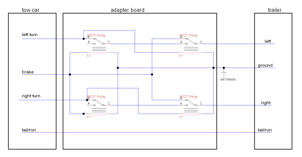
There has to be a better way! I just want a couple of lights to flash on and off at my command. Back to the drawing board! I don't remember how I came up with it but I figured out how to do this with some relay voodoo. It's just a few relays wired up to perform XOR logic on your tail lights. Everything is powered from the tail lights and no accessory power is needed! Accidental shorts will just blow your tail light fuse and won't likely cause any damage to the relays. Simple, robust, and cheap! Did I mention that I LOVE cheap!
I used four .30 cent relays and a .10 cent proto board putting my total cost of the project under 2 bucks! Though I technically wasted 6 bucks on IC's that might come in handy for future projects. And the 24 bucks on the wrong light adapter that I will probly never use. We will just discard that 30 bucks as the cost of impatience and inexperience and use this as a lesson learned for next time.
Don't make my mistakes! Save yourself time and money! Here is how to make your own tail light adapter for under 2 bucks! Schematic and pics below!
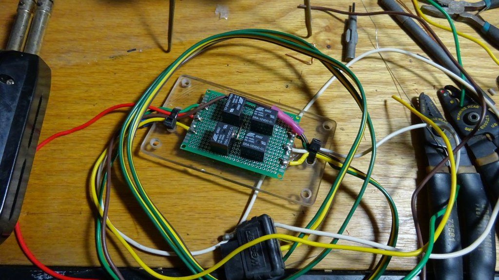
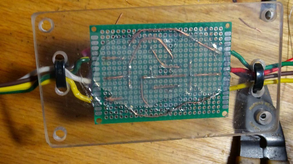
The part I used is a SRA-12VDC Relay. I had some in stock for solar projects. They cost about 30 cents each on flea-bay. I got a 10 pack for 3 bucks. You can use any 12 volt automotive SPDT relay (5 pins). Just make sure the relay you use is rated for 12 volts on the coil. Don't use wimpy hook up wire because you need to sustain some current. These relays are just 10 amps but that "should" work fine. I think the fuse would blow before they melt down. 20 amp relays are just as cheap and would be better (something like SRD-12VDC). I glued my proto board to a piece of scrap acrylic and drilled a few holes to mount with zip ties and create strain relief for the wire connections.
The board is grounded to chassis with a ring terminals on the ground wire between adapter board and trailer plug. So the ground wire goes from the board, to the chassis connection, then to the trailer plug. This makes a good strong ground connection for both sides without an extra wire.
Trailer wire color code:
Yellow = Left Turn
Green = Right Turn
Red = Brake (input from car)
Brown = Tail/Run
White = Ground
Note: Be aware of your tail light fuse rating. Most cars are 15 amps and typically max out around 7.5 amps with all the tail lights going. Add a trailer and you are basically doubling the amp load and working the system to maximum capacity. I use LED tail lights on my trailer so that the current draw is significantly decreased on my tail light fuses. If you have a big trailer with a lot of lights this can become an issue. Keep this in mind when wiring your vehicle for a trailer.
I hope you find something useful in this post! I'm sure this circuit must be handy for something else. I will surely use it in future solar projects.
Good Luck and Happy XOR Gating!