Author Topic: Need advice for ADC Buffer  (Read 23233 times)

0 Members and 1 Guest are viewing this topic.

Offline CrossphasedTopic starter

  • Regular Contributor
  • *
  • Posts: 127
  • Country: us
Need advice for ADC Buffer
« on: December 28, 2017, 08:55:32 pm »
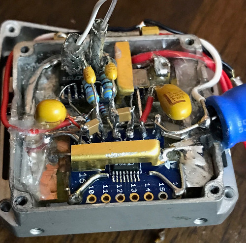
I'm putting together a precision voltmeter w/ a 24 bit ADC, and I'm struggling to get the buffer to the ADC  correct. The ADC used is the LTC2440, with a 5V LTC6655 reference. The assembly has been completed, but I need to re-work the ADC input buffer section. Here's a few pictures:
The ADC and the LTC6655 are covered by the gold shields


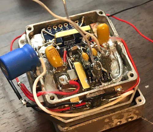
The analog and digital grounds are seperate, and the shield seperates the analog from the digital side


The 5V supply to the ADC is from an LT1461, and the (+) power supply to the buffers is from an LT3080. I'd like to use a single supply to the buffer amps if possible. Everything is powered from a 9V battery. The voltmeter is only used to measure positive DC voltages.

I'm having trouble with the input buffer to the ADC, specifically how to reference the differential inputs to the ground of the buffers. I'm somewhat new to op-amps. What I'm looking for is unity gain, and can handle a common mode voltage of +10-30 V. The desired output of the buffer is 0 -5 V. A little above 0 and a little less than 5 is ok and can be removed with calibration. On my first attempt I made the mistake picking opamps without taking into account how far they were able to swing compared to their power supply. So this is my second attempt. I went back to the datasheet for the 2440, and examined their buffer circuit using chopper amps:

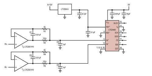
My plan is to use this circuit for the buffer, and I've got the LTC2051 here ready to use. To validate before installing, I made a test circuit using this schematic with LTC1050's, and found the output to bounce around wildly if the inputs didn't have a DC path to ground. A single supply of +6V was used for the 1050's, and a single AA battery of ~1.58 was applied to the inputs. I tried some other configurations as well, here's my results so far:

1)  Referenced both inputs to ground using 10K resistors


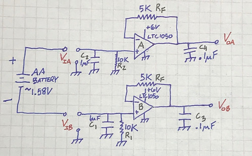
I measured the input voltages Via and Vib with reference to ground. Vib turned out to be negative and I quickly realized I had made a voltage divider with the center grounded:

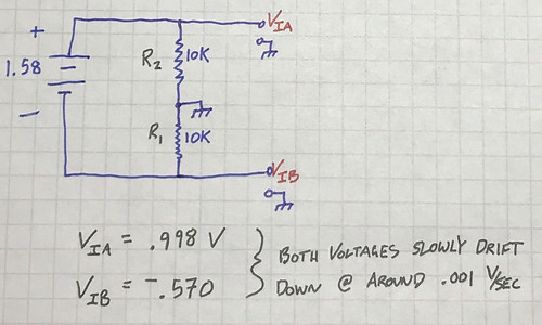
There isn't a negative supply so the output Vob was ~16 mV above ground, and Voa was ~1 V. No good.  I was somewhat surprised to see the voltage wasn't split evenly.  Maybe apply +2.5 V to the middle of R1 and R2 to correct the offset?

2)  Removed the ground connection between R1 and R2
I've read the buffers always need a DC return for the inputs, so R1 and R2 were connected to each other, essentially floating relative to the buffer grounds:

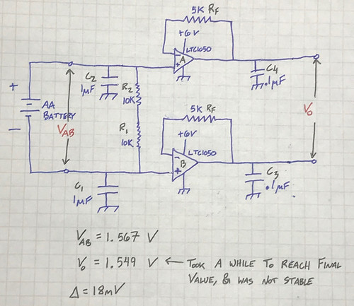
This produced better results, but it was clear the output was not very stable. It took quite some time to reach the final value, slowly rising to it. Blowing on the circuit would cause the output to jump 10-20 mV. Also, the offset of 18 mV,  is that normal?

3)  Grounded the battery to the buffer ground. This produced the best results

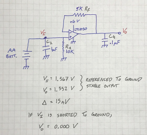
I see an offset of 15 mV again, is that a normal condition? The datasheet of the 1050 states an offset voltage of around 5 microvolts. If I'm doing something wrong here please let me know! Also if any of the passive component values are incorrect please advise. Circuit #3 produced the best results but ideally I'd like to avoid tying the V- input to ground. There is a high common mode voltage in the application, anywhere from 10-30VDC.

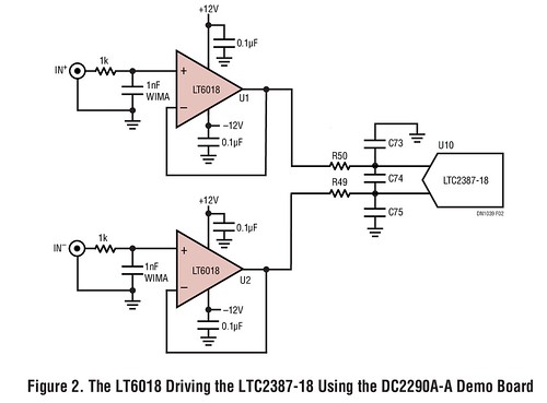
I've read through various datasheets looking for ideas, but I'm hoping someone more experienced than I can steer me in the right direction. Here's a few different buffer circuits I've found:


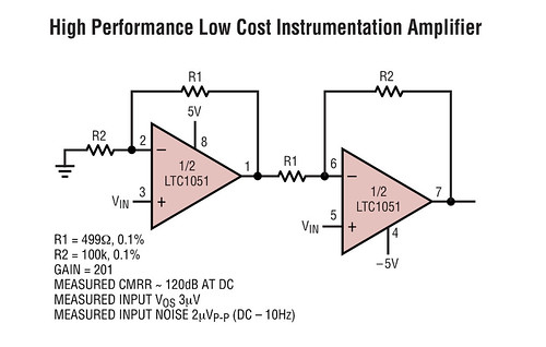
Looks like they get away with floating the inputs here?


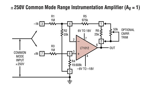
Interesting unity gain with CMRR trim


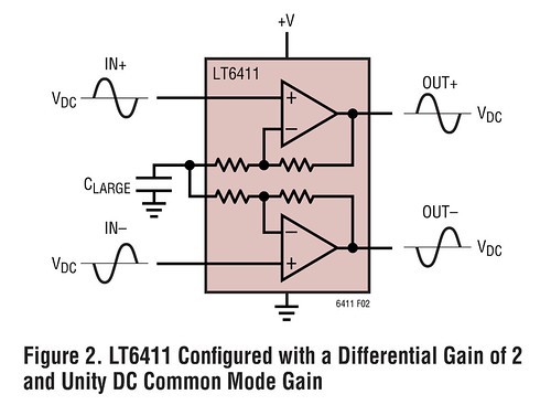
This circuit doesnt look all that different from my circuit #2, but with an added cap to ground


Any expertise you can offer would be very much appreciated! Thanks!


Offline fcb

  • Super Contributor
  • ***
  • Posts: 2117
  • Country: gb
  • Test instrument designer/G1YWC
    • Electron Plus
Re: Need advice for ADC Buffer
« Reply #1 on: December 28, 2017, 09:11:35 pm »
If you need a high-common mode voltage either:

1. Float your whole ADC block - this will give you the maximum accuracy, at the expense of complexity.
2. Use some potential dividers and measure each side of the battery, you'll through away some resolution and you'll have to watch the TC matching of the potential dividers.
3. Build a high-voltage diff amp to bring your difference down to a more ADC friendly level.

Choose your poison.
https://electron.plus Power Analysers, VI Signature Testers, Voltage References, Picoammeters, Curve Tracers.
 

Offline CrossphasedTopic starter

  • Regular Contributor
  • *
  • Posts: 127
  • Country: us
Re: Need advice for ADC Buffer
« Reply #2 on: December 28, 2017, 10:17:54 pm »
If you need a high-common mode voltage either:

1. Float your whole ADC block - this will give you the maximum accuracy, at the expense of complexity.
2. Use some potential dividers and measure each side of the battery, you'll through away some resolution and you'll have to watch the TC matching of the potential dividers.
3. Build a high-voltage diff amp to bring your difference down to a more ADC friendly level.

Choose your poison.

Thank you fcb,
How would I go about option number 1? That's the root of my question in this thread. What topology would you use to accomplish floating the ADC block?
 

Offline fcb

  • Super Contributor
  • ***
  • Posts: 2117
  • Country: gb
  • Test instrument designer/G1YWC
    • Electron Plus
Re: Need advice for ADC Buffer
« Reply #3 on: December 28, 2017, 11:30:18 pm »
You have two problems with #1.

a. isolate the digital signals between the microcontroller and your ADC - easily solved with a digital isolator, something like the Si8661/2, ISO7240 or similar. I've been quite impressed by the low-jitter of the MAX1443x range recently.

b. isolate the power to the ADC - less easily solved, solutions range from one of those $4 SIP 1W isolators (pretty noisy), building your own DC/DC with off-the-shelf magnetics through to low capacitance, high voltage isolation using my own wound transformers on coated ferrite cores.
https://electron.plus Power Analysers, VI Signature Testers, Voltage References, Picoammeters, Curve Tracers.
 

Offline danadak

  • Super Contributor
  • ***
  • Posts: 1875
  • Country: us
  • Reactor Operator SSN-583, Retired EE
Re: Need advice for ADC Buffer
« Reply #4 on: December 28, 2017, 11:40:22 pm »
Some questions -

First your LSB = 300 nV

1) What is your design goal for accuracy ? Is it absolute accuracy or relative.
2) What is the T range the accuracy spec has to operate over ?

You have to perform an end to end error analysis to see if your goals can be met.
@24 bits you will quickly find your accuracy degrades, over T, to << 16 bits, w/o
extraordinary measures. PSRR, Linearity, Offsets V and I, thermoelectric effects,
electro-chemical effects......


Here are some ap notes covering basics for many of these error topics -


https://www.dropbox.com/s/plck7e95v7pw33c/CMR%20Analysis%20IA.pdf?dl=0


https://www.dropbox.com/s/aq8pyz7d9oc8r5t/analog_digital_conversion.zip?dl=0


Regards, Dana.


Love Cypress PSOC, ATTiny, Bit Slice, OpAmps, Oscilloscopes, and Analog Gurus like Pease, Miller, Widlar, Dobkin, obsessed with being an engineer
 
The following users thanked this post: Vgkid

Offline CrossphasedTopic starter

  • Regular Contributor
  • *
  • Posts: 127
  • Country: us
Re: Need advice for ADC Buffer
« Reply #5 on: December 29, 2017, 08:10:21 am »
Some questions -

First your LSB = 300 nV

1) What is your design goal for accuracy ? Is it absolute accuracy or relative.
2) What is the T range the accuracy spec has to operate over ?

You have to perform an end to end error analysis to see if your goals can be met.
@24 bits you will quickly find your accuracy degrades, over T, to << 16 bits, w/o
extraordinary measures. PSRR, Linearity, Offsets V and I, thermoelectric effects,
electro-chemical effects......


Here are some ap notes covering basics for many of these error topics -


https://www.dropbox.com/s/plck7e95v7pw33c/CMR%20Analysis%20IA.pdf?dl=0


https://www.dropbox.com/s/aq8pyz7d9oc8r5t/analog_digital_conversion.zip?dl=0


Regards, Dana.

Thank you Dana,
The references are much appreciated! Ive read and enjoyed the Linear app note AN86 before so I'm sure I'll enjoy these.
Regarding your questions,
    1. Striving for relative accuracy, not absolute. I'd like to get 18 bits of usable resolution if possible. My intention is to use the 2440 in its 7 Hz high resolution mode, then    apply some averaging techniques.
    2. The environment will be indoors, at room temperature. I'd limit max temperature swing in a data capture session to 10 C.

My intent is to calibrate out any offsets, then see what kind of results I get. I purchased some LTC6655's at a couple other different voltages, so the idea is to calibrate the 24 bit ADC to a 6.5 digit bench multimeter.  The LT1461 was chosen to provide a stable supply to the 2440, and the housing has a metal cover that goes over it to seal any air flow. If the measurements seem acceptable, I have considered temperature stabilizing the metal housing with a Peltier element. We'll see. Any other suggestions are welcome! Thank you for your time
 

Offline CrossphasedTopic starter

  • Regular Contributor
  • *
  • Posts: 127
  • Country: us
Re: Need advice for ADC Buffer
« Reply #6 on: December 29, 2017, 08:18:29 am »
You have two problems with #1.

a. isolate the digital signals between the microcontroller and your ADC - easily solved with a digital isolator, something like the Si8661/2, ISO7240 or similar. I've been quite impressed by the low-jitter of the MAX1443x range recently.

b. isolate the power to the ADC - less easily solved, solutions range from one of those $4 SIP 1W isolators (pretty noisy), building your own DC/DC with off-the-shelf magnetics through to low capacitance, high voltage isolation using my own wound transformers on coated ferrite cores.

fcb,
I'll check out that MAX1443 part, thank you for the tip! To isolate the ADC I currently power all the components from a 9V battery. For a more long term solution I've considered two options:
1. A mains stepdown/isolation transformer. I made a note of your comment to insulate the both the core, and the windings from each other.
2. One of those cell phone USB battery packs. I've read those things have boost converters in them so I'm not sure how difficult it would be to filter that noise out.

Thanks for your helpful comments, they are much appreciated!
 

Offline danadak

  • Super Contributor
  • ***
  • Posts: 1875
  • Country: us
  • Reactor Operator SSN-583, Retired EE
Re: Need advice for ADC Buffer
« Reply #7 on: December 29, 2017, 12:09:17 pm »
Just a thought but a PSOC 5LP has an onboard 20 bit DelSig ADC
with a differential input. In fact it also has a buffer that can G up
to x 8. Plus a digital filter to filter the output stream and DMA to
handle that all in HW to free up processor  for other tasks. And an
onboard +/- .1% reference for the ADC. Plus tons of other stuff.

Low cost board as well -


http://www.cypress.com/documentation/development-kitsboards/cy8ckit-059-psoc-5lp-prototyping-kit-onboard-programmer-and


Regards, Dana.

« Last Edit: December 29, 2017, 12:14:12 pm by danadak »
Love Cypress PSOC, ATTiny, Bit Slice, OpAmps, Oscilloscopes, and Analog Gurus like Pease, Miller, Widlar, Dobkin, obsessed with being an engineer
 

Offline David Hess

  • Super Contributor
  • ***
  • Posts: 16615
  • Country: us
  • DavidH
Re: Need advice for ADC Buffer
« Reply #8 on: December 29, 2017, 02:40:57 pm »
Multimeters use the configuration shown in your example 3 with common shared between the input signal and the analog circuits.  That you had 15 millivolts of offset shows that there was a major problem in your implementation.  The LTC1050 is unlikely to be stable with all capacitive loads so maybe it is oscillating.  Try adding a 47 ohm resistor in series with 0.1uF C4 or replacing C4 with a 10uF solid tantalum or aluminum electrolytic.  If it is oscillating, an oscilloscope should reveal it.

The input to the LTC1050 would normally include a parrallel RC network in series with the non-inverting input to protect against damaging overload.  500k and 1000pF would be typical however the input bias current of the chopper stabilized LTC1050 is higher than a simpler FET input amplifier so a lower resistance and higher capacitance might be necessary.  The input shunt resistance comes before this so it contributes no error except for loading the source.

Despite having a rail-to-rail output voltage range, the LTC1050 is not going to work correctly at low output voltages close to the negative supply.  An asymmetric input range could be accommodated by using a different termination voltage.  For instance if the negative differential input of the ADC was held at about 1 Vbe above the negative supply and this point was used for the external common, then the LTC1050 could operate all the way through 0 volts accurately.  I have seen some multimeter designs which operate this way.

If a balanced input using two LTC1050 buffers is desired, then common mode restrictions are going to require the input shunt resistors to be connected to a voltage midway between the common mode input limits of 0 and +2.7 volts when operating on a +5 volt supply or about +1.35 volts.
 
The following users thanked this post: Inverted18650

Offline CrossphasedTopic starter

  • Regular Contributor
  • *
  • Posts: 127
  • Country: us
Re: Need advice for ADC Buffer
« Reply #9 on: December 30, 2017, 07:02:32 am »
Multimeters use the configuration shown in your example 3 with common shared between the input signal and the analog circuits.  That you had 15 millivolts of offset shows that there was a major problem in your implementation.  The LTC1050 is unlikely to be stable with all capacitive loads so maybe it is oscillating.  Try adding a 47 ohm resistor in series with 0.1uF C4 or replacing C4 with a 10uF solid tantalum or aluminum electrolytic.  If it is oscillating, an oscilloscope should reveal it.

The input to the LTC1050 would normally include a parrallel RC network in series with the non-inverting input to protect against damaging overload.  500k and 1000pF would be typical however the input bias current of the chopper stabilized LTC1050 is higher than a simpler FET input amplifier so a lower resistance and higher capacitance might be necessary.  The input shunt resistance comes before this so it contributes no error except for loading the source.

Despite having a rail-to-rail output voltage range, the LTC1050 is not going to work correctly at low output voltages close to the negative supply.  An asymmetric input range could be accommodated by using a different termination voltage.  For instance if the negative differential input of the ADC was held at about 1 Vbe above the negative supply and this point was used for the external common, then the LTC1050 could operate all the way through 0 volts accurately.  I have seen some multimeter designs which operate this way.

If a balanced input using two LTC1050 buffers is desired, then common mode restrictions are going to require the input shunt resistors to be connected to a voltage midway between the common mode input limits of 0 and +2.7 volts when operating on a +5 volt supply or about +1.35 volts.

Wow David,
Thanks for all the info! Very kind of you to help me out! What I understand you saying, is the ADC/buffer ground reference should be tied to the input common reference for the single ended circuit, and in the balanced circuit, an offset voltage should be connected in between the 10K resistors. I'm curious how you came up with the values for the common mode voltage of 1.35 V though. For a 0-5V input, the common mode range in between the two 10K resistors would be 2.5V right? So if the midpoint was instead tied to ground, and 5V applied across the inputs, there should be +2.5V on the top buffer and -2.5V on the bottom buffer, relative to the ADC ground. I'm missing something so I'm wondering what that is.

For a DC/low frequency application, do you see any benefit to the balanced setup? I'm using the LTC2051, which has two opamps on the part, so I have the extra buffer there if it is advantageous to use the balanced setup. Which circuit would you recommend?

After reading your reply, I made some changes to reflect what you advised. Is this what you had in mind?
Balanced


Single Ended


I considered an asymmetric PS for the buffers - I was wondering about that. My plan was to calibrate in software whatever offset was present for 0 V input, but are you saying the LTC2051 will not perform well when the input is close to 0? It wouldn't be too much trouble to add say a -1 V supply, but you are suggesting putting a diode or bjt in between the opamps and ground reference. Is one better than the other?

Thanks for your help, I very much appreciate it!
 

Offline David Hess

  • Super Contributor
  • ***
  • Posts: 16615
  • Country: us
  • DavidH
Re: Need advice for ADC Buffer
« Reply #10 on: December 30, 2017, 03:02:45 pm »
I'm curious how you came up with the values for the common mode voltage of 1.35 V though. For a 0-5V input, the common mode range in between the two 10K resistors would be 2.5V right? So if the midpoint was instead tied to ground, and 5V applied across the inputs, there should be +2.5V on the top buffer and -2.5V on the bottom buffer, relative to the ADC ground. I'm missing something so I'm wondering what that is.

The common mode input range of the LTC1050 is from 0 to 2.7 volts when operating on 5 volts.  Half of 2.7 volts is 1.35 volts.

Quote
For a DC/low frequency application, do you see any benefit to the balanced setup? I'm using the LTC2051, which has two opamps on the part, so I have the extra buffer there if it is advantageous to use the balanced setup. Which circuit would you recommend?

The balanced setup has:

1. A high and equal input impedance on both inputs which may improve common mode rejection.
2. Twice as much noise from the input circuits.
3. Twice the input voltage range which includes negative voltages.

Balanced inputs are usually only found on precision voltmeters when the source has a balanced output like with certain sensors.  Most digital voltmeters have an unbalanced input but the common is floating with respect to ground.

Quote
After reading your reply, I made some changes to reflect what you advised. Is this what you had in mind?

They look fine but those series RC snubbers are not required if you are using the 100 ohm resistors and capacitive feedback to drive the 1uF capacitors.

Quote
I considered an asymmetric PS for the buffers - I was wondering about that. My plan was to calibrate in software whatever offset was present for 0 V input, but are you saying the LTC2051 will not perform well when the input is close to 0? It wouldn't be too much trouble to add say a -1 V supply, but you are suggesting putting a diode or bjt in between the opamps and ground reference. Is one better than the other?

The problem is that while the input common mode range extends below the negative supply, the output voltage range does not so at low voltages, the output from the operational amplifier saturates.  If you are never measuring near zero then this is irrelevant.

Since the ADC had a differential input, the simple solution is to tie the ADC's negative input to a voltage slightly higher than the negative supply voltage and then use that point for the common input.  Now the operational amplifier can pull the ADC's positive input below the "fake" ground point and a zero input voltage is not a problem at all.  The accuracy of this fake common voltage is not important so a diode might be used to generate it.
 

Offline fcb

  • Super Contributor
  • ***
  • Posts: 2117
  • Country: gb
  • Test instrument designer/G1YWC
    • Electron Plus
Re: Need advice for ADC Buffer
« Reply #11 on: December 30, 2017, 03:22:06 pm »
If you are measuring the output of a cell, this is likely to be very low impedance.

Why bother with the buffer at all?  Perhaps just have a 100R/1uF low-pass on the front straight into your ADC.
https://electron.plus Power Analysers, VI Signature Testers, Voltage References, Picoammeters, Curve Tracers.
 

Offline Marco

  • Super Contributor
  • ***
  • Posts: 6721
  • Country: nl
Re: Need advice for ADC Buffer
« Reply #12 on: December 30, 2017, 04:47:09 pm »
A single ended input gives you the highest input impedance.

The resistor divider you use in the balanced case will have a far lower impedance than a cmos/jfet input.

PS. for DC, input impedance for a floating meter with a single ended input is obviously still balanced, only a single path for current to take.
« Last Edit: December 30, 2017, 05:00:04 pm by Marco »
 

Offline CrossphasedTopic starter

  • Regular Contributor
  • *
  • Posts: 127
  • Country: us
Re: Need advice for ADC Buffer
« Reply #13 on: December 30, 2017, 08:48:25 pm »
The common mode input range of the LTC1050 is from 0 to 2.7 volts when operating on 5 volts.  Half of 2.7 volts is 1.35 volts.
Ok I see what you're getting at now, thank you. Look up the 2051 datasheet, I see the common mode range is 0 to Vs -1.3V.  So for a 6V supply the range should be 0 to 4.7VCM. I think I'll increase the supply to 6.5V.
Looking in the datasheet for the bias currents for the 2051, it looks like they can be up to around 100 pA .  So does 100K seem ok on the input?

Regarding topology, I think I'm going to go the unbalanced route, it seems like the most straightforward. I had a thought- reading the datasheets for various chopper amps, it seems you can parallel them to reduce noise. Noise is reduced by sqrt of # of amps paralleled. On the 2051 I'll have an extra one sitting there, would it be wise to parallel in the unbalanced config? Or are there some unseen complications?

Quote
The problem is that while the input common mode range extends below the negative supply, the output voltage range does not so at low voltages, the output from the operational amplifier saturates.  If you are never measuring near zero then this is irrelevant.

Since the ADC had a differential input, the simple solution is to tie the ADC's negative input to a voltage slightly higher than the negative supply voltage and then use that point for the common input.  Now the operational amplifier can pull the ADC's positive input below the "fake" ground point and a zero input voltage is not a problem at all.  The accuracy of this fake common voltage is not important so a diode might be used to generate it.
Got it thank you. I want to make sure I understand you right- in this case the input common, and the ADC would sit above ground by 1 diode drop, while the opamp would connect directly to ground. Sound right?
 

Offline CrossphasedTopic starter

  • Regular Contributor
  • *
  • Posts: 127
  • Country: us
Re: Need advice for ADC Buffer
« Reply #14 on: December 30, 2017, 09:02:30 pm »
If you are measuring the output of a cell, this is likely to be very low impedance.

Why bother with the buffer at all?  Perhaps just have a 100R/1uF low-pass on the front straight into your ADC.

Hi fcb,

yes if I was just measuring a battery i wouldn't bother with a buffer. Unfortunately that is not the case. I was just using the battery as a stable voltage source to test the circuit. The inputs are taken off a voltage divider with a high source impedance, making the buffer necessary. I'm hoping using the buffer amp will afford a bit of protection to the adc as well. I'd much rather replace the op amps than the adc! It seems the 100K resistor on the input that David suggested will help as well. Is additional protection usually necessary? I've seen some people use diodes to either rail to clamp the inputs. I'm curious if the diode leakage has much of an effect on readings. What is generally done? I also remember reading using a diode connected jfet to clamp the inputs.
 

Offline David Hess

  • Super Contributor
  • ***
  • Posts: 16615
  • Country: us
  • DavidH
Re: Need advice for ADC Buffer
« Reply #15 on: December 30, 2017, 09:49:22 pm »
The common mode input range of the LTC1050 is from 0 to 2.7 volts when operating on 5 volts.  Half of 2.7 volts is 1.35 volts.

Ok I see what you're getting at now, thank you. Look up the 2051 datasheet, I see the common mode range is 0 to Vs -1.3V.  So for a 6V supply the range should be 0 to 4.7VCM. I think I'll increase the supply to 6.5V.

Your first schematic showed the LTC1050 so I went by that.

Quote
Looking in the datasheet for the bias currents for the 2051, it looks like they can be up to around 100 pA .  So does 100K seem ok on the input?

You mean for the series resistance?  100 picoamps through 100 kilohms is 10 microvolts which seems reasonable to me.  It depends on how much error you can accept.  Adding that series resistor will contribute a lot to preventing damage to the amplifier input.  Bypassing it with a capacitor keeps the noise low so there is no reason not to include it.

Quote
Regarding topology, I think I'm going to go the unbalanced route, it seems like the most straightforward. I had a thought- reading the datasheets for various chopper amps, it seems you can parallel them to reduce noise. Noise is reduced by sqrt of # of amps paralleled. On the 2051 I'll have an extra one sitting there, would it be wise to parallel in the unbalanced config? Or are there some unseen complications?

Chopper amplifiers are a special case do not always work well in parallel but the LTC2051 is an exception as shown in the datasheet.  Do not try that with chopper amplifiers in separate packages unless their clocks are synchronized.

Quote
Got it thank you. I want to make sure I understand you right- in this case the input common, and the ADC would sit above ground by 1 diode drop, while the opamp would connect directly to ground. Sound right?

The input common and ADC negative input sit 1 diode drop above ground so when the inputs are shorted together, the operational amplifier input, operational amplifier output, and ADC positive input are still one diode voltage drop above ground so there will be no problems with saturation when the input is zero volts or even a little bit negative.

This all assumes that the battery is isolated from the measurement circuit and that they do not share a common ground.  If they do share a common ground, then another method will have to be used like powering the operational amplifier and perhaps ADC with a small negative voltage or adding a current sink to the operational amplifier output which has negative compliance.
 
The following users thanked this post: Inverted18650

Offline Marco

  • Super Contributor
  • ***
  • Posts: 6721
  • Country: nl
Re: Need advice for ADC Buffer
« Reply #16 on: December 30, 2017, 09:58:13 pm »
You don't generally use choppers on volt meters, because you're not really worried about higher frequencies and Nyquist. Just put a mux before the buffer and ground it to find the offset in between every measurement. Also you want about 500k series resistance to make it mains proof and thus prefer very little bias current.
 

Offline David Hess

  • Super Contributor
  • ***
  • Posts: 16615
  • Country: us
  • DavidH
Re: Need advice for ADC Buffer
« Reply #17 on: December 31, 2017, 04:19:39 am »
You don't generally use choppers on volt meters, because you're not really worried about higher frequencies and Nyquist. Just put a mux before the buffer and ground it to find the offset in between every measurement. Also you want about 500k series resistance to make it mains proof and thus prefer very little bias current.

That is true but I figured Crossphased wants to keep it simple.

A chopper stabilized amplifier would still be used at the highest resolution to reduce 1/f noise which automatic zero has no effect on.  But it is amazing how well a low performance CMOS amplifier can perform while inside of an automatic zero loop.

One of my favorite multimeters uses a JFET input stage without automatic zero yet still achieves 100 microvolt resolution with good stability and accuracy; I like it because without automatic zero, it does not suffer from charge pumping.  A modern implementation could use an LT1012 for even better performance than most JFET designs.  The LT1012 is a bipolar input operational amplifier but since its input bias current is more stable than a JFET over temperature, it actually outperforms most of them in many respects.
 

Offline fcb

  • Super Contributor
  • ***
  • Posts: 2117
  • Country: gb
  • Test instrument designer/G1YWC
    • Electron Plus
Re: Need advice for ADC Buffer
« Reply #18 on: December 31, 2017, 12:01:23 pm »
If you are measuring the output of a cell, this is likely to be very low impedance.

Why bother with the buffer at all?  Perhaps just have a 100R/1uF low-pass on the front straight into your ADC.

Hi fcb,

yes if I was just measuring a battery i wouldn't bother with a buffer. Unfortunately that is not the case. I was just using the battery as a stable voltage source to test the circuit. The inputs are taken off a voltage divider with a high source impedance, making the buffer necessary. I'm hoping using the buffer amp will afford a bit of protection to the adc as well. I'd much rather replace the op amps than the adc! It seems the 100K resistor on the input that David suggested will help as well. Is additional protection usually necessary? I've seen some people use diodes to either rail to clamp the inputs. I'm curious if the diode leakage has much of an effect on readings. What is generally done? I also remember reading using a diode connected jfet to clamp the inputs.

Diode leakage on protection circuits is quite an interesting topic. I've used C-B's on 2N3904's before as clamps (robust and very low leakage), BAV199's in more generic roles (<5nA), even looked at BFT25's (pretty fragile but very low leakage).

https://electron.plus Power Analysers, VI Signature Testers, Voltage References, Picoammeters, Curve Tracers.
 

Offline David Hess

  • Super Contributor
  • ***
  • Posts: 16615
  • Country: us
  • DavidH
Re: Need advice for ADC Buffer
« Reply #19 on: December 31, 2017, 02:49:51 pm »
Diode leakage on protection circuits is quite an interesting topic. I've used C-B's on 2N3904's before as clamps (robust and very low leakage), BAV199's in more generic roles (<5nA), even looked at BFT25's (pretty fragile but very low leakage).

For better protection, external low leakage diodes could be used for clamps however most operational amplifiers including the LTC1050 and LTC2051 include internal clamp diodes which may be relied on for a moderate amount of protection.
 

Offline CrossphasedTopic starter

  • Regular Contributor
  • *
  • Posts: 127
  • Country: us
Re: Need advice for ADC Buffer
« Reply #20 on: December 31, 2017, 08:53:16 pm »
I want to say thank you to everyone has helped out so far. You guys are great!

Yesterday I put together a test circuit with the paralleled 2051's. Today I'l test it, and post here afterwards with the results. Here's the test circuit:


And here's the schematic of it:


As always, any constructive criticism is welcomed!
« Last Edit: December 31, 2017, 08:55:01 pm by Crossphased »
 

Offline David Hess

  • Super Contributor
  • ***
  • Posts: 16615
  • Country: us
  • DavidH
Re: Need advice for ADC Buffer
« Reply #21 on: December 31, 2017, 09:05:08 pm »
It would be better to connect each output to the 1uF capacitor through a separate 100 ohm resistor as shown in the datasheet application example.  If they are connected directly together, the operational amplifiers will fight and not share the load current.
 

Offline CrossphasedTopic starter

  • Regular Contributor
  • *
  • Posts: 127
  • Country: us
Re: Need advice for ADC Buffer
« Reply #22 on: December 31, 2017, 10:41:08 pm »
It would be better to connect each output to the 1uF capacitor through a separate 100 ohm resistor as shown in the datasheet application example.  If they are connected directly together, the operational amplifiers will fight and not share the load current.

Got it, thank you. Will do for the final implementation
 

Offline CrossphasedTopic starter

  • Regular Contributor
  • *
  • Posts: 127
  • Country: us
Results
« Reply #23 on: December 31, 2017, 11:01:56 pm »
Just had a chance to test... and it is working well. I used a AA battery to temporarily generate the negative PS for the op amps. Battery voltage ~ 1.6V

Here's what I observed.

Initially, I measured directly at the output of the opamps, no 100 Ohm resistor or 1uF cap:
Input left floating, output ~ 0.0008 V
Inputs shorted, output ~0.0002 V

Then added a 10 uF electrolytic across the output, as David previously suggested:
Input left floating, output = 0.000025 V
Input shorted, output = 0.000025 V

Then used a AA battery to provide an input voltage to the circuit.
 Input voltage: 1.60615 V
 Output of op amps: 1.60615 V

Success! After watching for a period of time, The output always tracks the input +-.00001 V. I'm quite pleased with that!  There is one thing that slightly puzzles me though, BOTH the input and output have been slowly drifting upward . Initial measurement was @ 1.60615 V, it drifted up to 1.60640 V @ a rate of .00001 V per second. Then drifted up to 1.600670 @ .00001 V per 2-3 seconds. Now it is at 1.60697 V and moves every 10 seconds or so. I've touched the circuit in various places and also blowed on it, and the output doesnt change at all. Just a slow drift. Any ideas on that?

Here's the circuit:


Offline David Hess

  • Super Contributor
  • ***
  • Posts: 16615
  • Country: us
  • DavidH
Re: Results
« Reply #24 on: January 01, 2018, 12:03:27 am »
Success! After watching for a period of time, The output always tracks the input +-.00001 V. I'm quite pleased with that!

Chopper stabilized amplifiers are almost magical.

Quote
There is one thing that slightly puzzles me though, BOTH the input and output have been slowly drifting upward . Initial measurement was @ 1.60615 V, it drifted up to 1.60640 V @ a rate of .00001 V per second. Then drifted up to 1.600670 @ .00001 V per 2-3 seconds. Now it is at 1.60697 V and moves every 10 seconds or so. I've touched the circuit in various places and also blowed on it, and the output doesnt change at all. Just a slow drift. Any ideas on that?

Thermocouple and leakage effects can cause odd long term drift problems.  The batteries might be recovering from a load or changing their output do to temperature or aging.


Share me

Digg  Facebook  SlashDot  Delicious  Technorati  Twitter  Google  Yahoo
Smf