Author Topic: Non Volatile Flip-Flop  (Read 6447 times)

0 Members and 1 Guest are viewing this topic.

Offline @rtTopic starter

  • Super Contributor
  • ***
  • Posts: 1059
Non Volatile Flip-Flop
« on: December 05, 2016, 12:45:09 pm »
Hi Guys :)

I was wondering if anyone could make sense of this :D
I’ve spend a few days trying to figure it out. I don’t even think it’s a flip flop, let alone a non volatile one!

There are a few parts about the schematic that could be interpreted different ways,
such as whether or not crossing lines are interconnected,
Where Q & !=Q come from, and if you drew current from anywhere, it seems it would mess up a transistor circuit,
so where are the outputs then?

In practice, if I connect the top two crossing lines under the 12R resistors, both LEDs light, and the NPN transistors get hot.
Otherwise no LEDs light, and the inputs do nothing in any case.

For now, I’ve just linked wire to replace the cores to try figuring the flip flop out.

« Last Edit: December 05, 2016, 12:46:46 pm by @rt »
 

Offline mikeselectricstuff

  • Super Contributor
  • ***
  • Posts: 13748
  • Country: gb
    • Mike's Electric Stuff
Re: Non Volatile Flip-Flop
« Reply #1 on: December 05, 2016, 12:59:00 pm »
This will be very dependent on the magnetic characteristics of the core materials - highly unlikey to be standard ferrites
Youtube channel:Taking wierd stuff apart. Very apart.
Mike's Electric Stuff: High voltage, vintage electronics etc.
Day Job: Mostly LEDs
 

Offline @rtTopic starter

  • Super Contributor
  • ***
  • Posts: 1059
Re: Non Volatile Flip-Flop
« Reply #2 on: December 05, 2016, 01:01:12 pm »
HI :) Yes I have plenty of square curve hysteresis cores left from when I did a core RAM.
I realise there are different speeds as time progressed, but unable to find out what the 50-mil specification actually means.
Mine are very small, perhaps 1-1.5mm diameter.

ps.. even if they are wrong, it isn’t a flip-flop until you can read an output from it.
« Last Edit: December 05, 2016, 01:05:03 pm by @rt »
 

Offline mikeselectricstuff

  • Super Contributor
  • ***
  • Posts: 13748
  • Country: gb
    • Mike's Electric Stuff
Re: Non Volatile Flip-Flop
« Reply #3 on: December 05, 2016, 01:20:18 pm »
HI :) Yes I have plenty of square curve hysteresis cores left from when I did a core RAM.
I realise there are different speeds as time progressed, but unable to find out what the 50-mil specification actually means.
Mine are very small, perhaps 1-1.5mm diameter.

ps.. even if they are wrong, it isn’t a flip-flop until you can read an output from it.
probably 50 mil = 50 thousandths of an inch, so about the size you have.

Youtube channel:Taking wierd stuff apart. Very apart.
Mike's Electric Stuff: High voltage, vintage electronics etc.
Day Job: Mostly LEDs
 

Offline @rtTopic starter

  • Super Contributor
  • ***
  • Posts: 1059
Re: Non Volatile Flip-Flop
« Reply #4 on: December 05, 2016, 01:25:05 pm »
Now I’m thinking Q & !=Q are just labels for each side of the circuit, and not necessarily where it’s read from,
but it does say it provides non destructive read out.
 

Offline Ian.M

  • Super Contributor
  • ***
  • Posts: 12860
Re: Non Volatile Flip-Flop
« Reply #5 on: December 05, 2016, 02:19:09 pm »
The top two (NPN) transistors are configured as a fairly conventional bipolar flip-flop. The crossing wires next to Q and /Q should have a dot as it doesn't make sense unless they are joined. The crossing base circuit wires in the middle are NOT joined.  The cores in the emitter circuits slow or speed up switch-on at powerup so making it resume its previous state.  J and K are the inputs and are -ve edge triggered.  If the corresponding NPN transistor is on, the PNP transistor has negligable base drive and a -ve edge on the input will pulse on the PNP transitor turning the NPN transistor off.  If the NPN transistor is off, the 1K resistor biasses the PNP transistor hard off so that input has no effect.   Complimentary outputs would be from Q and /Q, but their drive capability is fairly limited.

If I was trying to reproduce it with modern parts, I'd be very suspicious of the NPN collector and base resistor values - they appear to be an order of magnitude too low for the transistor ratings 
 

Offline @rtTopic starter

  • Super Contributor
  • ***
  • Posts: 1059
Re: Non Volatile Flip-Flop
« Reply #6 on: December 05, 2016, 04:05:20 pm »
Thanks Ian :)
A bit of progress, the flip flop now works very reliably, but favours one side when powered on.
That might be due to whatever slightly different component tolerances on each side rather than cores,
but I wasn’t sure the cores were turned right when I wound them.
The right side core is difficult to interpret, and I did change my mind at the last minute,
and passed the single wire through the top rather than the bottom (to effectively change the turns direction of the multiple winding).. I think.

But the cores are on a little PCB on a stack header, so can try again.
Also if the cores the circuit wants are slower, and harder to flip, it might work to use a pair of mine side by side as a single core.


EDIT,,, The LEDs are really connected from the outputs to ground.


« Last Edit: December 05, 2016, 04:12:40 pm by @rt »
 

Offline Ian.M

  • Super Contributor
  • ***
  • Posts: 12860
Re: Non Volatile Flip-Flop
« Reply #7 on: December 05, 2016, 04:11:50 pm »
The NPN transistors should be fairly closely matched for gain or the cores may not provide enough startup bias to restore the state.

Both cores should be wound identically with the emitter and ground wires exiting from the same side.   Try small variations e.g. 4 turns for the emitter winding, or  6 turns emitter winding + 2 turns ground winding, and yes, it would be worth trying stacking two cores to double the core area.
« Last Edit: December 05, 2016, 04:21:10 pm by Ian.M »
 

Offline @rtTopic starter

  • Super Contributor
  • ***
  • Posts: 1059
Re: Non Volatile Flip-Flop
« Reply #8 on: December 05, 2016, 04:16:03 pm »
They are 2N2222. The PNP are 2N3638A. I assume you mean the transistors I substitute should be closely matched to the originals.
 

Offline Ian.M

  • Super Contributor
  • ***
  • Posts: 12860
Re: Non Volatile Flip-Flop
« Reply #9 on: December 05, 2016, 04:21:54 pm »
No, Your 2N2222 transistors need to be gain matched. A mismatch will tend to bias it towards the higher gain one turning on first.
 

Offline @rtTopic starter

  • Super Contributor
  • ***
  • Posts: 1059
Re: Non Volatile Flip-Flop
« Reply #10 on: December 05, 2016, 05:16:39 pm »
Ok, it’s working now most of the time :)
I changed the transistors to 2N3904 because they were used in the sense amp in the core memory.

Then also the cores. I was doing the larger core RAM with somebody, and we both bought these larger cores together,
but he said they were ordinary ferrite, and I never bothered with them, but they are indeed a square loop ferrite.


I would say it still favours one side, and if that side is set it always powers on correctly.
If the other side is set, it powers on that side most of the time, but not always.
 

Offline T3sl4co1l

  • Super Contributor
  • ***
  • Posts: 21686
  • Country: us
  • Expert, Analog Electronics, PCB Layout, EMC
    • Seven Transistor Labs
Re: Non Volatile Flip-Flop
« Reply #11 on: December 05, 2016, 06:44:02 pm »
How are you powering the circuit?  Likely it needs to be turned on rather quickly, such as with a switching device, and with minimal supply bypass capacitance.  If you're toggling a bench PSU, it will probably rise very slowly (over some ms), and miss the state (which will instead prefer the transistor with higher hFE, or smaller base or larger collector resistors).

Tim
Seven Transistor Labs, LLC
Electronic design, from concept to prototype.
Bringing a project to life?  Send me a message!
 
The following users thanked this post: @rt

Offline Ian.M

  • Super Contributor
  • ***
  • Posts: 12860
Re: Non Volatile Flip-Flop
« Reply #12 on: December 05, 2016, 07:45:39 pm »
I'd try replacing the 470R base pulldowns with 220R in series with the ends of a 500R preset, wiper to ground.  You should then be able to balance it with the emitters shorted to ground bypassing the cores, so it starts up as near as possible randomly with equal probability of either state.  Removing the shorts should then let it remember the state correctly. 

T3sl4co1l also has a good point.  Try adding a switch between your power source and the circuit, with no more than 0.1uF decoupling capacitance after it.
 
The following users thanked this post: @rt

Offline @rtTopic starter

  • Super Contributor
  • ***
  • Posts: 1059
Re: Non Volatile Flip-Flop
« Reply #13 on: December 06, 2016, 01:50:21 am »
How are you powering the circuit?  Likely it needs to be turned on rather quickly, such as with a switching device

Maybe I could use a flip flop  :-DD I know what you mean, and an electronic switch has already crossed my mind.
It’s a 4xAA battery pack with built in switch, but later I left the switch on, and mounted a momentary power button on the board.

Ian, thanks :) and also for your continued replies last night. The replies you were continuing to make while my batteries were depleting,
and no longer reliably flipping the cores into state it seems! Last night they were on charge, and I cannot fault it at all now :)

Maybe if I ever used this for something I’d want the pots, but will try to avoid it for this demo board if it continues to behave itself.
You can see now, how the cores are easily removed, and yes if they are replaced with links it still favours one side.


If you guys wouldn’t mind looking in a day or two, I understand the flip flop, and understand magnetic core memory,
but still not how this restores it’s state after power up. I’ll give it another follow through today and try to understand that.
Cheers, Brek.

EDIT... I’m intuitively looking for a path of a kickback pulse, but it looks like the set core from one side
provides impedance to the other side when the race is on at power up. Still not quite sure why the particular configuration.
« Last Edit: December 06, 2016, 06:14:58 am by @rt »
 

Offline @rtTopic starter

  • Super Contributor
  • ***
  • Posts: 1059
Re: Non Volatile Flip-Flop
« Reply #14 on: December 09, 2016, 11:03:29 am »
Hi again :)

The setting part is easy. The scope shows a core is only set when the flip flop state is changed.
I am wondering if I’m correct about the following, and please let me know if anyone disagrees with the below explanation
of what happens when the circuit is powered with cores set to favour the left transistor turning on first.


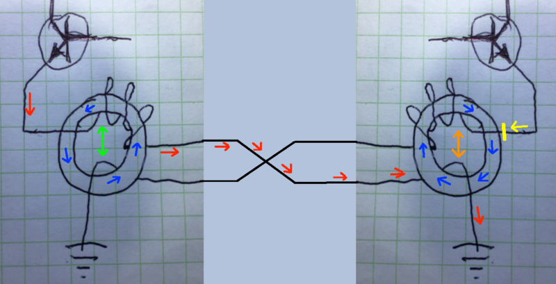
Current flow on the red path through the left core meets low impedance,
as the core is already magnetised in the favourable polarity.

Transformer coupling across the green arrow is very weak because the left core was
already close to saturation, and there is little room for a change in flux density.

Current flow on the red path through the right core turns the opposite direction through
the core, and also meets low impedance because the core is also set in the opposite direction.

Transformer coupling across the orange arrow is also very weak for the same reason as
in the left core.

Current flow on the yellow path meets high impedance for more than one reason.
The right core is set so that current on the yellow path will try to reverse the magnetic
polarity, and the right core transformer turns ratio presents higher impedance for
current flow on the yellow path, especially while current is flowing on the red path,
pushing in the opposite direction.
Cheers, Brek.


Share me

Digg  Facebook  SlashDot  Delicious  Technorati  Twitter  Google  Yahoo
Smf