Author Topic: High Voltage 10-100MHz Differential Probe Investigated  (Read 66087 times)

0 Members and 1 Guest are viewing this topic.

Offline MechatrommerTopic starter

  • Super Contributor
  • ***
  • Posts: 11622
  • Country: my
  • reassessing directives...
High Voltage 10-100MHz Differential Probe Investigated
« on: May 28, 2012, 05:07:43 am »
Original Spec:
a) ±330V input (using simple resistors voltage divider)
b) 100MHz bandwidth (using proper opamps)
c) simple input protection using clamp/limiting diodes
d) built-in fixed attenuator (so not to hassle around with input and many attenuators)
e) from jellybeans components (%1 resistor etc, need 0.01% matching? use trimpots!)
thats all as far i remember

Current Spec:
1) ±500V input (still using simple resistors voltage divider, because its... "simple")
2) 20-100MHz (it depends on my "engineuering competency" up to this point)
3) still with simple input protection using clamp/limiting diodes (the study has not been furthered to this stage, "good enough" is assumed)
4) noise:
   50-100mVpp (effective noise at 1/100X setting), currently at ~200mVpp achieved
   5-10mVpp (effective noise at 1/10X setting), currently at ~20mVpp achieved
   0.5-1mVpp (effective noise at 1X setting), currently at 2mVpp achieved
5) CMRR:
   >60dB @ 1MHz and slower freq (preferably 90dB and more but... thats my tools' limitation i believe) currently at 45dB @ 1MHz, i believe i can reach nearer to opamp's CMRR limit.
   ~40dB @ 10MHz (currently at 25dB and not sure at higher freq, as mystical things creeped in)
6) psu from unregulated bipolar ±20V, regulated to ±12V
thats it! i think for now...

note: the input can "easily" be upgraded to ±1KV but for later...

as i said, this one is not finalized, and infact i still continue to refine this esp in several areas:
1) input attenuation, matching and freq compensation.
2) bandwidth specification (combo'ed with above)
3) CMRR (opamp selection)
4) noise level (opamp selection, combo'ed with (2))

(msg edited)
« Last Edit: September 04, 2012, 12:39:57 pm by Mechatrommer »
Nature: Evolution and the Illusion of Randomness (Stephen L. Talbott): Its now indisputable that... organisms “expertise” contextualizes its genome, and its nonsense to say that these powers are under the control of the genome being contextualized - Barbara McClintock
 

Offline MechatrommerTopic starter

  • Super Contributor
  • ***
  • Posts: 11622
  • Country: my
  • reassessing directives...
Re: OSHW DIY 1KV 100MHz Differential Probe (Dilemma vs. Hope)
« Reply #1 on: May 28, 2012, 05:15:58 am »
1st pardon me for my non-standard way of explaining things, i'm no ee "engineuers" and i "aint no A?tium", and i think i hate to redraw, this typing alone is a tremendous effort i try to achieve. so i just post what i have done, if its not clear, please ask. i drew things in diptrace (non-standard my own library symbols) in "dog's breakfast sphagetty way" but i hope it will be self explanatory with its marking (i tried to be as standard as i can :() i also have tina-spice schematics, but i think those are from older version, i didnt update/redraw in latest revision, too tired with all the changes. i'll post when i see fits. and also pardon me for black style background, my eyes work better with that in diptrace.

first we start with the "well known" 3 opamps instrumentation amplifier, here (wiki image) for those who didnt know...

there's 2 opamps type, why 3? because its matched high impedance noninverting input, thats good, so thats the choosen one, right in the first place. the latest version will use gain 2X ins-amp (originally gain 10X)

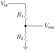
and then, no opamp can take ±500V mains line direct, not even any high speed bjt/fet i'm aware of (only big type ones), even if there is, designing raw discreete transistors will complicate things astronomically for me, so i stayed with opamps as the simplest building block. so in order the opamp to eat the ±500V, it needs attenuator, resistors voltage divider is the only thing i can understand easily for now. again from wiki...


since we are dealing with high frequency input, some compensation using capacitors will be needed, something like this, in combo with the above...

(i'll use 1/100X divider in the latest revision, combo'ed with gain 2X in ins-amp, resulting in 1/50X to the scope input unterminated, and 1/100X if terminated, beauty! 8))

thats it! simple isnt it? the rest is ofcourse... psu, and the supporting components (bypass caps, compensation networks, bnc or sma connectors and a bunch of coaxes and wires and cheapo smd hooks etc... and "very" good pcb layout to run it with, never excel with that yet) and of course, some tweaking with generator,scope and the circuit.

so all those basic things can be summarized in block diagram as below (diptrace)...

input=attenuator or voltage divider.
cmrr+differential = the mentioned 3 opamp ins-amp, i divided them into 2 parts
power = is power supply.
whats not shown is the output which is just a simple 50ohm terminated coax cable. and the image shown is for ver H above, but its been like that from the early stage, no change on this part/concept.

now lets take a look one by one at the block. we start first at psu, its nothing just a standard datasheet circuit using bipolar LM317/LM337 (jellybeans?) regulator. its the latest rev H. in earlier version, the regulator resides in the wallwart (or my bench psu), but now its integrated in the probe (due to some long story reason). here (diptrace ver H)...

the device will take unregulated bipolar supply from wallwart through LA_BATT tab there, regulated by the LM317/337 and feed the circuit (the other blocks) through the V+,gnd,V- connector there, ±12V supply to circuit, the opamps will be expected to output ±10V to the scope. simple! can be overclocked to ±15V supply to circuit if you wish for ±600V input, beauty! 8)

and then the next block is the input rev G. here...

the important components are Ri+, Rd+ and series trimpot for matching and its negative counterparts just a mirror of them (divider is 1Mohm and 10Kohm, ie 1/100X), i leave the compensation part for you (Cci, Cod, Cadj etc), i provided more compensation network in case i need it.

in the latest input rev H, theres 3 network, LF compensation, MF and high freq (HF), probably i'm not going to need all, just in case. here's the half-completed rev H input (for 1X setting). 100Kohm input impedance (Rt+, Rt-), too low for ±5V input probing? yea, talking about the wrong (not so good) opamp buffer here (THS3092 1Mohm input). larger than 100Kohm terminator/pull down will output garbage nasty offset at the output. even with this 100Kohm, but thanks to the "drifty" null offset circuit (below) 8) :P


next... cmrr+differential block. they form the 3 opamps ins-amp config mentioned above, with supporting circuit, compensation, null offset from zeners, trimpot and buffer to zero the output offset. this should be pretty simple. i leave the detailed explanantion to you to avoid "boringness", any questions just ask ;) ins-amp buffer is 2x opamp THS3092, and the differential opamp is THS3091. currently achieved BW is 20-50MHz (due to not so good input matching and compensation, reflections and other mystical things) so quite a waste for 100++MHz BW opamps. re-selection will be in order if required.


to the 4th post... the result...
« Last Edit: May 28, 2012, 05:19:22 am by Mechatrommer »
Nature: Evolution and the Illusion of Randomness (Stephen L. Talbott): Its now indisputable that... organisms “expertise” contextualizes its genome, and its nonsense to say that these powers are under the control of the genome being contextualized - Barbara McClintock
 
The following users thanked this post: BurnedResistor

Offline MechatrommerTopic starter

  • Super Contributor
  • ***
  • Posts: 11622
  • Country: my
  • reassessing directives...
Re: OSHW DIY 1KV 100MHz Differential Probe (Dilemma vs. Hope)
« Reply #2 on: May 28, 2012, 05:27:27 am »
the following is the latest "real circuit" ver.G thats what i can show you the result with (currently working on rev H, no real circuit or pcb layout yet).

1) the "not so good" diy circuit.


2) some probing test i made earlier on offline cheapo smps circuit with rev F circuit. the probing is between the hi-freq transformer primary high side leads. the low side? there's mosfet switching going on, but not shown/care.


3) the DUT to probe test with. i will plan for bigger circuit when i finish this project (if i manage to get around it), namely using PC PSU transformer, which with its small size capable of supplying 12V 15A, which is not available in 50/60Hz linear supply transformer, at that lightweightness, not even very close.


4) the noise floor of the device if probe input disconnected (150-250mVpp) at 100X scope attenuation setting, too bad (a shame?) non engineering achievement :P from rev.F (blue trace)


5) last but not least, i used to enjoy looking at differential signal between my FG output (sine) and its synch output (square). at 3-6Vpp, the output signal looks cleaner, acceptable and nice at the 100X setting, so i truely believe there is a hope since there is a "visible" proof :P. yellow = fg output, blue = diff.probe output (sine-square)


to the 5th post... the conclusion...
« Last Edit: May 28, 2012, 05:49:58 am by Mechatrommer »
Nature: Evolution and the Illusion of Randomness (Stephen L. Talbott): Its now indisputable that... organisms “expertise” contextualizes its genome, and its nonsense to say that these powers are under the control of the genome being contextualized - Barbara McClintock
 
The following users thanked this post: boB

Offline MechatrommerTopic starter

  • Super Contributor
  • ***
  • Posts: 11622
  • Country: my
  • reassessing directives...
Re: OSHW DIY 1KV 100MHz Differential Probe (Dilemma vs. Hope)
« Reply #3 on: May 28, 2012, 05:28:01 am »
so what do you think guys? is this workable to you? (it is for me ???) is it really worth it? what other explanations should i include here? constructive comments and better suggestions are very welcomed. since i made this open, i'm hoping and look forward to working together as community so we can build a better future and "save the world" :P. and more importantly... "redefining industry" at hobby level, i hope thats not so offensive a statement for some people :P otherwise... there is not much point of making this open isnt it? until then.
Nature: Evolution and the Illusion of Randomness (Stephen L. Talbott): Its now indisputable that... organisms “expertise” contextualizes its genome, and its nonsense to say that these powers are under the control of the genome being contextualized - Barbara McClintock
 

Offline T4P

  • Super Contributor
  • ***
  • Posts: 3697
  • Country: sg
    • T4P
Re: OSHW DIY 1KV 100MHz Differential Probe (Dilemma vs. Hope)
« Reply #4 on: May 28, 2012, 04:41:59 pm »
so what do you think guys? is this workable to you? (it is for me ???) is it really worth it? what other explanations should i include here? constructive comments and better suggestions are very welcomed. since i made this open, i'm hoping and look forward to working together as community so we can build a better future and "save the world" :P. and more importantly... "redefining industry" at hobby level, i hope thats not so offensive a statement for some people :P otherwise... there is not much point of making this open isnt it? until then.

It's really useful, mate. Keep on going, i'll give you the morale boost  ;D
 
The following users thanked this post: boB

Offline NiHaoMike

  • Super Contributor
  • ***
  • Posts: 9007
  • Country: us
  • "Don't turn it on - Take it apart!"
    • Facebook Page
Re: OSHW DIY 1KV 100MHz Differential Probe (Dilemma vs. Hope)
« Reply #5 on: May 28, 2012, 05:57:06 pm »
You can probably get a large improvement in CMRR by powering it from batteries and using RF modulated isolation.
Cryptocurrency has taught me to love math and at the same time be baffled by it.

Cryptocurrency lesson 0: Altcoins and Bitcoin are not the same thing.
 

Offline NiHaoMike

  • Super Contributor
  • ***
  • Posts: 9007
  • Country: us
  • "Don't turn it on - Take it apart!"
    • Facebook Page
Re: OSHW DIY 1KV 100MHz Differential Probe (Dilemma vs. Hope)
« Reply #6 on: May 28, 2012, 08:42:14 pm »
Quote
using RF modulated isolation
whats that animal? example please? thanks for advice. i did try with batteries earlier, i cant see any substantial difference.
You take the signal from the amplifier, modulate a RF carrier with it, send the signal across a RF transformer, then demodulate the RF.
Cryptocurrency has taught me to love math and at the same time be baffled by it.

Cryptocurrency lesson 0: Altcoins and Bitcoin are not the same thing.
 

Offline MechatrommerTopic starter

  • Super Contributor
  • ***
  • Posts: 11622
  • Country: my
  • reassessing directives...
Re: OSHW DIY 1KV 100MHz Differential Probe (Dilemma vs. Hope)
« Reply #7 on: May 30, 2012, 05:57:08 am »
i think i'll end this masaccre at ver 1H (rev2) for now. i've ammended input front end, separated attenuator decision is cancelled, back to built-in. so here's the latest ver.1H (rev2), the rest are the same...


pcb layout, top with silk...


pcb layout, top without silk...


pcb layout, bottom (mirrored for easier tracing with top layer)...


pcb layout, top 3d...


pcb layout, bottom 3d (mirrored for easier tracing with top layer)...


pcb layout, top 3d explained...


the pcb size (and mounting holes) is fixed based on project enclosure that i have. i hope i'll hear some CnC before making this into reality (esp on high freq components placement and signal path/coupling)...

edit: via stitches not shown yet, but solved. no problem there :P
« Last Edit: May 30, 2012, 06:48:03 am by Mechatrommer »
Nature: Evolution and the Illusion of Randomness (Stephen L. Talbott): Its now indisputable that... organisms “expertise” contextualizes its genome, and its nonsense to say that these powers are under the control of the genome being contextualized - Barbara McClintock
 

Offline T4P

  • Super Contributor
  • ***
  • Posts: 3697
  • Country: sg
    • T4P
Re: OSHW DIY 1KV 100MHz Differential Probe (Dilemma vs. Hope)
« Reply #8 on: May 30, 2012, 08:49:48 am »
That's really very nice. Good job mecha!
 

Offline Fox

  • Regular Contributor
  • *
  • Posts: 54
  • Country: de
  • Electronics Engineer
Re: OSHW DIY 1KV 100MHz Differential Probe (Dilemma vs. Hope)
« Reply #9 on: May 30, 2012, 09:04:42 pm »
Very nice project.

To improve  the cmrr you should use a single Instrumentation opamp not three opamp in separate packages, search for Instrumentation amps or ADC Driver opamps.
The reason for not so good cmrr with the three opamp version is, that the cmrr is strongly dependent from the ratio of your resistors (precision and temperature wise).
For the best cmrr, the input dividers should be as stable as you can get them (thick film hybrid resistors for example).

Here al link to the "Op Amp Applications Handbook" from Analog Devices, i highly recommend it and it's free.
http://www.analog.com/library/analogDialogue/archives/39-05/op_amp_applications_handbook.html


The Gainbandwithproduct of your Opamp should be much higher than 200MHz ( 100MHZ signal Bandwith, Gain of 2) i suggest at least 350MHz.
For your input divider something like this should be suitable.
http://giciman.com/notes/7.shtml
A closed Switch should have zero Ohms or less!
 

Offline MechatrommerTopic starter

  • Super Contributor
  • ***
  • Posts: 11622
  • Country: my
  • reassessing directives...
Re: OSHW DIY 1KV 100MHz Differential Probe (Dilemma vs. Hope)
« Reply #10 on: May 31, 2012, 05:32:32 am »
thanks for the advice fox. i think i have many (including the one you linked) "generic" opamp application app-note already.

Quote
To improve  the cmrr you should use a single Instrumentation opamp not three opamp in separate packages, search for Instrumentation amps
i thought i have been an "accomplished" at this (bolded quote), the problem is, premade ins-amp will go max to few MHz (1-2MHz iirc), but please enlighten me! as my net is very slow i cannot search the whole world very quickly.

Quote
or ADC Driver opamps
talk about overkill app here? afaik, "digital" is not needed in this simple application. pls prove me wrong ;)

Quote
that the cmrr is strongly dependent from the ratio of your resistors (precision and temperature wise).
For the best cmrr, the input dividers should be as stable as you can get them (thick film hybrid resistors for example).
200% agree. as for now, i just use cheapo resistors and trimmers to match (acceptable result! considering those crappies ;), but alas drifty maybe due to high tempco). if i got the circuit right, its just a matter of replacing with high quality components.

Quote
The Gainbandwithproduct of your Opamp should be much higher than 200MHz ( 100MHZ signal Bandwith, Gain of 2) i suggest at least 350MHz.
for voltage feedback opamp, i agree with you. i have current feedback opamp here (THS3092) that will be happy doing 100MHz at gain of 10 (no vfb GBW/gain law here). and/but i'm thinking to replace it with LM6172 vfb (GBW 100MHz) in my stock, at gain of 2, i think its good for 20-30MHz, i think i'll lower the spec from 100 to 20MHz, since mystical things like reflection is enough to make my head scratching (with my limited tools). i'll finalized the circuit/pcb with 20-30MHz spec first, and in case i need to increase the BW, it just a matter of replacing the opamp with higher one or cfb/cfa.

for the 3 discreete opamps ins-amp setup:
-the 2 input buffer (with gain) opamps... utmost importance is lowest noise, high imput impedance and thats it!
-for the difference (3rd) opamp... utmost importance is, highest CMRR and thats it! (so even my best resistors matching, it will not be limited by lower CMRR opamp)

of course all of them must be capable of the said BW and slewrate (2pi.BW.V) 7-10Volt and supply from the psu, which as for now, it ±12V, but i will be glad to move down to ±5V if there's better combo (which i'm not yet figure out) for the above mentioned opamps requirement.

Quote
For your input divider something like this should be suitable.
http://giciman.com/notes/7.shtml
good read! thanks!
Nature: Evolution and the Illusion of Randomness (Stephen L. Talbott): Its now indisputable that... organisms “expertise” contextualizes its genome, and its nonsense to say that these powers are under the control of the genome being contextualized - Barbara McClintock
 

Offline SeanB

  • Super Contributor
  • ***
  • Posts: 16276
  • Country: za
Re: High Voltage 10-100MHz Differential Probe (Dilemma vs. Hope, OSHW?)
« Reply #11 on: May 31, 2012, 01:21:47 pm »
For some nice old design notes try this old Tek plugin...

http://w140.com/tekwiki/wiki/5A19

I like it, nice and easy to use, in the scope of course........ That nice good old Tek build and design.
 

Offline MechatrommerTopic starter

  • Super Contributor
  • ***
  • Posts: 11622
  • Country: my
  • reassessing directives...
Re: High Voltage 10-100MHz Differential Probe (Dilemma vs. Hope, OSHW?)
« Reply #12 on: May 31, 2012, 09:34:22 pm »
thanks sean! good reference, frontend divider and compensation, and but err... discrete transistors design ::) ... thanks.
Nature: Evolution and the Illusion of Randomness (Stephen L. Talbott): Its now indisputable that... organisms “expertise” contextualizes its genome, and its nonsense to say that these powers are under the control of the genome being contextualized - Barbara McClintock
 

Offline SeanB

  • Super Contributor
  • ***
  • Posts: 16276
  • Country: za
Re: High Voltage 10-100MHz Differential Probe (Dilemma vs. Hope, OSHW?)
« Reply #13 on: June 01, 2012, 05:07:30 am »
This was designed in the days when Bob Peace was still young, and was busy working the kinks out of the 741 and it's relatives. The scope design is old, dating from the early 1960's.
 

Offline MechatrommerTopic starter

  • Super Contributor
  • ***
  • Posts: 11622
  • Country: my
  • reassessing directives...
Re: High Voltage 10-100MHz Differential Probe (Dilemma vs. Hope, OSHW?)
« Reply #14 on: June 01, 2012, 07:05:32 pm »
yes old but i guess resistor never die :P
Nature: Evolution and the Illusion of Randomness (Stephen L. Talbott): Its now indisputable that... organisms “expertise” contextualizes its genome, and its nonsense to say that these powers are under the control of the genome being contextualized - Barbara McClintock
 

alm

  • Guest
Re: High Voltage 10-100MHz Differential Probe (Dilemma vs. Hope, OSHW?)
« Reply #15 on: June 01, 2012, 09:06:17 pm »
I'm not aware of any published schematics for recent diff probe designs. The most recent I'm aware of is in the Tek P6046 service manual (designed in late 60s, produced until late 90s, something like 10k:1 CMRR at 1MHz), but this is also a discrete transistor design. Nobody in their right mind would design a circuit like this with discrete transistors these days, controlling thermal offset drift is much easier when they are on the same die. Most of the relatively low bandwidth (<= 200 MHz or so) HV diff probes use video line drivers as amplifier.

CMRR at 1kV might also be a problem. Most resistors have a voltage coefficient. Even if this effect is less than 1% at 1kV of common mode voltage, it will reduce the CMRR to a little over 40 dB. Same applies to mismatches and changes in the compensation capacitors.
« Last Edit: August 20, 2013, 03:20:12 pm by alm »
 

Offline MechatrommerTopic starter

  • Super Contributor
  • ***
  • Posts: 11622
  • Country: my
  • reassessing directives...
Re: High Voltage 10-100MHz Differential Probe (Dilemma vs. Hope, OSHW?)
« Reply #16 on: June 01, 2012, 10:23:30 pm »
Quote
10k:1 CMRR
yup that is... pretty much impossible for me (to do or to measure).
Quote
CMRR at 1kV might also be a problem. Most resistors have a voltage coefficient. Even if this effect is less than 1% at 1kV of common mode voltage, it will reduce the CMRR to a little over 40 dB. Same applies to mismatches and changes in the compensation capacitors.
i believe the keyword for that is "component quality", or maybe some fancy technique, like tempco cancellation dave talked about (for capacitor) i still having difficulty finding sources for -ve and +ve tempco resistor and its characteristic stuffs. so i decided i just work it out with jellybean components. thats one of the limitation here :(
Nature: Evolution and the Illusion of Randomness (Stephen L. Talbott): Its now indisputable that... organisms “expertise” contextualizes its genome, and its nonsense to say that these powers are under the control of the genome being contextualized - Barbara McClintock
 

Offline hlavac

  • Frequent Contributor
  • **
  • Posts: 536
  • Country: cz
Re: High Voltage 10-100MHz Differential Probe (Dilemma vs. Hope, OSHW?)
« Reply #17 on: June 01, 2012, 11:27:04 pm »
I'm a bit worried about the safety of this. Track clearances on the high voltage inputs - I would expect a minimum of 5mm required clearance to be safe, probably more (there are standards for that).

Also common resistors have a breakdown voltage across them of around 250V, you would need to put multiple of them in series or use some special high voltage ones...
Good enough is the enemy of the best.
 

Offline MechatrommerTopic starter

  • Super Contributor
  • ***
  • Posts: 11622
  • Country: my
  • reassessing directives...
Re: High Voltage 10-100MHz Differential Probe (Dilemma vs. Hope, OSHW?)
« Reply #18 on: June 02, 2012, 07:32:43 am »
yes i'm aware of that. and i dont have access to the "exact" standard sigh (i aint engineuer). i did experiment with multiple series input resistor (the through hole one), compensation and things, my earlier pcb got more clearance, and later got rid of that phobialism (lesser clearance and only one "power" resistor/divider). thats why i tried to limit it to ±500V (1KV differential), it means at any instant, each probe will sense no more than 500V magnitude, i'm not going to venture in 1KV "magnitude" risking dialectric breakdown. and "THAT" 500V magnitude is considered "MAXED", ie things like short spike and transient. it doent mean you have to probe steady 500V. from my wattage calculation, probing steady at 500V is using 100% of the resistor wattage capacity (0.25W), ie it will get hot and thats not good. probing at (hobby level) 110-240Vrms will use less or equal to quarter of the capacity iirc (experiment showed no heat build up so far, not sure about resistance value and drift). yes, it will come down to component quality (beside the arrangement and standard).

anyway, please prove me wrong and i'll be happy if i can get the link to the "bylaw standard". and i agree, this thing need to be highlighted and we should aware of, thanks for highlighting. if i have the standard, i'll be happy to ammend my pcb (if i got the room) but since the intention is at hobby level (no serious high voltage high power stuff), so yeah as sad as it is, standard is pretty much at the bottom of my list right now. even the sma input connectors i used will not up to that 5mm clearance compliance (if it is). its not that i want to ignore it, but the thing is i would like to make it simpler (irreducibly complex) and concentrate on signal path (at greater than 10-20MHz, things got nasty without coax/sma connection) so the word dilemma or compromise is the term.
Nature: Evolution and the Illusion of Randomness (Stephen L. Talbott): Its now indisputable that... organisms “expertise” contextualizes its genome, and its nonsense to say that these powers are under the control of the genome being contextualized - Barbara McClintock
 

Offline T4P

  • Super Contributor
  • ***
  • Posts: 3697
  • Country: sg
    • T4P
Re: High Voltage 10-100MHz Differential Probe (Dilemma vs. Hope, OSHW?)
« Reply #19 on: June 02, 2012, 09:02:33 am »
Ain't SMA pretty small compared to coax ?
 

Offline MechatrommerTopic starter

  • Super Contributor
  • ***
  • Posts: 11622
  • Country: my
  • reassessing directives...
Re: High Voltage 10-100MHz Differential Probe (Dilemma vs. Hope, OSHW?)
« Reply #20 on: June 02, 2012, 10:53:46 am »
Ain't SMA pretty small compared to coax ?
SMA is a "connector" / "adapter", coax is a "cable". there's big coax small coax, each with its own characteristic impedance 50ohm 75ohm and "what not". connector have SMA, BNC, N and "what have you". you dont put big coax into small connector vice versa. be carefull when buying SMA, there's SMA to RG718, there's SMA to RG58, different! same with BNC. go search wiki, there's many type than i (even wiki) can list.
Nature: Evolution and the Illusion of Randomness (Stephen L. Talbott): Its now indisputable that... organisms “expertise” contextualizes its genome, and its nonsense to say that these powers are under the control of the genome being contextualized - Barbara McClintock
 

Offline T4P

  • Super Contributor
  • ***
  • Posts: 3697
  • Country: sg
    • T4P
Re: High Voltage 10-100MHz Differential Probe (Dilemma vs. Hope, OSHW?)
« Reply #21 on: June 02, 2012, 11:13:34 am »
Ain't SMA pretty small compared to coax ?
SMA is a "connector" / "adapter", coax is a "cable". there's big coax small coax, each with its own characteristic impedance 50ohm 75ohm and "what not". connector have SMA, BNC, N and "what have you". you dont put big coax into small connector vice versa. be carefull when buying SMA, there's SMA to RG718, there's SMA to RG58, different! same with BNC. go search wiki, there's many type than i (even wiki) can list.

Oops i mean BNC, sorry about that
 

Offline hlavac

  • Frequent Contributor
  • **
  • Posts: 536
  • Country: cz
Re: High Voltage 10-100MHz Differential Probe (Dilemma vs. Hope, OSHW?)
« Reply #22 on: June 02, 2012, 01:12:44 pm »
According to this, for 500V you need absolute minimum of 2.5mm, preferably 3mm of clearance.
Good enough is the enemy of the best.
 

Offline MechatrommerTopic starter

  • Super Contributor
  • ***
  • Posts: 11622
  • Country: my
  • reassessing directives...
Re: High Voltage 10-100MHz Differential Probe (Dilemma vs. Hope, OSHW?)
« Reply #23 on: June 02, 2012, 07:42:04 pm »
According to this, for 500V you need absolute minimum of 2.5mm, preferably 3mm of clearance.
great! thanks alot pal! will make it as reference.
Nature: Evolution and the Illusion of Randomness (Stephen L. Talbott): Its now indisputable that... organisms “expertise” contextualizes its genome, and its nonsense to say that these powers are under the control of the genome being contextualized - Barbara McClintock
 

Offline Lightages

  • Supporter
  • ****
  • Posts: 4314
  • Country: ca
  • Canadian po
Re: High Voltage 10-100MHz Differential Probe (Dilemma vs. Hope, OSHW?)
« Reply #24 on: June 02, 2012, 08:22:16 pm »
I like this project Mechatrommer. I think most people would like a differential probe for many things if they weren't so damned expensive. As you see, one of the reasons they might be so expensive is the many considerations in design and safety for a commercial product. If you do continue to develop this, I would be happy to buy a kit or circuit boards from you so you can profit from your work.  Please continue....


Share me

Digg  Facebook  SlashDot  Delicious  Technorati  Twitter  Google  Yahoo
Smf