Author Topic: PWM power PCB for TEC cooling  (Read 3645 times)

0 Members and 1 Guest are viewing this topic.

Offline jedi95Topic starter

  • Newbie
  • Posts: 3
  • Country: us
PWM power PCB for TEC cooling
« on: November 25, 2017, 10:23:53 am »
I'm working on a temperature control/power PCB for a TEC based water chiller. This will be used in a high end PC for CPU cooling.

The cooling system looks like this:
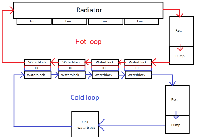

The requirements are:
1. The power input used for the TECs is 12V from a PC power supply (using PCI-E 8-pin connectors)
2. The board must be able to output 12V to the TECs at full power.
3. No electromechanical relays.
4. TEC cooling power controlled based on coolant temp, and current dew point of the ambient air.
5. Software monitoring and control of the system.

I had 3 basic options for the temperature control:
1. Thermostat-like on/off
2. PWM
3. Voltage-based

#1 is the simplest to implement, but it will cause increased thermal cycling of the TECs.

#2 is straightforward, but I'm worried about what PWM switching of a large load will do to a PC power supply.

#3 is the most complex, and I don't see a good way to get a voltage regulator with maximum voltage equal to the input voltage.


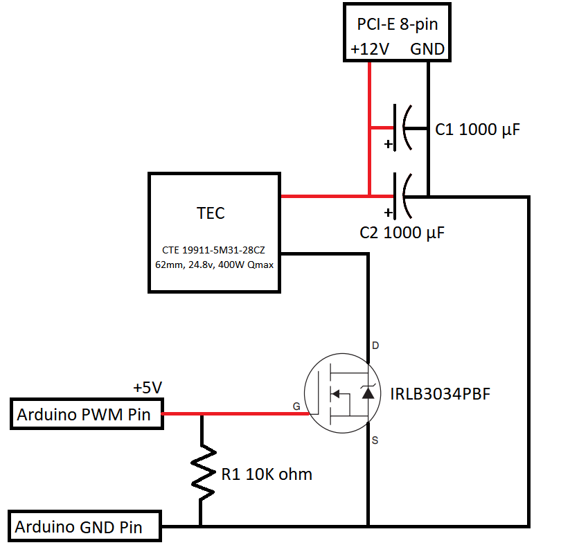
I decided to go with the PWM based design. The circuit I'm using looks like this:

Relevant datasheets:
https://www.infineon.com/dgdl/irlb3034pbf.pdf?fileId=5546d462533600a40153566027b22585
https://customthermoelectric.com/media/wysiwyg/TEC_spec_sheets/19911-5P31-28CZ_spec_sht.pdf

The 10K resistor is to pull down the MOSFET gate if the Arduino-based control device is not powered. The 2 capacitors are for decoupling. The TEC will pull roughly 12.5A when operating at 12V, or 150W. I have built a prototype of this circuit and it does appear to work correctly. The power consumption scales ~linearly with the PWM duty cycle, and the MOSFET doesn't seem to heat up much.

Circuit questions:
1. Is my choice of decoupling capacitor size sufficient? If not, how would I calculate the correct size?
2. Is there a certain PWM frequency that would be better? It must be at least 1KHz per the TEC manufacturer, but outside of that I don't know what would be best.

If there are no major flaws in the basic circuit, the next part is getting it onto a PCB. I'm new to PCB design, but I was able to create this:
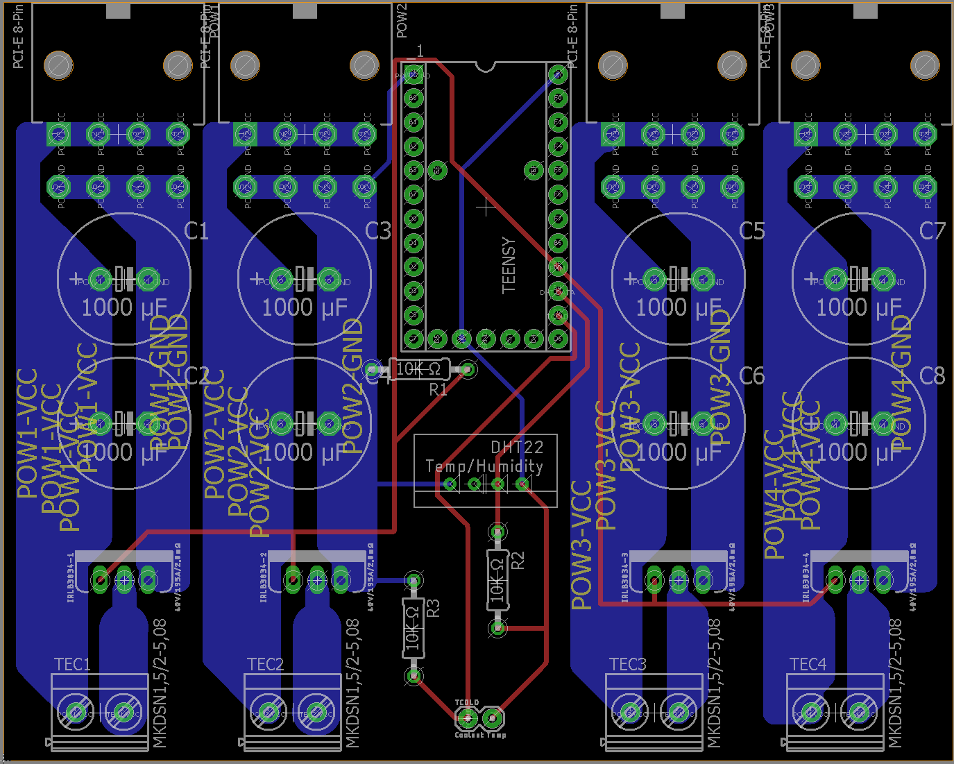

It's a 2-layer design. I'm going to use a Teensy 2.0 to control everything:
https://www.pjrc.com/store/teensy_pins.html

That version has header pins, which I plan to through-hole solder onto the larger power PCB. This simplifies the board because I will be able to solder all the components myself.

My main concern is the trace width for the high current nets. I used the calculator here:
http://www.4pcb.com/trace-width-calculator.html

According to that, I need 96.3 mil trace width for 12.5A @ 10C rise using 4oz copper. I used 100 mil minimum trace width for them in the design above, but attempted to make them much wider where possible.

PCB questions:
1. Am I handling the high current traces correctly? If not, what do I need to change?
2. Is there anything else that appears to be wrong? This is my first PCB so I may have missed something.

Thanks for looking.
« Last Edit: November 25, 2017, 10:27:18 am by jedi95 »
 

Offline Siwastaja

  • Super Contributor
  • ***
  • Posts: 8172
  • Country: fi
Re: PWM power PCB for TEC cooling
« Reply #1 on: November 25, 2017, 10:36:23 am »
PWMing Peltier elements is definitely not recommended, for two reasons:

1) They crack even more easily caused by high-frequency vibration caused by the fast edges, and/or thermal cycling if low fundamental frequencies are used.
2) Because the already poor efficiency of the peltier goes down with the current, with PWM control, you are always running at the lowest worst-case efficiency (i.e., what you get with the full voltage), even with partial power. With proper smooth voltage, the efficiency is only that bad when you actually need to use the full power, but somewhat better at partial power.

Your PC supply is fine with the ripple, but the Peltiers are not.

You can do an unregulated buck by adding a freewheeling diode and LC filtration network at the output. This might be an acceptable solution. You don't need to make it perfect; I'm sure some triangle-shape current ripple is not a huge problem, compared to square wave edges between 0% and 100% current.

Last, just saying, Peltiers totally suck in that kind of application. You need hugely powerful cooling with well-designed thermal coupling for the hot loop; otherwise, the Peltiers do more harm than good. Even if you do everything right, you are only getting about 20 degC extra temperature drop, and with abysmally horrible efficiency. Definitely consider a real refrigerant-based system; with that, you can easily get 40-50 degC temperature drop with one third wasted energy, and a smaller system.

Peltiers are, in fact, so damn bad that you'd most likely simply want to run them continuously at as much power as possible - this typically means running at about 3/4 the rated power. When less heat is generated in the CPU, they just cool down a bit more and kind of self-regulate. Efficiency is bad without control, but it's super bad anyway with Peltiers, so I wouldn't care.

Re: PCB: include a series gate resistor. The MOSFET is big; charging the gate may cause issues with the IO port or MCU reliability since you are exceeding absolute maximum ratings severely in repetitive pulses. Something like 47R is a good compromise to bring the current down to safe level without slowing down the gate drive too much. You are likely going to have quite some switching loss in the FETs with switching this slow, but OTOH, it can save your Peltiers from cracking too soon. And if you cool down the FETs, then you only have an efficiency issue, which you have anyway having 1.6kW unnecessary heater going on all the time.

BTW, you need a radiator specified to about 100-200kW, so something from a car, preferably a sports car or a truck, would work. Why? This is because the Peltiers can only provide any meaningful cooling power when the temperature difference is minimal (like 20-30 degC). Now, if you actually want to cool your "cool side" down by even 20 degC, you have 0 degC left for the hot side to heat up! So you need a perfect coupling to a perfect water cooling block, with that connected to an infinite radiator!
« Last Edit: November 25, 2017, 10:50:23 am by Siwastaja »
 

Offline Twoflower

  • Frequent Contributor
  • **
  • Posts: 737
  • Country: de
Re: PWM power PCB for TEC cooling
« Reply #2 on: November 25, 2017, 10:51:55 am »
Haven't checked every detail. But found two things:
1. You're operating the FETs very close to or even exceed the border of the SOA.
2. The GND of the four channels should be connected. Otherwise it could end bad for the FETs of the other 3 channels (ground-loop).
3. A flyback diode across the Peltiers won't hurt and will reduce the chance some parasitic inductance causing trouble.

But as already mentioned: Peltiers are not very efficient. And you got some feedback regarding the operating these.


Edit: Added point 3
« Last Edit: November 25, 2017, 10:54:37 am by Twoflower »
 

Offline jedi95Topic starter

  • Newbie
  • Posts: 3
  • Country: us
Re: PWM power PCB for TEC cooling
« Reply #3 on: November 25, 2017, 01:40:28 pm »
A few things to clarify:
1. I'm running the TECs at just under half their rated voltage. (Vmax of 24.8v, actual 12v) This gives me acceptable efficiency. (150W power consumption to remove 100W of heat at 30C delta - per TEC)
2. I understand that using PWM means losing the benefit of higher coefficient of performance that I could get with voltage based control.
3. I have considered using something like an aquarium chiller instead of TECs, but the compressor noise would be an issue.
4. Having no control won't work. The difference between CPU idle and load power consumption is large enough such that running the TECs at 100% would cause condensation or the coolant to freeze.

With that out of the way,

PWMing Peltier elements is definitely not recommended, for two reasons:

1) They crack even more easily caused by high-frequency vibration caused by the fast edges, and/or thermal cycling if low fundamental frequencies are used.
2) Because the already poor efficiency of the peltier goes down with the current, with PWM control, you are always running at the lowest worst-case efficiency (i.e., what you get with the full voltage), even with partial power. With proper smooth voltage, the efficiency is only that bad when you actually need to use the full power, but somewhat better at partial power.

Your PC supply is fine with the ripple, but the Peltiers are not.

You can do an unregulated buck by adding a freewheeling diode and LC filtration network at the output. This might be an acceptable solution. You don't need to make it perfect; I'm sure some triangle-shape current ripple is not a huge problem, compared to square wave edges between 0% and 100% current.

Last, just saying, Peltiers totally suck in that kind of application. You need hugely powerful cooling with well-designed thermal coupling for the hot loop; otherwise, the Peltiers do more harm than good. Even if you do everything right, you are only getting about 20 degC extra temperature drop, and with abysmally horrible efficiency. Definitely consider a real refrigerant-based system; with that, you can easily get 40-50 degC temperature drop with one third wasted energy, and a smaller system.

Peltiers are, in fact, so damn bad that you'd most likely simply want to run them continuously at as much power as possible - this typically means running at about 3/4 the rated power. When less heat is generated in the CPU, they just cool down a bit more and kind of self-regulate. Efficiency is bad without control, but it's super bad anyway with Peltiers, so I wouldn't care.

Re: PCB: include a series gate resistor. The MOSFET is big; charging the gate may cause issues with the IO port or MCU reliability since you are exceeding absolute maximum ratings severely in repetitive pulses. Something like 47R is a good compromise to bring the current down to safe level without slowing down the gate drive too much. You are likely going to have quite some switching loss in the FETs with switching this slow, but OTOH, it can save your Peltiers from cracking too soon. And if you cool down the FETs, then you only have an efficiency issue, which you have anyway having 1.6kW unnecessary heater going on all the time.

BTW, you need a radiator specified to about 100-200kW, so something from a car would work.

-Good point with the series gate resistor.
-The technical contact at the TEC manufacturer told me that PWM control was fine, provided that Vmax is not exceeded and the switching frequency is high enough (>=1KHz). Do you have a source for high frequency PWM causing damage to TECs?

Haven't checked every detail. But found two things:
1. You're operating the FETs very close to or even exceed the border of the SOA.
2. The GND of the four channels should be connected. Otherwise it could end bad for the FETs of the other 3 channels (ground-loop).
3. A flyback diode across the Peltiers won't hurt and will reduce the chance some parasitic inductance causing trouble.

But as already mentioned: Peltiers are not very efficient. And you got some feedback regarding the operating these.

-You're right about 12V/12.5A being outside the SOA for that MOSFET. This looks like a suitable replacement:
http://www.ti.com/lit/ds/symlink/csd18536kcs.pdf

-In my application the ground for the 4 PCI-E connectors is shared at the power supply level, but good idea to connect them on the PCB anyway.

-I don't think that TECs act as an inductive load, but a small flyback diode wouldn't hurt.

So this is what I have now:


« Last Edit: November 25, 2017, 01:43:25 pm by jedi95 »
 

Offline jedi95Topic starter

  • Newbie
  • Posts: 3
  • Country: us
Re: PWM power PCB for TEC cooling
« Reply #4 on: December 07, 2017, 10:56:12 am »
I got my custom PCB order today. It's working perfectly so far.


The only change from my last post is that I added a driver IC instead of using the PWM pin directly.

Thanks all for the advice and feedback!  :-+


Share me

Digg  Facebook  SlashDot  Delicious  Technorati  Twitter  Google  Yahoo
Smf