Author Topic: Suspect resistor value  (Read 2507 times)

0 Members and 1 Guest are viewing this topic.

Offline @rtTopic starter

  • Super Contributor
  • ***
  • Posts: 1059
Suspect resistor value
« on: August 01, 2016, 12:28:17 pm »
Hi Guys :)
I’ve reproduced this circuit schematic:
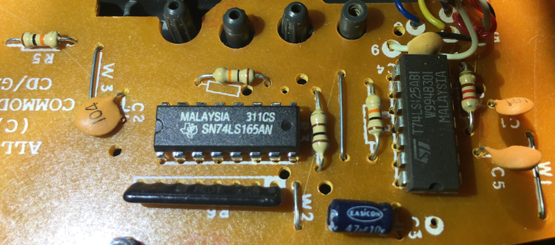
http://gerdkautzmann.de/cd32gamepad/a100schematic.png

At first I assumed the schematic had an error, because the physical hardware has
a 220R resistor (rightmost in the photo), rather than the 2K2 resistor at the bottom of the schematic.
The buffer around it are tri-state buffers, and the 2K2 ? resistor holds the outputs
normally low if the buffers are switched high impedance between their inputs & outputs.

Now it seems to me the 220R value is harsh for a pulldown resistor.
If the outputs became high, the 220R seems a bit close to short to be in the logic circuit.
Am I correct in my thinking, and it should be 2K2 ?


Offline tatus1969

  • Super Contributor
  • ***
  • Posts: 1273
  • Country: de
  • Resistance is futile - We Are The Watt.
    • keenlab
Re: Suspect resistor value
« Reply #1 on: August 01, 2016, 01:55:26 pm »
the 74LS125 has a max output high current of 2.6mA, which is by far exceeded by the 220R. You could measure the high-level voltage and check if it is above 2.0V.

2k2 seems by far more reasonable. Maybe they had timing problems, as they serially clock out data from the 74LS165. But I would rather solve that by software then...

Did you reverse-engineer the circuit? The schematic seems to be incorrect.
We Are The Watt - Resistance Is Futile!
 
The following users thanked this post: @rt

Offline @rtTopic starter

  • Super Contributor
  • ***
  • Posts: 1059
Re: Suspect resistor value
« Reply #2 on: August 01, 2016, 02:14:10 pm »

Hi :) It wasn’t me that drew the schematic, but I did a prototype from it, except I used a 220R resistor, and it does work.


the 74LS125 has a max output high current of 2.6mA, which is by far exceeded by the 220R. You could measure the high-level voltage and check if it is above 2.0V.

2k2 seems by far more reasonable. Maybe they had timing problems, as they serially clock out data from the 74LS165. But I would rather solve that by software then...

Did you reverse-engineer the circuit? The schematic seems to be incorrect.


Share me

Digg  Facebook  SlashDot  Delicious  Technorati  Twitter  Google  Yahoo
Smf