Post the schematic.
The LM324 seems to be a poor choice for a PWM circuit, because it's very slow.
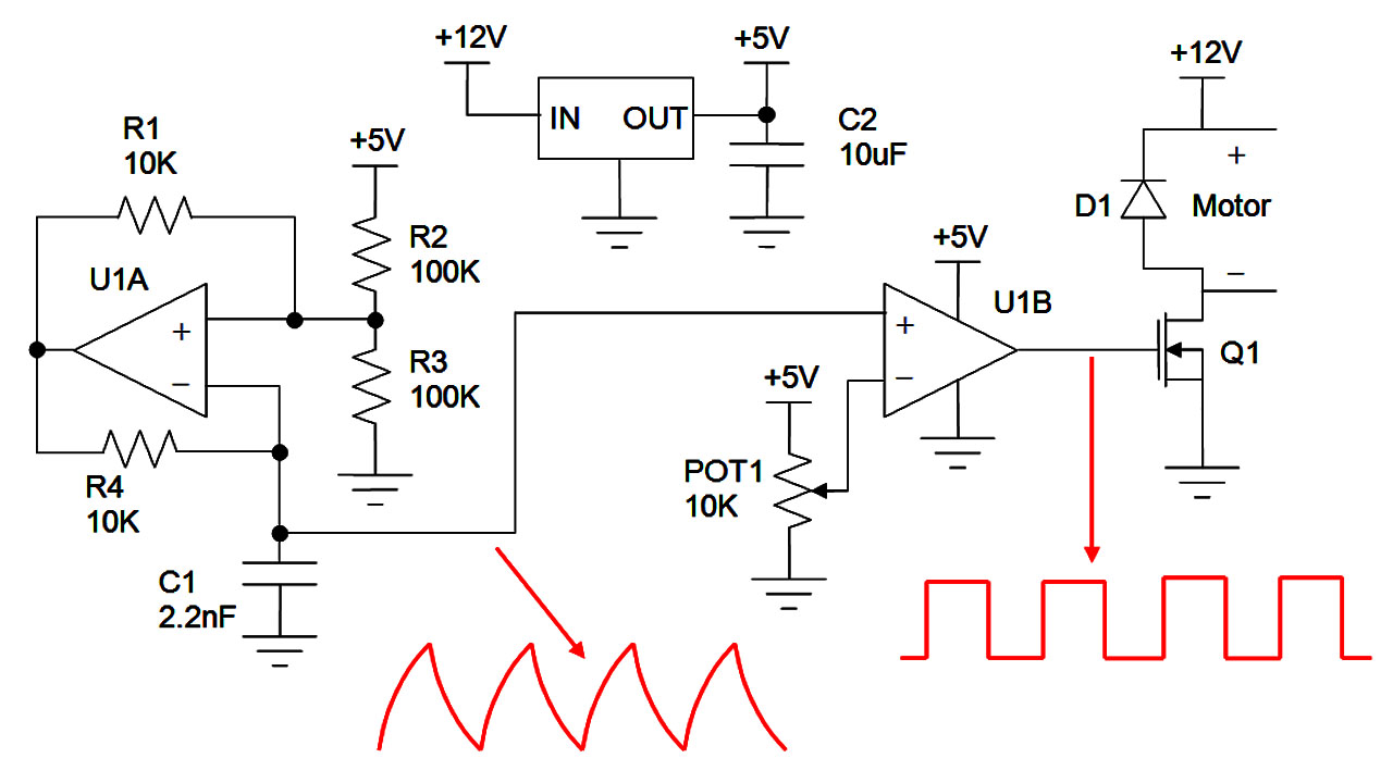
The LM324 is no good for that circuit. Use a comparator IC with a push-pull output, such as the LMC6762 or TLC3702. Alternatively, the LM393 or LM339 will work with 1k pull-up resistors to 5V.
You'll need to make sure the MOSFET can pass the required current, with a gate voltage of 5V. Consider powering the PWM circuit off 9V, directly from 12V or using a MOSFET driver IC.
What's the maximum expected supply voltage? Will this be run off a car's electrical system? It may be necessary to add some overvoltage protection circuitry


