Author Topic: Vacuum fluorescent display to clock display  (Read 50620 times)

0 Members and 2 Guests are viewing this topic.

Offline neoTopic starter

  • Super Contributor
  • ***
  • Posts: 1694
  • Country: us
  • The specialist.
Re: Vacuum fluorescent display to clock display
« Reply #75 on: September 29, 2016, 12:09:49 am »
ok i know im changing the rules but im going to use MM58342 (http://www.ti.com/lit/ds/symlink/mm58342.pdf) due to it being dip and also due to how many segments it can display

grid control

int IO1 = 6;
int IO2 = 7;
int IO3 = 8;
int IO4 = 9;
int IO5 = 10;
int IO6 = 11;
int IO7 = 12;
int IO8 = 13;


void setup() {
  pinMode (IO1, OUTPUT);
  pinMode (IO2, OUTPUT);
  pinMode (IO3, OUTPUT);
  pinMode (IO4, OUTPUT);
  pinMode (IO5, OUTPUT);
  pinMode (IO6, OUTPUT);
  pinMode (IO7, OUTPUT);
  pinMode (IO8, OUTPUT);
}

void loop()
 {
 digitalWrite (IO1, LOW);
 digitalWrite (IO2, LOW);
 digitalWrite (IO3, LOW);
 digitalWrite (IO4, LOW);
 digitalWrite (IO5, LOW);
 digitalWrite (IO6, LOW);
 digitalWrite (IO7, LOW);
 digitalWrite (IO8, LOW);
 delay (1);
 digitalWrite (IO1,HIGH);
 delay (1);
 digitalWrite (IO1,LOW);
 delay (.25);
 digitalWrite (IO2,HIGH);
 delay (1);
 digitalWrite (IO2,LOW);
 delay (.25);
 digitalWrite (IO3,HIGH);
 delay (1);
 digitalWrite (IO3,LOW);
 delay (.25);
 digitalWrite (IO4,HIGH);
 delay (1);
 digitalWrite (IO4,LOW);
 delay (.25);
 digitalWrite (IO5,HIGH);
 delay (1);
 digitalWrite (IO5,LOW);
 delay (.25);
 digitalWrite (IO6,HIGH);
 delay (1);
 digitalWrite (IO6,LOW);
 delay (.25);
 digitalWrite (IO7,HIGH);
 delay (1);
 digitalWrite (IO7,LOW);
 delay (.25);
 digitalWrite (IO8,HIGH);
 delay (.25);
}

and schematic below (simplified one pin only)

so i have the grid part done but i still dont understand the rest of it, also below is my attempt at making the font array const
A hopeless addict (and slave) to TEA and a firm believer that high frequency is little more than modern hoodoo.
 

Offline Ian.M

  • Super Contributor
  • ***
  • Posts: 12860
Re: Vacuum fluorescent display to clock display
« Reply #76 on: September 29, 2016, 12:54:51 am »
No problem changing chips.  All the SPI HV drivers that don't have a configuration register are very similar, and I, in common with a lot of other engineers try to avoid Maxim!  It probably wont affect the code you'd be writing significantly except for the need to send more bytes to change all its outputs.

The correct definition for the array would be:
Code: [Select]
const unsigned int font[]={unless you arre using the C99 fixed width  types from stdint.h, in which case you'd use:
Code: [Select]
const uint16_t font[]={
That's a horrible thing to do to the grid pins and wont work as the MOSFET body diode will conduct all the time. Its also totally unnecessary.  Normally you drive them just like an anode pin, (maybe with an extra current limiting resistor in series), directly from the same type of driver as the anodes.   If you want to drive the grids direct from the arduno, use the discrete transistor circuit I posted earlier, but its much simpler just to hook them to the SPI VFD driver, adding another daisychained chip if you have to.  To get the negative grid bias required for good cut-off and minimal ghosting, you bias the cathode (filament) positive via the center tap of the filament supply. A simple Zener to ground from there sets the cathode voltage and thus the grid cut-off bias.

If you intend to drive the grids via discrete drivers controlled directly by the Arduino pins, you'd want them all on the same AVR port for efficiency in shifting a single '0' in a byte of seven '1's across them to pulse one high at a time to multiplex them. Port D is the best bet.  Arrange the grids in port D bit order.   Alternatively get a 74HC138  decoder, and drive the grids with its 8 outputs, with three address lines from the Arduino to select one of them and  save 5 Arduino pins.  See https://www.arduino.cc/en/Hacking/PinMapping168 

You need to reserve the SPI pins for the SPI VFD driver. See https://www.arduino.cc/en/Reference/SPI for how to do SPI on an Arduino.

In other news, I've patched in Starburst16 support in my font editor, and am now slowly working on cleaning up and commenting the VBA code.  It uses Excel 5 dialog sheets so running it on recent Excel versions may be problematic.  Excel 5 dialog event handling really sucks and I've got a lot of kludges working around that and some Excel bugs.  However its less of a PITA than drawing polygons on Excel forms.
« Last Edit: September 29, 2016, 01:19:46 am by Ian.M »
 

Offline neoTopic starter

  • Super Contributor
  • ***
  • Posts: 1694
  • Country: us
  • The specialist.
Re: Vacuum fluorescent display to clock display
« Reply #77 on: September 29, 2016, 02:51:11 am »
the only reason i was toying with the mosfet idea is to save chip pins, but if it wont work i guess i dont have much of a choice also i have no clue on the rest of the code
A hopeless addict (and slave) to TEA and a firm believer that high frequency is little more than modern hoodoo.
 

Offline neoTopic starter

  • Super Contributor
  • ***
  • Posts: 1694
  • Country: us
  • The specialist.
Re: Vacuum fluorescent display to clock display
« Reply #78 on: September 29, 2016, 04:44:30 am »
i just realized something, won't the grid pins work at ground potential? that is to say when i tested it to map it out they were and it worked, if they can function as ground then it becomes much simpler AND saves io/driver chip pins
« Last Edit: September 29, 2016, 04:54:27 am by neo »
A hopeless addict (and slave) to TEA and a firm believer that high frequency is little more than modern hoodoo.
 

Offline technotronix

  • Regular Contributor
  • *
  • Posts: 210
  • Country: us
    • PCB Assembly
Re: Vacuum fluorescent display to clock display
« Reply #79 on: September 29, 2016, 07:08:35 am »
i should note at this point to trying to learn how to program and do microcontrollers but only if i can actually do it and not stare at a screen for 3 hours trying to tell my computer that there is an arduino attached and failing. so as more eloquently put im open to it so long as i can do it without hitting a brick wall just trying to set it up.

I am also at the same situation. I don't know much programming and facing some of the serious problems.
 

Offline Ian.M

  • Super Contributor
  • ***
  • Posts: 12860
Re: Vacuum fluorescent display to clock display
« Reply #80 on: September 29, 2016, 08:32:32 am »
i just realized something, won't the grid pins work at ground potential? that is to say when i tested it to map it out they were and it worked, if they can function as ground then it becomes much simpler AND saves io/driver chip pins
Depends what you mean by 'work'   Inactive grids or anodes at 0V = OFF.  The VFD tube acts as an AND gate - the specific segment only lights if both its grid and anode are positive. 

However you need to read the Futaba link I gave you again.  As far as the tube knows all voltages are measured relative to the center of its filament and the grid actually needs to be negative relative to that to totally cut off the active segments of the digit its trying to blank.    You could keep the filament at an average of 0V and shift all the anode and grid signals 25V negative and drive between there and your 5V rail, but the driver chips you've been looking at aren't designed for that so it would be a real PITA compared to using cathode bias.
 

Offline neoTopic starter

  • Super Contributor
  • ***
  • Posts: 1694
  • Country: us
  • The specialist.
Re: Vacuum fluorescent display to clock display
« Reply #81 on: September 29, 2016, 09:30:49 am »
One display and its led to 4 pages of theories, i have no clue how to code and apparently im a stumbling idiot everywhere else also. Every idea i come up with either leads to more than i can afford or nothing at all (or at least nothing i know how to do).
« Last Edit: September 29, 2016, 09:38:58 am by neo »
A hopeless addict (and slave) to TEA and a firm believer that high frequency is little more than modern hoodoo.
 

Offline Ian.M

  • Super Contributor
  • ***
  • Posts: 12860
Re: Vacuum fluorescent display to clock display
« Reply #82 on: September 29, 2016, 10:22:30 am »
That's why we'll help you bring it up in stages.  e.g
  • finalise hardware design
  • build and basic hardware testing
  • Develop software

Software
  • one static digit
  • multiplex whole display with static digits
  • display incrementing number
  • basic 12H or 24H clock, with switch to run at x60 speed for testing
  • fully functional clock

Digikey lists the  MM58342N as obsolete, zero stock, and other major distributors don't even have a listing for them any more. Don't design them in unless you have enough on hand + spares and have done enough testing to be certain they aren't fakes.

Design decision time:   Do you want to drive the grids separately or through the same type of SPI VFD driver you propose for the anodes?

IIRC you have 23 pins to drive on the tube so either you need enough SPI driver outputs to handle that or you need to split off the grids to a separate driver or you could parallel the center horizontal segments and ground the unused radials to turn it into a 7 segment display.

If you want to drive them separately from individual logic signals and you dont want a mess of discretes cluttering up your board, look at MIC2981  8 channels of logic level translation + high side drivers, good up to 50V in a PDIP-18 package.   You'd need pulldown resistors from each output to ground to guarantee complete turnoff.  100K should do it as anode or grid current is negligable when biased more negative than cutoff.   Input would be direct from your Arduino or via a 74HC238 3 to 8 line active high decoder.
« Last Edit: September 29, 2016, 10:27:03 am by Ian.M »
 

Offline Buriedcode

  • Super Contributor
  • ***
  • Posts: 1611
  • Country: gb
Re: Vacuum fluorescent display to clock display
« Reply #83 on: September 29, 2016, 10:28:10 am »
One display and its led to 4 pages of theories, i have no clue how to code and apparently im a stumbling idiot everywhere else also. Every idea i come up with either leads to more than i can afford or nothing at all (or at least nothing i know how to do).

Then take a step back and be guided by the restrictions you have.   For example, a VFD driver chip you want is very expensive and takes 6 weeks shipping?  Use something else.  You need to learn programming to use a different chip?  Well, that doesn't cost anything except time - and it's a great excuse to learn!   Doing everything discretely, as you've probably seen from the replies, a bit of an arse, but certainly doable if not a hell of a lot of effort.

If I were you, I would make a list of all the VFD driver chips mentioned - most require SPI so you'll be using your Arduino no matter what - and make notes of cost and availability, and 'ease of use' - for prototyping  the SMD parts will need adapters, so that adds to cost.  I couldn't really find the MM58342 here in the UK, but prices seems to hover around $20.  Which is steep.

Ideally, you could find a VFD driver chip and copy the 'example schematic' from its datasheet, hook up your VFD and Arduino to it, and provide the appropriate power supply, then it should just be a case of programming.
 

Offline neoTopic starter

  • Super Contributor
  • ***
  • Posts: 1694
  • Country: us
  • The specialist.
Re: Vacuum fluorescent display to clock display
« Reply #84 on: September 29, 2016, 10:29:27 am »
One display and its led to 4 pages of theories, i have no clue how to code and apparently im a stumbling idiot everywhere else also. Every idea i come up with either leads to more than i can afford or nothing at all (or at least nothing i know how to do).
I couldn't really find the MM58342 here in the UK, but prices seems to hover around $20.  Which is steep.

for me i can get 5 for that price, my trouble is i have no clue how to code and no one seems to be able to give me an example of what to do rather than telling me what needs done, i do appreciate the help it just does me little good when i don't know enough to go off and do it. I have read easily a hundred google found articles and they are not helping. And while a pain in the arse that they are discreet solutions i actually can somewhat understand, for example a high side mosfet switch (if done right not like the shortcut i previously suggested) would enable me to drive the display off of logic level signals
« Last Edit: September 29, 2016, 10:57:02 am by neo »
A hopeless addict (and slave) to TEA and a firm believer that high frequency is little more than modern hoodoo.
 

Offline neoTopic starter

  • Super Contributor
  • ***
  • Posts: 1694
  • Country: us
  • The specialist.
Re: Vacuum fluorescent display to clock display
« Reply #85 on: September 29, 2016, 10:45:01 am »
as for the design decision , separate if output pins from vfd driver are limited
A hopeless addict (and slave) to TEA and a firm believer that high frequency is little more than modern hoodoo.
 

Offline neoTopic starter

  • Super Contributor
  • ***
  • Posts: 1694
  • Country: us
  • The specialist.
Re: Vacuum fluorescent display to clock display
« Reply #86 on: September 29, 2016, 10:56:40 am »
ok heres something digikey has (read as not china) that would work perfectly from my perspective,
http://www.digikey.com/product-detail/en/microchip-technology/HV5812P-G/HV5812P-G-ND/4902558

i would need two but at that price its more than reasonable
A hopeless addict (and slave) to TEA and a firm believer that high frequency is little more than modern hoodoo.
 

Offline Ian.M

  • Super Contributor
  • ***
  • Posts: 12860
Re: Vacuum fluorescent display to clock display
« Reply #87 on: September 29, 2016, 10:59:28 am »
Roadmap for development without waiting for expensive/rare parts.
  • Get a string of two 74HC595 SIPO shift registers directly driving common anode seven segment LEDs working - that will teach you all you need to know about using the Arduino SPI libraries.
  • Then add 5V high side PNPs or MOSFETs for each digit controlled by '595 outputs and 6 more LED digits, connecting all cathodes for the same segment position in parallel to the same '595 pin.  That will teach you multiplexing over SPI
  • You can also experiment here with direct driving the high side transistors or using a 74HC138 deMUX.
  • Either switch to a chain of dedicated SPI VFD drivers or add MIC2981 high side drivers to the '595 (or other multiplexing logic) outputs.  Add an adjustable supply that can go up to 30V. If you wire your VFD for 7 segments, it will work with your LED code with minimal changes
  • If you are using them, add extra '595 and MIC2981, rewire your display so all anode wires have their own driver pin, and swap in my font table to see your display in its full 14 segment glory
  • To get it off breadboard now its working, design your own PCB with an ATmega328P so you can ditch the separate Arduino, and get it manufactured.  For chips/parts under $2.50 buy a separate set rather than stripping them off your breadboard so you can keep the breadboard version working in case you run into any problems.

Its time to 'get off the can', start building hardware and tinkering with code to drive it. . . .

The Microchip (ex Supertex) HV5812 display drivers are nice parts for this.  Definitely get two.  You should be able to drive common anode 7 segment LEDs + 6K8 series segment resistors from them (rather inefficiently) at their minimum  Vpp supply voltage of 20V.  This will help with software testing before you've got your VFD filament supply circuit built and debugged.
« Last Edit: September 29, 2016, 11:11:14 am by Ian.M »
 

Offline neoTopic starter

  • Super Contributor
  • ***
  • Posts: 1694
  • Country: us
  • The specialist.
Re: Vacuum fluorescent display to clock display
« Reply #88 on: September 29, 2016, 11:03:57 am »
the only problem with me getting off my can is i can't just order and have it i either wait a month on china, pay a premium for us ebay or wait until my next digikey order in a month, good news is i have 7 segment common anode leds on hand.
If i got the 74HC595 shift registers off of ebay in america, do you think it would take me a month or so to get to the point in need more of the end design hardware?
« Last Edit: September 29, 2016, 11:12:38 am by neo »
A hopeless addict (and slave) to TEA and a firm believer that high frequency is little more than modern hoodoo.
 

Offline Ian.M

  • Super Contributor
  • ***
  • Posts: 12860
Re: Vacuum fluorescent display to clock display
« Reply #89 on: September 29, 2016, 11:19:06 am »
OK. Waiting for parts is a PITA.

Do you have any logic chips for 3 to 8 line decoders or serial in parallel out shift registers or even enough D type flipflops to build a chain of 8 of them on hand?   If so we can help you breadboard a multiplexed 7 segment LED display so you can start getting to grips with the software.  List what you've got on hand.

I cant say how long it will take you - the software side may just 'click' in a weekend for you, or it may take a month of wrestling with the code, with a forum thread helping you debug it.  Anyone of average or above intelligence and sufficient commitment can be taught to program adequately, but some have the mind-set that gives them a natural aptitude for coding in procedural sequential languages.

I suggest putting the HV5812 chips on your next Digikey order.  If you don't already have them I would also suggest adding 5x (depending on your spare cash)  of 74HC595 SIPO shift registers, MIC2981 high side drivers, ULN2803 low side drivers, and a couple of 74HC138 and 74HC238 chips.  That should cover you for most future output interfacing and display multiplexing experiments.  I've just checked and everything except the HV5812 chips can also be found on Amazon if you are in a hurry.

« Last Edit: September 29, 2016, 11:28:35 am by Ian.M »
 

Offline neoTopic starter

  • Super Contributor
  • ***
  • Posts: 1694
  • Country: us
  • The specialist.
Re: Vacuum fluorescent display to clock display
« Reply #90 on: September 29, 2016, 11:43:25 am »
 i have about a dozen MC14013b Dual D Flip-Flop with Set and Reset
one special flip flop i got is a SN74LS174N HEX D FLIP-FLOP made by amd
as for multiplexing chips
SN74LS155N DUAL 1-OF-4 DECODER/ DEMULTIPLEXER
DM74LS158N Quad 2-Line to 1-Line Data Selectors/Multiplexers
SN74LS157N QUADRUPLE 2-LINE TO 1-LINE DATA SELECTORS/MULTIPLEXERS
SN74LS151NS DATA SELECTORS/MULTIPLEXERS
74LS253M 3-STATE Data Selector/Multiplexer

74LS395N 4-Bit Shift Register with TRI-STATE Outputs   4 of them
SN74LS595BN 8-BIT SHIFT REGISTERS WITH OUTPUT LATCHES  1 of them
SN74LS164N 8-BIT PARALLEL-OUT SERIAL SHIFT REGISTERS   3 of them
N82775 DUAL 8-BIT SHIFT REGISTER   1 of them

for your convenience i included a copy of my board list but its incomplete so i dont recomend looking unless you know what for, i have alot of old circuit boards lying around on that list is but a mere 10% or so of the total
« Last Edit: September 29, 2016, 11:52:46 am by neo »
A hopeless addict (and slave) to TEA and a firm believer that high frequency is little more than modern hoodoo.
 

Offline Ian.M

  • Super Contributor
  • ***
  • Posts: 12860
Re: Vacuum fluorescent display to clock display
« Reply #91 on: September 29, 2016, 12:05:43 pm »
Lets start with the 74LS595 controlling one LED digit with no multiplexing, and get you happy with sending segment patterns to it with the Arduino SPI library then add the 74LS155 wired as a 3 to 8 line decoder driven by three Arduino pins and some PNP transistors to support up to 8 multiplexed digits.

Do you think you know how to hook up the '595 with only one digit, or do you need help?
« Last Edit: September 29, 2016, 12:08:09 pm by Ian.M »
 

Offline neoTopic starter

  • Super Contributor
  • ***
  • Posts: 1694
  • Country: us
  • The specialist.
Re: Vacuum fluorescent display to clock display
« Reply #92 on: September 29, 2016, 12:09:52 pm »
i can probably connect it but the only pnps i have are from the 80s and i wouldnt know how to code it, and the part that gets to multiplexing i wouldn't know how to wire
« Last Edit: September 29, 2016, 12:11:23 pm by neo »
A hopeless addict (and slave) to TEA and a firm believer that high frequency is little more than modern hoodoo.
 

Offline neoTopic starter

  • Super Contributor
  • ***
  • Posts: 1694
  • Country: us
  • The specialist.
Re: Vacuum fluorescent display to clock display
« Reply #93 on: September 29, 2016, 12:15:22 pm »
well i do have some newer pnps but id have to hunt them down out of tv circuitry
A hopeless addict (and slave) to TEA and a firm believer that high frequency is little more than modern hoodoo.
 

Offline neoTopic starter

  • Super Contributor
  • ***
  • Posts: 1694
  • Country: us
  • The specialist.
Re: Vacuum fluorescent display to clock display
« Reply #94 on: September 29, 2016, 12:44:29 pm »
for the code to do it i got this from sparkfun, will it work?
A hopeless addict (and slave) to TEA and a firm believer that high frequency is little more than modern hoodoo.
 

Offline Ian.M

  • Super Contributor
  • ***
  • Posts: 12860
Re: Vacuum fluorescent display to clock display
« Reply #95 on: September 29, 2016, 01:47:20 pm »
No worries about the PNPs being 1980's.  A lot of my 'random stuff' parts bins are metal can transistors from the '70s and they are still fine for breadboarding as long as you don't let the cans touch!  Give me part numbers and I'll tell you if they'll do.

Here's the hookup.  Start with one digit and the anode direct to +5, then add the '155, transistors and other digits when you have the first digit working.


CP is 595 shift clock. ST is its store clock. All logic chips to be hooked up to +5V and 0V with 0.1uF decoupling across their power/gnd pins.

Don't know about the sparkfun code.  Give the URL of their page with the project or module description and I'll take a look.  It will probably need quite a few changes if it isn't using similar chips (i.e any flavour of '595 and a 3 to 8 decoder).

« Last Edit: September 29, 2016, 01:52:00 pm by Ian.M »
 

Offline neoTopic starter

  • Super Contributor
  • ***
  • Posts: 1694
  • Country: us
  • The specialist.
Re: Vacuum fluorescent display to clock display
« Reply #96 on: September 29, 2016, 08:50:22 pm »
i only have the one SN74LS595BN
and transistor part numbers
 2,   2n3800
 1,   2n1039
 10, 2n2905
 15, 2n1132
 3,   2n4036
 1,   2n2907a
 1,   2n3639
 1,   2n1119
 1,   2n988

i certainly hope that the 2n1132 or 2n905 will work their my majority

sparkfun link https://learn.sparkfun.com/tutorials/shift-registers
« Last Edit: September 29, 2016, 09:05:00 pm by neo »
A hopeless addict (and slave) to TEA and a firm believer that high frequency is little more than modern hoodoo.
 

Offline Ian.M

  • Super Contributor
  • ***
  • Posts: 12860
Re: Vacuum fluorescent display to clock display
« Reply #97 on: September 29, 2016, 09:18:44 pm »
2N2905 is an entirely adequate PNP switching transistor.  Its HFE is a little shitty compared to modern devices (min. 75 @Ic=10mA) and of course its in a big clumsy TO-39 can, but I wouldn't say no to a bag of them myself!  Its even got a high enough voltage rating to be satisfactory if you need to use it on your HT rail for your VFD.  Remember: Emitter by tab

2N1132 is rather less satisfactory: HFE min. 25 @Ic=5mA, and I'd have to be truly desperate to use it.

I'll take a look at the Sparkfun link and get back to you.

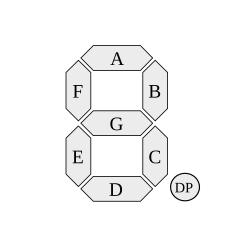
NOTE '595 to LED segment ordering.  D.P on the MSB then segments in alphabetical order with decreasing bit significance, because it makes the code slightly easier later, (specifically if you need to enter font tables in binary).


NOTE 2: Don't try to run more than 1 or 2 digits of the Arduino's onboard 5V regulator. It isn't man enough for the job.  Use a 1A max 5V supply (+/-5%) or a separate voltage regulator from the unreg supply to the Arduino.  Don't just stuff a 7805 in the breadboard - if its ground leg comes loose it will kill your logic chips and probably your Arduino.  Critical stuff like that is best soldered!

Caution: Also DON'T use a 5V high current supply (e.g. old PC PSU) unless you protect the feed to your breadboard with a 1A or less polyfuse.  (you can salvage them off really old 10base2 Ethernet cards - look for a yellowish disk that resembles a cap).  Using a supply without a low enough current limit frequently results in a melted breadboard and blown chips at the slightest wiring mistake.   Before using a USB charger or similar, check its output's a clean 5V (if you don't have a scope, stick a 1uF cap in series with your DMM to block the DC and put it on AC).  You are looking for less than 0.05V ripple (0.15V pk-pk on a scope), both unloaded and into a 100mA load, a DC voltage that is within 5% of nominal at no load and doesn't drop too much loaded, and a safe shutdown if you short the output.

If shorting it makes it go bang or it outputs more than 2A shorted, its best to find out before you use it for anything valuable.  Expect dirt cheap Chinese USB chargers to go bang!  Also their safety clearances are often totally inadequate and  you risk electrocuting yourself, your Arduino and your PC. . .  :-BROKE  :scared: :scared:

Get breadboarding!
« Last Edit: September 29, 2016, 10:01:01 pm by Ian.M »
 

Offline Ian.M

  • Super Contributor
  • ***
  • Posts: 12860
Re: Vacuum fluorescent display to clock display
« Reply #98 on: September 29, 2016, 09:47:25 pm »
OK quick followup.  The Sparkfun tutorial is for a PISO shift register to connect eight extra INPUTS.  That doesn't interest us for this project, so follow their link for output (SIPO) to bildr's 74HC595 Arduino tutorial.
 

Offline neoTopic starter

  • Super Contributor
  • ***
  • Posts: 1694
  • Country: us
  • The specialist.
Re: Vacuum fluorescent display to clock display
« Reply #99 on: September 29, 2016, 10:09:50 pm »
i must apologize, i cannot find the board SN74LS595BN is on
i have a bench top 5v supply that 1A and i also have a very nice wall wart that is 5v 850 ma
i have bought 10 x 74HC595 shift register they will be here on the 5th
« Last Edit: September 29, 2016, 10:15:52 pm by neo »
A hopeless addict (and slave) to TEA and a firm believer that high frequency is little more than modern hoodoo.


Share me

Digg  Facebook  SlashDot  Delicious  Technorati  Twitter  Google  Yahoo
Smf