Thanks everyone for all the input!
Would using a BJT instead of a MOSFET make things easier? Loosely speaking, BJTs don't really have a "base capacitance" with which to form a pole with the op-amp's output impedance?
I'm not sure your understanding of phase margin is correct. Phase margin is how far away your phase is from -180deg at the 0dB crossover frequency.
So your first circuit looks to have a phase margin of about 60deg, which is (arguably) quite optimal.
I'm prepared to agree that I don't know what phase margin is, but the first ("uncompensated") circuit I showed is definitely not optimal, as demonstrated by this transient response:
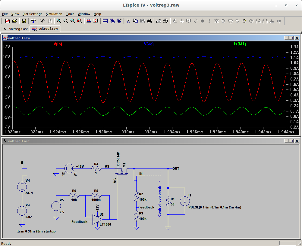
Maybe the confusion stems from the fact that I've cut the control loop and am looking at the response of the entire loop, inverting op-amp and all (instead of just the feedback network)? The Barkhausen stability criterion states that instability will occur if there exists a frequency such that phase shift
around the loop is a multiple of 360 and
loop gain is > 0dB. Nothing special about 180 degrees at all?? Maybe you're used to excluding the inverting opamp from your plots? Please correct me if I'm wrong!
When the gain is only a little above 1 the loop phase needs to be pretty close to -180 degrees to have a positive loop gain, and a risk of oscillation. If you are still well away from -180 degrees as the gain falls through unity you will always have negative feedback, and a stable loop. You seem to have confused the need to be positively away from -180 degrees with a need to have a positive phase.
As above, I'm sure you're right, but I don't understand where 180 degrees comes from. And, as shown above, it definitely isn't stable.
As tom66 said, the way you have added a capacitor forms a low pass filter, really slugging the loop's response. When you are well above the turnover frequency of this filter it gives you something very close to 90 degree of phase shift. In your loop its actually making the phase margin much worse.
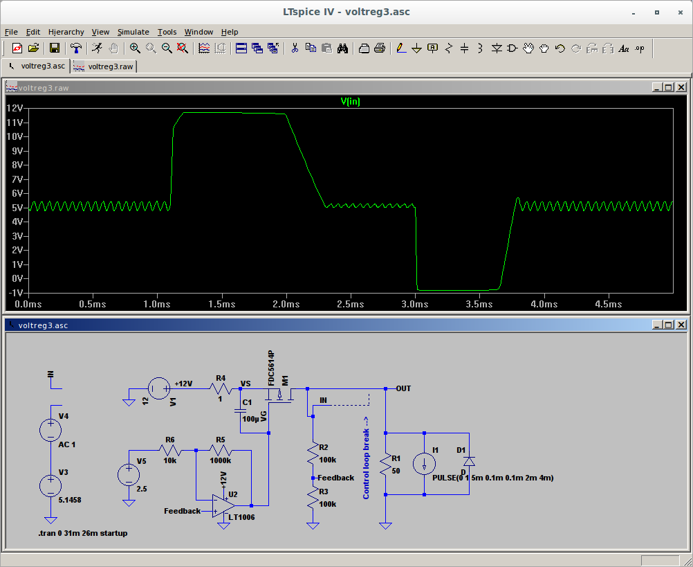
I'm glad to hear this because yes, that C obviously destroys the ability of the reg to deal with load steps. Again, I'm going to stop mentioning phase margin because I'm not sure I know what it means, but the addition of the C did make the loop
stable where it wasn't before? I assume this is what dominant pole compensation is; heavily attenuating the frequencies where the existing poles are so that they become irrelevant. I really wanted to find a better way though, of course.
In this circuit, one pole comes from the opamp (its internal pole, shifted up by the gain of R5/R6), and the second is the opamp's output with M1's gate capacitance. You've added a third pole, which only makes things more complicated. You could instead slow down the second pole by just adding more capacitance to M1's gate.
I added a capacitor across VGS -- I tried a bunch of values; and even if it's set to 100uF (which is clearly beyond absurd, I realise that), it still doesn't achieve stability. The reason I set it so large was to bring the poles apart so we can see each one, and it seems that the opamp output vs gate capacitance actually forms a
double pole/some sort of resonance (note the 180 degrees of phase change from 100 Hz to 1 kHz).
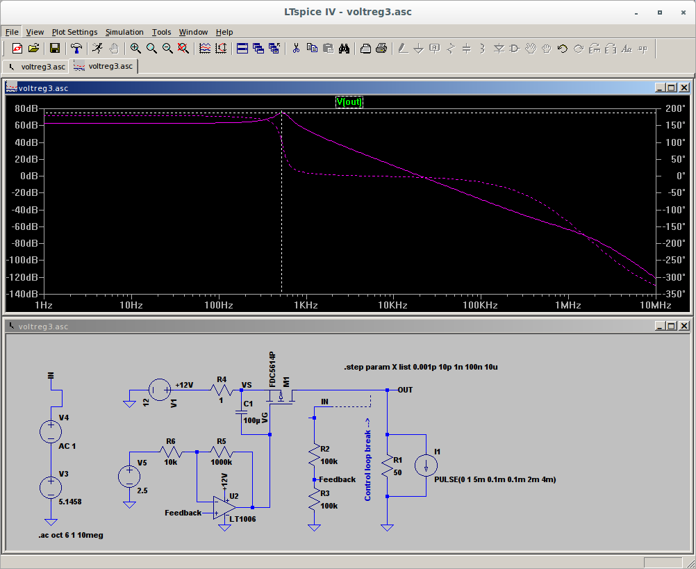
When phase reaches zero degrees, gain is still > 0dB, and the Barkhausen criteria correctly predicts instability:
If only I was moving a single pole, everything would be fine, right? Am I dealing with inductance in the op-amp output? Would using a BJT be better?
Why do you have R5/R6 there?
Not particularly good reasons:
-- To reduce the gain of the loop, which I thought was always a way to improve stability (correct me if I'm wrong)
-- In order to make biasing the loop when I cut it remotely possible (if I left the opamp
completely open loop, it would be nearly impossible to set V3 to keep the op-amp from saturating when finding the DC op point).
EDIT: Fixed broken image link.


