Recent Posts

Pages: Prev 1 2 3 4 5 6 [7] 8 9 10 Next
61
Test Equipment / Re: Choosing between entry-level 12-bit DSOs
« Last post by Mechatrommer on Today at 06:44:21 pm »
What is the length of your Lanczos filter?
well this is quite embarassing ;D iirc i set "wing" length as small as possible due to some complication i encountered earlier, extra ringing? iirc... length only like 2 or 3 :P i dont have indepth knowledge about it and its effect. thanks for your info, i'll looking into it deeper later...
62
These guys had reasonably priced printers when I was using them:
https://www.custom.biz/en_GB/product/hardware/printers/kiosk-receipt-printers/kpm180h

Most of them use ESC/POS or some kind of "binary" comms protocols.
ESC/POS is supported on multiple platforms, would not be surprised if someone also did an Arduino library for it.
63
I'm happy to say I have been able to repair the fault! I removed the CD4013 (IC5) using the 'soldering iron & pry' technique, as I didn't want to have to unsolder the immediately adjacent on/off switch to allow the use of hot air. This was a mistake, as the chip was glued to the PCB :(. Still, it eventually came off OK. I replaced it with a new part, and replaced R4 with a series combination of 100Ω and a BZX84C3V3 zener, which I happened to have in stock. Gradually winding up the supply voltage showed the Vdd supply still reached 18V with only 218VAC at the input - clearly the zener was not dropping enough volts at the very low operating current.

There is an unpopulated 0603 footprint 'R69' across the Vdd rail smoothing capacitor, so I fitted 3k3 in this position. This should give somewhere around the 5mA zener current required for correct operation. Vdd now measured 16.5V at 240VAC input - outside recommended working range, but well within the absolute maximum. Dissipation in R69 is comfortably less than its 0.1W rating. The set now draws approximately 1.0W from the mains supply in 'off' mode.

Unfortunately, it also draws about 1.7mA continuously from the batteries, when the mains lead is disconnected. Enough to completely drain them in about 12 months. As this is someone's 'kitchen radio', I doubt if it has ever had a set of batteries installed, but I will provide a warning anyway.
64
they make interesting components but can spoil all fun with just one thing

tin plated = silver plated

something strange with China. everything must be unbelievably cheap and unbelievable low quality and must look like 1milion  |O
65
Get out your red-blue anaglyphs, and see the football :)
It worked! 👍 :D
66
Projects, Designs, and Technical Stuff / Re: PC74hct4046ap Replacement
« Last post by Benta on Today at 06:31:33 pm »
instead of playing with the IC, try playing with R303, R304, R334 and C302.
Also adjust R302.
[/quote]

I agree. Optimizing the loop filter, aka loop controller will bring much more bang for your bucks.
Ultimately, using an active loop controller will probably result in best performance. But this is not an easy exercise.
67
Beginners / Re: Checking for noise in resistors
« Last post by TimFox on Today at 06:29:02 pm »
But what do you want to find? As I understand, the noisier the tube amp is - the better. Or not? If you don't want noise at all - use metalfilm resistors.

Who said that noise is a good thing in tube amps?
You are probably confused by advocates of single-ended amplifiers who like the even-order distortion from the circuit.
Metal film resistors work well with tubes, but sometimes the high resistance required may need metal oxide for practical applications.
68
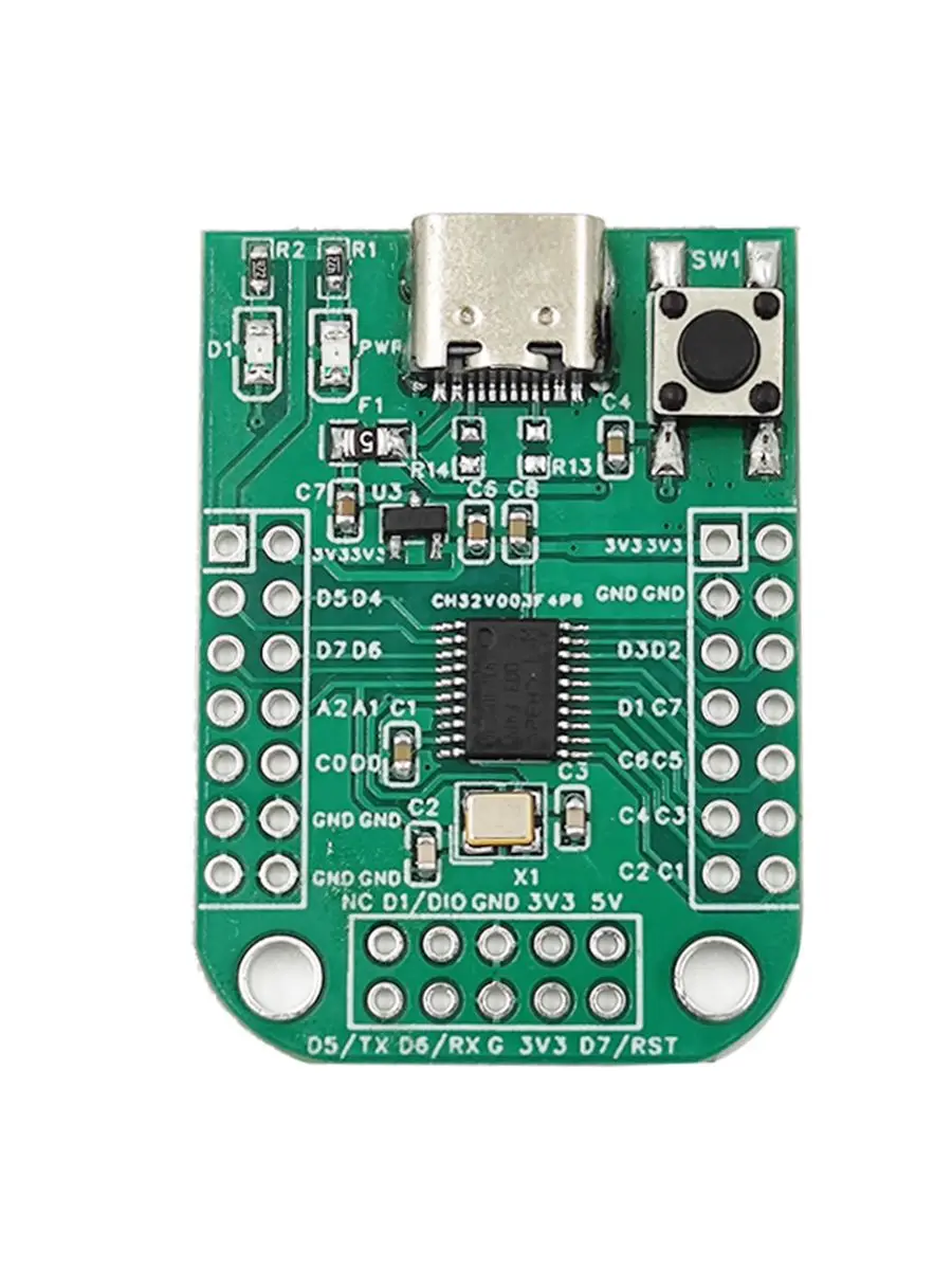
Microcontrollers / Re: CH32V003 using I2C mpu6050
« Last post by jlsilicon on Today at 06:27:20 pm »
I added an I2C Bus Scanner.

But it does not see the Mpu6060.
- Is the prolem that :
-- the I2C Bus Scanner code ,
-- or the mpu6050 wiring to Ch32v003f4p6 board ,
--  or does the Board Not support I2C - C1=SDA , C2=SCL ?

This is the Board :
-- Reset -> Reset PD7 pin
-- LED <- PD4


This is the schematic (except mine has a 10pin DIO Header) :
https://taunoerik.art/wp-content/uploads/2023/10/screenshot-from-2023-10-22-08-52-05.png

Code :

Code: [Select]

/*

 */

/*
 *@Note
 *Multiprocessor communication mode routine:
 *Master:USART1_Tx(PD5)\USART1_Rx(PD6).
 *This routine demonstrates that USART1 receives the data sent by CH341 and inverts
 *it and sends it (baud rate 115200).
 *
 *Hardware connection:PD5 -- Rx
 *                     PD6 -- Tx
 *
 */

#include "debug.h"

#include <ch32v00x_i2c.h>
#include <ch32v00x_rcc.h>


/* Global define */


/* Global Variable */
vu8 val;

/*********************************************************************
 * @fn      USARTx_CFG
 *
 * @brief   Initializes the USART2 & USART3 peripheral.
 *
 * @return  none
 */
void USARTx_CFG(void)
{
    GPIO_InitTypeDef  GPIO_InitStructure = {0};
    USART_InitTypeDef USART_InitStructure = {0};

    RCC_APB2PeriphClockCmd(RCC_APB2Periph_GPIOD | RCC_APB2Periph_USART1, ENABLE);

    /* USART1 TX-->D.5   RX-->D.6 */
    GPIO_InitStructure.GPIO_Pin = GPIO_Pin_5;
    GPIO_InitStructure.GPIO_Speed = GPIO_Speed_50MHz;
    GPIO_InitStructure.GPIO_Mode = GPIO_Mode_AF_PP;
    GPIO_Init(GPIOD, &GPIO_InitStructure);
    GPIO_InitStructure.GPIO_Pin = GPIO_Pin_6;
    GPIO_InitStructure.GPIO_Mode = GPIO_Mode_IN_FLOATING;
    GPIO_Init(GPIOD, &GPIO_InitStructure);

    USART_InitStructure.USART_BaudRate = 115200;
    USART_InitStructure.USART_WordLength = USART_WordLength_8b;
    USART_InitStructure.USART_StopBits = USART_StopBits_1;
    USART_InitStructure.USART_Parity = USART_Parity_No;
    USART_InitStructure.USART_HardwareFlowControl = USART_HardwareFlowControl_None;
    USART_InitStructure.USART_Mode = USART_Mode_Tx | USART_Mode_Rx;

    USART_Init(USART1, &USART_InitStructure);
    USART_Cmd(USART1, ENABLE);
}

//

/*
 *@Note
 7-bit addressing mode, master/slave mode, transceiver routine:
 I2C1_SCL(PC2)\I2C1_SDA(PC1).
  This routine demonstrates that Master sends and Slave receives.
  Note: The two boards download the Master and Slave programs respectively,
   and power on at the same time.
      Hardware connection:
            PC2 -- PC2
            PC1 -- PC1

*/

#include "debug.h"

/* I2C Mode Definition */
#define HOST_MODE   0
#define SLAVE_MODE   1

/* I2C Communication Mode Selection */
#define I2C_MODE   HOST_MODE
//#define I2C_MODE   SLAVE_MODE

/* Global define */
#define Size   6
#define RXAdderss   0x02
#define TxAdderss   0x02

/* Global Variable */
u8 TxData[Size] = { 0x01, 0x02, 0x03, 0x04, 0x05, 0x06 };
u8 RxData[5][Size];


/*********************************************************************
 * @fn      IIC_Init
 * @brief   Initializes the IIC peripheral.
 * @return  none
 */
void IIC_Init(u32 bound, u16 address)
{
    GPIO_InitTypeDef GPIO_InitStructure = {0};
    I2C_InitTypeDef  I2C_InitTSturcture = {0};

    RCC_APB2PeriphClockCmd( RCC_APB2Periph_GPIOC | RCC_APB2Periph_AFIO, ENABLE );
    RCC_APB1PeriphClockCmd( RCC_APB1Periph_I2C1, ENABLE );

    /// SDA : ///
    GPIO_InitStructure.GPIO_Pin   = GPIO_Pin_2;
    GPIO_InitStructure.GPIO_Mode  = GPIO_Mode_AF_OD;
    GPIO_InitStructure.GPIO_Speed = GPIO_Speed_50MHz;
    GPIO_Init( GPIOC, &GPIO_InitStructure );

    /// SCL : ///
    GPIO_InitStructure.GPIO_Pin   = GPIO_Pin_1;
    GPIO_InitStructure.GPIO_Mode  = GPIO_Mode_AF_OD;
    GPIO_InitStructure.GPIO_Speed = GPIO_Speed_50MHz;
    GPIO_Init( GPIOC, &GPIO_InitStructure );

    I2C_InitTSturcture.I2C_Mode        = I2C_Mode_I2C;
    I2C_InitTSturcture.I2C_OwnAddress1 = address;
    I2C_InitTSturcture.I2C_ClockSpeed  = bound;
    I2C_InitTSturcture.I2C_DutyCycle   = I2C_DutyCycle_16_9;
    I2C_InitTSturcture.I2C_Ack         = I2C_Ack_Enable;
    I2C_InitTSturcture.I2C_AcknowledgedAddress = I2C_AcknowledgedAddress_7bit;
    I2C_Init( I2C1, &I2C_InitTSturcture );

    I2C_Cmd( I2C1, ENABLE );

// #if (I2C_MODE == HOST_MODE)
    I2C_AcknowledgeConfig( I2C1, ENABLE );

// #endif

}

//

/*********************************************************************
 * @fn      main
 * @brief   Main program.
 * @return  none
 */
int main(void)
{
    NVIC_PriorityGroupConfig(NVIC_PriorityGroup_2);
    SystemCoreClockUpdate();
    Delay_Init();

    USART_Printf_Init(115200);
     printf("\r\n\r\n: I2C_MPU6050_003_2 : \r\n");
     printf(" SystemClk:%d\r\n",SystemCoreClock);
     printf( "ChipID:%08x\r\n", DBGMCU_GetCHIPID() );

    USARTx_CFG();

    //

// u8  i = 0;
u8  j = 0;
// u8  p = 0;
u8  res ;

// __IO uint32_t  i2creg=0 ;
__IO uint32_t   i2cxbase=0 , i2cxbase1=0 , i2cxbase2=0 ;
  i2cxbase = (uint32_t)I2C1 ;  // = (uint32_t)I2Cx;
//  i2creg = I2C_FLAG >> 28;
//  I2C_FLAG &= FLAG_Mask;
//  if(i2creg != 0)
//  {
//    i2cxbase += 0x18;
    i2cxbase1 = i2cxbase + 0x14;
//  }
//  else
//  {
//    I2C_FLAG = (uint32_t)(I2C_FLAG >> 16);
//    i2cxbase += 0x18;
    i2cxbase2 = i2cxbase + 0x18;
//  }


printf("> main(): IIC mode\r\n");
    IIC_Init( 80000, TxAdderss);

  while( 1 )
  {

printf("= main(): for(0..5) \r\n");
    for( j=0x01; j <= 0x7F ; j++ )
    {
       while( I2C_GetFlagStatus( I2C1, I2C_FLAG_BUSY ) != RESET );

printf("= main(): ->I2C:Start() \r\n");
      I2C_GenerateSTART( I2C1, ENABLE );
       while( ! I2C_CheckEvent( I2C1, I2C_EVENT_MASTER_MODE_SELECT ) ) {}

printf("  = main(): ->I2C:SendAdrId() = x%02X \r\n" , j );
//      I2C_Send7bitAddress( I2C1, 0x02, I2C_Direction_Transmitter );
//      I2C_Send7bitAddress( I2C1, 0x68, I2C_Direction_Transmitter );
      I2C_Send7bitAddress( I2C1, j, I2C_Direction_Transmitter );
//        while( ! I2C_CheckEvent( I2C1, I2C_EVENT_MASTER_TRANSMITTER_MODE_SELECTED ) ) {}
      res = I2C_CheckEvent( I2C1, I2C_EVENT_MASTER_TRANSMITTER_MODE_SELECTED ) ;
printf("    => MTM=%d " , res );
      res = I2C_CheckEvent( I2C1, I2C_Direction_Transmitter ) ;
printf(", DirT=%d " , res );
        Delay_Ms(1);

      res = I2C_CheckEvent( I2C1, I2C_EVENT_MASTER_TRANSMITTER_MODE_SELECTED ) ;
printf(", MTM=%d " , res );
//      res = I2C_GetFlagStatus( I2C1, I2C_EVENT_MASTER_BYTE_TRANSMITTED ) ;
      res = (*(__IO uint32_t *) i2cxbase1);
printf(", St=%d " , res );
      res = (*(__IO uint32_t *) i2cxbase2);
printf("%d " , res );

/*
        while( I2C_GetFlagStatus( I2C1, I2C_FLAG_TXE ) ==  RESET ) {}
            I2C_SendData( I2C1, TxData[i] );
       while( ! I2C_CheckEvent( I2C1, I2C_EVENT_MASTER_BYTE_TRANSMITTED ) )  {}
*/

printf("\r\n= main(): ->I2C:Stop() \r\n");
      I2C_GenerateSTOP( I2C1, ENABLE );
//      res = I2C_GetFlagStatus( I2C1, I2C_EVENT_MASTER_TRANSMITTER_MODE_SELECTED ) ;
      res = (*(__IO uint32_t *) i2cxbase1);
printf("      , St=%d " , res );
      res = (*(__IO uint32_t *) i2cxbase2);
printf("%d \r\n" , res );

       Delay_Ms(100);
    }

printf("\r\n---\r\n\r\n");
    Delay_Ms(1000);
  }  // - while(1) .

    //

    while( 1 )
    {
        ;
    }

    //

}

///

Also added to my github :
https://github.com/jlsilicon/Ch32v003/blob/main/Ch32v003/I2C_Bus_Scanner/User/main.c
69
Buy/Sell/Wanted / Re: FS: Motorola MVME 202, 310, 211
« Last post by LittleFrog on Today at 06:26:46 pm »
Hi,
I realise this thread is old, but please could I ask if you sold these boards?
Thanks, Dave
70
Test Equipment / Re: Choosing between entry-level 12-bit DSOs
« Last post by gf on Today at 06:25:14 pm »
All 4 channels on.
this is what i meant... perfect sine reconstruction.. i tuned my sim files to this setup, 220MHz sampled at 500MSps (f = Sr / 2.27), here is what i come up with. so it seems Rigol and VisaDSO got broken implementation.

What is the length of your Lanczos filter?
For example, lanczos3 has a reconstructability imit of sample_rate / 3.57, and for lanczos5 it is sample_rate / 2.72.
In order to achieve 2.27, you rather need lanczos10 or lanczos11.

EDIT: Added frequency response plots.

Pages: Prev 1 2 3 4 5 6 [7] 8 9 10 Next