Author Topic: Busted my Benchtop PSU  (Read 5319 times)

0 Members and 1 Guest are viewing this topic.

Offline TMFKSOFTTopic starter

  • Contributor
  • Posts: 11
  • Country: gb
  • Avid PHP Programmer and Electronics fanatic!
Busted my Benchtop PSU
« on: March 12, 2018, 02:08:18 am »
I'll preface this post with a disclaimer:
I'm an idiot that broke his craptastic benchtop PSU by being an idiot with it and has no clue how to fix it!

I recently bought a Benchtop Power supply from a local hobby shop and managed to murderise it by turning it up to 12v or and repeatedly toggling power on and off with something.
I don't remember what, this was a couple of weeks ago. Pretty much shorting the leads together repeatedly. Now it's stuck at spitting out 21v out the front, the dial on the front does absolutely nothing to affect it other than flicking the power button to completely stop current.

The Victim?
A Mercury RPS-V40, it's quite nice but only cost me £50


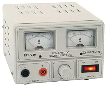
Rather than having it replaced, I'd like to have a look into it. By now it's out of the return period and it'd be rather shitty for me to try and claim it died at random.

I've got basic electronics knowledge but I'm trying to learn more as I go, however I don't fancy my odds playing with 230v while probing around inside.
While it's been turned on and sat at 21v with 0 amps it's BBQ'd a resistor on the main board inside. Pictures below:


I've not been able to work out what resistor should be in it's place. However I can confirm a good 23v is being thrown across it, way more than I assume it should normally.
After removing the resistor from the board the power supply now puts out a happy 5v that I can control with the front dial, though thats as high as it will go now.

It's range is 0-20v with a transformer inside that has 3 tapped voltages: 12v, 10v & 17v (In that order, see picture below).


I'm not familiar enough with the transformer to start probing it and know what the voltages mean. There's 5 wires coming off the secondary coil.
Though I don't know the function of all 5. I presume 3 of them are the taps at the aforementioned voltages, could the transformer be shorted?

What should I do next.
Any suggestions would be really appreciated, keep in mind I'm a beginner that's only ever really messed with basic circuits at ~5v so bigger voltage stuff is not in my area of knowledge.

For anyone daring enough to try and built a schematic of it to help track down the fault there's a transistor on the back too:
I found a PDF Spec sheet for it: http://www.onsemi.com/PowerSolutions/document/2N3055-D.PDF
Note: The transistor is labelled as a MJ2955.

Many thanks,
Thomas
« Last Edit: March 13, 2018, 12:52:40 am by TMFKSOFT »
 

Offline coromonadalix

  • Super Contributor
  • ***
  • Posts: 5906
  • Country: ca
Re: Busted my Benchtop PSU
« Reply #1 on: March 12, 2018, 02:28:56 am »
It is an lm723 based power supply,  maybe finding some schematics on google may help you

something like :

http://chemelec.com/Projects/LM723-PS/LM723-0.png
http://www.electroniq.net/power-supply/lm723-variable-power-supply.html

some basic implementation

http://www.rason.org/Projects/powsupply/powsupply.htm
« Last Edit: March 12, 2018, 02:33:47 am by coromonadalix »
 

Offline Rog520

  • Regular Contributor
  • *
  • Posts: 89
  • Country: us
Re: Busted my Benchtop PSU
« Reply #2 on: March 12, 2018, 04:10:36 am »
Looks like that burned resistor services the Vcc pin on the 723, as well as something off-board (there appears to be a blue wire connected at the opposite edge of the board via a PCB trace from this resistor). My guess is that it's a low-value resistor. Unless you can make out its value (or have a schematic available) I would be tempted to replace it with something like 10 ohms, and also replace the 723. Then check the 2N3055 for damage and replace it if necessary. Also trace that blue wire and see where it goes. After repair, power up slowly with a variac or something similar if you have one and check to see if the 723 or the resistor (or anything else for that matter!) is getting hot. It's worth a shot and probably won't make you any worse off that you already are!
 

Online Ian.M

  • Super Contributor
  • ***
  • Posts: 12860
Re: Busted my Benchtop PSU
« Reply #3 on: March 12, 2018, 05:25:23 am »
The fact the output voltage dropped from 21V to 5V when you removed the burnt resistor means it cannot have gone open-circuit.  There's a fair chance its somewhere near its original value.  Its resistance may have gone up a bit but measuring it may give you some idea of a possible replacement.

I strongly suspect that the 2N3055 pass transistor has failed.  While its supposedly good for about 5A with 23V across it, and I *ASS*U*ME* the PSU has some sort of fixed current limiting that kicks in at around 2A, that 5A rating form the S.O.A. graph in the datasheet is only applicable with the heatsink at 25 deg C.   Put a sustained short on the output and the transistor heats up the heatsink till it can no longer take the surge when you short it.

It would also be worth checking that relay - I *think* its a tap changer to select a lower input voltage to the bridge rectifier at low output voltages, and if its contacts have welded in the higher voltage position, that would result in pass transistor failure.

If you need to reverse-engineer it to get a schematic to help us work out a likely value for that resistor, you'll need to take well lit, in-focus photos of both sides of the board, square on, not skewed, and preferably against a white background, so we can help you overlay them to see the components on top of the track layout.   You'll also need to identify what each off-board wire goes to, and make a note of all component part numbers and/or values that can't easily be seen from the photos

Reverse engineering is hard work so lets try the simple stuff first.
« Last Edit: March 12, 2018, 05:27:03 am by Ian.M »
 

Offline Rog520

  • Regular Contributor
  • *
  • Posts: 89
  • Country: us
Re: Busted my Benchtop PSU
« Reply #4 on: March 12, 2018, 06:03:16 am »
Looking at the underside of the board again: is it just me or is there a bad solder joint on that relay?
 

Offline TMFKSOFTTopic starter

  • Contributor
  • Posts: 11
  • Country: gb
  • Avid PHP Programmer and Electronics fanatic!
Re: Busted my Benchtop PSU
« Reply #5 on: March 12, 2018, 02:14:43 pm »
Thanks for everyones responses! I didn't expect much of a response lol.

It is an lm723 based power supply,  maybe finding some schematics on google may help you

something like :

http://chemelec.com/Projects/LM723-PS/LM723-0.png
http://www.electroniq.net/power-supply/lm723-variable-power-supply.html

some basic implementation

http://www.rason.org/Projects/powsupply/powsupply.htm

Thanks for the links you provided, hopefully they'll be of use on my quest to fix the issue.

Looks like that burned resistor services the Vcc pin on the 723, as well as something off-board (there appears to be a blue wire connected at the opposite edge of the board via a PCB trace from this resistor). My guess is that it's a low-value resistor. Unless you can make out its value (or have a schematic available) I would be tempted to replace it with something like 10 ohms, and also replace the 723. Then check the 2N3055 for damage and replace it if necessary. Also trace that blue wire and see where it goes. After repair, power up slowly with a variac or something similar if you have one and check to see if the 723 or the resistor (or anything else for that matter!) is getting hot. It's worth a shot and probably won't make you any worse off that you already are!

I'm afraid I don't have a variac to hand to test with. However, the 2N3055 looks to be physically in good shape as does the 723. When I get chance I'll try my best to test them with my multimeter. I tried a dead short across where the resistor was and the cap next to D6 vented out the side (like that was a good idea to do). Maybe that helps in figuring out the layout :P

The fact the output voltage dropped from 21V to 5V when you removed the burnt resistor means it cannot have gone open-circuit.  There's a fair chance its somewhere near its original value.  Its resistance may have gone up a bit but measuring it may give you some idea of a possible replacement.

I strongly suspect that the 2N3055 pass transistor has failed.  While its supposedly good for about 5A with 23V across it, and I *ASS*U*ME* the PSU has some sort of fixed current limiting that kicks in at around 2A, that 5A rating form the S.O.A. graph in the datasheet is only applicable with the heatsink at 25 deg C.   Put a sustained short on the output and the transistor heats up the heatsink till it can no longer take the surge when you short it.

It would also be worth checking that relay - I *think* its a tap changer to select a lower input voltage to the bridge rectifier at low output voltages, and if its contacts have welded in the higher voltage position, that would result in pass transistor failure.

If you need to reverse-engineer it to get a schematic to help us work out a likely value for that resistor, you'll need to take well lit, in-focus photos of both sides of the board, square on, not skewed, and preferably against a white background, so we can help you overlay them to see the components on top of the track layout.   You'll also need to identify what each off-board wire goes to, and make a note of all component part numbers and/or values that can't easily be seen from the photos

Reverse engineering is hard work so lets try the simple stuff first.
Maybe, I removed the resistor before it completely died, I'll see if I can get a reading off it that hopefully may give clues as to what its original value was, however my gut feeling says that it's just a result of a fault elsewhere.

Whats the best way to test the transistor? I can't seem to fully figure out what pin is which and what to expect on my craptastic multimeter. I've shorted across the output (its glarious 5v output currently) the voltage sits at 0v when shorted as does the amperage. The transistor seems to get a little warm after a couple of minutes but nothing considerable.

Though the relay doesn't click at all when raising/lowering the voltage it doesn't appear to be stuck inside. It's a 12V relay and doesn't appear to get any voltage across either of its 3 pins. So maybe that's why its not actuating?

I'll do my best to take some images of the board and post them, at least to get an idea of what's what.

Looking at the underside of the board again: is it just me or is there a bad solder joint on that relay?
I presume you're referring to the solder joint next to the screw on the right? If so, there's nothing connected there for whatever reason :P
 

Offline Nusa

  • Super Contributor
  • ***
  • Posts: 2416
  • Country: us
Re: Busted my Benchtop PSU
« Reply #6 on: March 12, 2018, 02:30:18 pm »
Is it my imagination, or is that screw on the left on the backside bridging two solder pads?
 

Offline Rog520

  • Regular Contributor
  • *
  • Posts: 89
  • Country: us
Re: Busted my Benchtop PSU
« Reply #7 on: March 12, 2018, 02:41:38 pm »

I presume you're referring to the solder joint next to the screw on the right? If so, there's nothing connected there for whatever reason :P

No, there's a pad to the right of the 723 and below the large pour of solder (as I look at the picture of the underside of the board), which appears to have one of the relay pins poking through without being properly soldered.


Offline Rog520

  • Regular Contributor
  • *
  • Posts: 89
  • Country: us
Re: Busted my Benchtop PSU
« Reply #8 on: March 12, 2018, 02:50:13 pm »
The 3055 can be tested for shorts with a basic multimeter set on the lowest resistance range. If you have a meter with the diode check function you can probe with positive lead to base...and with negative lead to collector or emitter you should get about 0.6v. Any reading in any other position would indicate leakage or a short. The 723 would be hard to properly test. Since they're cheap I would just replace it as a matter of course.

Nusa has a point here, though, about that screw....
 

Online Andy Watson

  • Super Contributor
  • ***
  • Posts: 2085
Re: Busted my Benchtop PSU
« Reply #9 on: March 12, 2018, 10:30:51 pm »
A.K.A. Skytronic 650-673, this unit appears to be an over spec'd clone of a Velleman PS1502.
Edit: A.K.A. Quasar 650.673, PSU673

As far as I can tell, it corresponds to the schematic given on the last page of the Velleman PS1502A user manual. There are a few minor component value differences around the voltage feedback/control - as you might expect when the output is specified to 20V. R13 appears to be extra and is in parallel with R8 (! uh).
https://www.velleman.eu/support/downloads/?code=PS1502A
« Last Edit: March 18, 2018, 01:13:10 pm by Andy Watson »
 
The following users thanked this post: Ian.M

Offline Rog520

  • Regular Contributor
  • *
  • Posts: 89
  • Country: us
Re: Busted my Benchtop PSU
« Reply #10 on: March 12, 2018, 11:10:08 pm »
A.K.A. Skytronic 650-673, this unit appears to be an over spec'd clone of a Velleman PS1502.

As far as I can tell, it corresponds to the schematic given on the last page of the Velleman PS1502A user manual. There are a few minor component value differences around the voltage feedback/control - as you might expect when the output is specified to 20V. R13 appears to be extra and is in parallel with R8 (! uh).
https://www.velleman.eu/support/downloads/?code=PS1502A

And the one you link to is using a PNP as the pass transistor, whereas the supply in question apparently uses a 2N3055...so there's going to be some differences in component arrangement and connection to the 723.
 

Online Ian.M

  • Super Contributor
  • ***
  • Posts: 12860
Re: Busted my Benchtop PSU
« Reply #11 on: March 12, 2018, 11:42:12 pm »
AARGH!!! Its a PNP* pass transistor design without effective current limiting - LM723 pins 2 and 3 aren't even hooked up, and there doesn't appear to be any other active current limiting circuit!   |O

* The datasheet the O.P. linked includes the PNP MJE2955 as well as the titular NPN 2N3055, and board layout doesn't match any conceivable NPN pass transistor LM723 variant unless its got a PNP driver transistor off-board soldered directly to the pass transistor pins as a Sziklai pair.
 

Offline TMFKSOFTTopic starter

  • Contributor
  • Posts: 11
  • Country: gb
  • Avid PHP Programmer and Electronics fanatic!
Re: Busted my Benchtop PSU
« Reply #12 on: March 13, 2018, 12:36:12 am »
Thanks for the responses,

Is it my imagination, or is that screw on the left on the backside bridging two solder pads?
Good thinking, its not shorting across the two pads but it's all a hairs distance between them. I'll see if I can find a small plastic washer to try and avoid it ever doing that.

The 3055 can be tested for shorts with a basic multimeter set on the lowest resistance range. If you have a meter with the diode check function you can probe with positive lead to base...and with negative lead to collector or emitter you should get about 0.6v. Any reading in any other position would indicate leakage or a short. The 723 would be hard to properly test. Since they're cheap I would just replace it as a matter of course.

Nusa has a point here, though, about that screw....
Ah, thanks. I'll take a look. My multi-meters dirt cheap so hopefully It'll be able to give a decent idea. Without trying to sound stupid, would I be expecting 0.6v without power..?

As for the 723, I'll get one on order. Maybe a few. I should have a shot at making my own simple power supply circuit based off the posted schematics above :P

No idea what the correct terms would be to find a transformer with the different voltage taps.

A.K.A. Skytronic 650-673, this unit appears to be an over spec'd clone of a Velleman PS1502.

As far as I can tell, it corresponds to the schematic given on the last page of the Velleman PS1502A user manual. There are a few minor component value differences around the voltage feedback/control - as you might expect when the output is specified to 20V. R13 appears to be extra and is in parallel with R8 (! uh).
https://www.velleman.eu/support/downloads/?code=PS1502A
Most likely, there's very little documentation with the supply other than safety warnings and troubleshooting. There's no schematics in the manual other than telling me not to open it. but who needs warranty, right?

AARGH!!! Its a PNP* pass transistor design without effective current limiting - LM723 pins 2 and 3 aren't even hooked up, and there doesn't appear to be any other active current limiting circuit!   |O

* The datasheet the O.P. linked includes the PNP MJE2955 as well as the titular NPN 2N3055, and board layout doesn't match any conceivable NPN pass transistor LM723 variant unless its got a PNP driver transistor off-board soldered directly to the pass transistor pins as a Sziklai pair.

Yeah, this thing doesn't seem to have much protection. Truth be told this is the 2nd one I've killed. The first one I killed by having it sit at 12V for an extended amount of time at high current while messing with a peltier module. They replaced it for me with the one I've killed again! I'd hope there'd have been some protection against silly mistakes like this. The first one managed to murderise the transformer and it went open circuit.

To be honest I'm almost at the point of forcing myself to learn PCB Software (I generally want to) and design myself a PCB from the schematics above and build myself a new board and have it made. Would be an interesting project. Ideally after I've fixed this one :P
 

Offline TMFKSOFTTopic starter

  • Contributor
  • Posts: 11
  • Country: gb
  • Avid PHP Programmer and Electronics fanatic!
Re: Busted my Benchtop PSU
« Reply #13 on: March 13, 2018, 12:51:03 am »
Whoops, I may have ballsed up my original post a little.
The transistor is actually a MJ2955, Same sheet as linked in the OP.

Find attached some hopefully useful images of the board (top & bottom) as well as the transistor on the back.


I've tried my best to light the images.

Excuse my bad soldering job where I've touched up the aforementioned solder joint that Rog520 pointed out as well as another dirty looking solder joint that I made look worse :P
 

Online Ian.M

  • Super Contributor
  • ***
  • Posts: 12860
Re: Busted my Benchtop PSU
« Reply #14 on: March 13, 2018, 01:46:58 am »
I'm not surprised the previous one cooked its transformer.

*DONT* start from the schematics above - its about as brain-dead a LM723 PSU design as its possible to create.   

Implementing an effective 2A current limit would only have needed a 0.33R 2W resistor to be added - in the right place to trigger the LM723 internal current limiting circuit to pull down the output on over-current.

There's very little except the relay's natural difference between its pull-in and holding currents to stop it chattering - set the output voltage just so, with a bit of a load on it and you can probably get that relay to buzz till it dies.

Shrouded 4mm sockets make no sense whatsoever for a low voltage PSU.  There are no unsafe voltages so shrouding them is unnecessary, and the absence of binding posts just makes it harder to hook up to your load.

If you just want to hack the existing board to add a fixed current limit and maybe improve the relay tap changer we can probably help you mod it, but otherwise you'd be better off starting from the Philips schematics Oldway posted links to (and I posted a LTspice simulation of) in https://www.eevblog.com/forum/projects/how-do-make-a-current-limiting-knob-using-lm723-for-linear-reg-power-supplies/  If you can find panel space for its knob, it would be easy enough to add a variable current limit, and make the design close to bomb-proof.

Incidentally, LM723 was a stocked part at most Maplin stores, so if you've got one closing down near you it would be worth popping in and buying a couple - code # QL21X reduced to £0.35.   They are very unlikely to have more than 2 in stock so unless its a superstore, grab what they've got. 


IF tou are short of pass transistors, Maplin don't have MJE2955, but do have the TIP2955  TO-247 plastic package equivalent (# QH55K @ £0.50) You can bodge a TO-247 onto a TO-3 heatsink footprint.   However it may be better to use a 2N3055 (# BL45Y @£0.74) + a medium power PNP e.g BD442 (# N17AJ @£0.23) or BD912 (# N19AJ @£0.24) + a base-emitter resistor on the 2N3055 to surpress amplified leakage to make a PNP-equivalent Sziklai pair. The extra parts can probably be mounted directly to the 2N3055 TO-3 package pins and collector tag.

Otherwise if you aren't near a Maplin or its gone or been cleared out by the vultures, wait for consensus in this thread and order the right parts from a proper supplier with a UK distribution center.
 

Offline TMFKSOFTTopic starter

  • Contributor
  • Posts: 11
  • Country: gb
  • Avid PHP Programmer and Electronics fanatic!
Re: Busted my Benchtop PSU
« Reply #15 on: February 25, 2019, 02:17:54 am »
A year and a bump later..
Sorry mods please don't hurt me :(

This thing has sat on my shelf as I've had a busy year.
Last thing I did which I forgot to mention was I replaced the voltage switching chip the LM723.
I managed to pillage the last two from Maplins as they were closing. I even picked up a nice parts storage rack they kept the components in which has some goodies in such as an assortment of caps.
I managed to find a close matching cap to replace the one that had vented.

So here we are nearly a year later and I want to get this thing up and running. I've gotten myself a nice soldering iron too so I can work on this properly.
I digress..

I've swapped out the chip, replaced the vented capacitor and for now I replaced the smoked resistor with a small potentiometer I had kicking about.
Not sure on it's value but it reads 1.65k on one end and something miniscule on the other end.

When set at 1.65k the min voltage I get out is 3.83v, maximum is 5.45v (even when the knob on the front is full whack)
If I set the knob to full and start twisting the pot the voltage goes up, but so does the min voltage. Toward the end of the max rotation of the pot the relay starts to repeatedly click on and off and the voltage is jumping up and down by a few volts. It's sitting around 12v, quite below the 20v and I'm unable to turn the voltage down.

Does anything obvious stand out about this?

Thankyou for your time, really appreciate it.
 

Offline helius

  • Super Contributor
  • ***
  • Posts: 3642
  • Country: us
Re: Busted my Benchtop PSU
« Reply #16 on: February 25, 2019, 02:29:21 am »
What stands out to me is that you replaced a resistor with a potentiometer. A pot has 3 terminals, so you had to choose 2 terminals to connect where the resistor went. The two ends of the track have a constant resistance: it does not change when you turn the knob. Since you observe that turning the knob has some effect, then you must have connected the wiper and one end of the track.

When connected this way, a potentiometer has a maximum resistance (commonly on the order of 10k although they come in all different ranges), but no minimum resistance. When you turn the knob all the way down, the resistance between the wiper and the other terminal approaches zero, and the power consumed may easily exceed the rating. Potentiometers used in variable resistance configuration should always have a series resistor to limit this power consumption.

I didn't study the schematic so I can't be more specific.
 

Offline TMFKSOFTTopic starter

  • Contributor
  • Posts: 11
  • Country: gb
  • Avid PHP Programmer and Electronics fanatic!
Re: Busted my Benchtop PSU
« Reply #17 on: February 25, 2019, 02:32:53 am »
Ah, wasn't aware of that. Yes I connected the outer two pins of the pot to the original pads for the resistor.
What would this mean in terms of whats happening?
Could the relay flicking on and off be because of the pot and a resistor wouldn't do it?

I'm a little lost with only vague understanding of common components.
I'm getting there, trying to learn as much as I can.

Thanks for clarifying :)
 

Offline lordvader88

  • Frequent Contributor
  • **
  • !
  • Posts: 935
  • Country: ca
Re: Busted my Benchtop PSU
« Reply #18 on: February 25, 2019, 10:48:07 pm »
Ok this is an old thread but I'm proud myself, I was able to figure the IC is probably an LM723, from the 1st and 2nd pictures only. Not counting the picture of the PSU itself
« Last Edit: February 25, 2019, 10:53:08 pm by lordvader88 »


Share me

Digg  Facebook  SlashDot  Delicious  Technorati  Twitter  Google  Yahoo
Smf