Author Topic: HP 1660AS XL130-3604E PSU problem  (Read 6254 times)

0 Members and 1 Guest are viewing this topic.

Offline modrobertTopic starter

  • Regular Contributor
  • *
  • Posts: 55
  • Country: th
HP 1660AS XL130-3604E PSU problem
« on: September 27, 2017, 05:46:31 pm »
I have an HP 1660AS logic analyzer with power supply 'Computer Products XL130-3604E' where the +5V reference (test point in service manual) is ~+2.50V without load, with acquisition board as only load the +5V test point voltage drops to ~+1.14V. Adjusting the pot (+5.00V ADJ) next to the 5V test point have no effect.

The voltages on the PSU 20-pin output connector without load are as follows.

Code: [Select]
pin 1,2,3,4 +2.50V (expected +5.00V)
pin 9       +2.49V (expected +3.50V)
pin 11      -0.01V (expected -5.20V)
pin 13      +8.24V (expected +12V)
pin 15      -5.99V (expected -12V)
pin 17      +5.37V (expected +12V)
pin 18      -0.01V (expected -5.20V)
pin 19      +6.36V (expected +15V)

When the PSU started failing it was intermittent, it could work for like 20 seconds, all LA self tests passing, then fail again. Now it's "constantly failing" with output voltages as mentioned previously.

I have since then replaced all electrolytic capacitors (31pcs total), roughly 20% of the old ones were leaking, but the problem still remains. Also checked power transistors in-circuit which seem OK, at least no shorts between collector and emitter.

When measuring the diode bridge from the main transformer I get +2.50V, same as pin 1,2,3,4 on the PSU 20-pin output connector which is supposed to be +5.00V, so I'm assuming something must be wrong before the regulation, perhaps the diodes in the bridge or the transformer?

Here is a photo of the PSU linked...
http://modrobert.sdf.org/pics/HP_1660AS_PSU_XL130-3604E_top.jpg

...and the small board soldered vertically in PSU:
http://modrobert.sdf.org/pics/HP_1660AS_PSU_XL130-3604E_side.jpg

If anyone have any ideas or what to look for it would be appreciated, power supplies are not my strong suit. I can't find any schematics for the PSU (XL130-3604E) when searching online, and the HP 1660AS service manual does not cover it.
« Last Edit: September 13, 2021, 07:50:38 pm by modrobert »
 

Offline Toasty

  • Regular Contributor
  • *
  • Posts: 98
  • Country: us
  • Component Level Repair Tech
Re: HP 1660AS XL130-3604E PSU problem
« Reply #1 on: September 27, 2017, 07:23:28 pm »
What/where is the 5V adjustment pot connected to?  I would check in that area first.

Note: Transistor/device A8 is not secured to heatsink...

T
« Last Edit: September 27, 2017, 07:27:03 pm by Toasty »
veritas odium parit
 

Offline modrobertTopic starter

  • Regular Contributor
  • *
  • Posts: 55
  • Country: th
Re: HP 1660AS XL130-3604E PSU problem
« Reply #2 on: September 27, 2017, 07:57:19 pm »
What/where is the 5V adjustment pot connected to?  I would check in that area first.

Note: Transistor/device A8 is not secured to heatsink...

T

OK, I will check where the pot leads.

Yes, I removed the A8 LM350T voltage regulator from the heatsink to make sure it was not shorting out against it (Vout, pin 2, also leads to heatsink according to datasheet). There is a plastic film on the heatsink protecting the metal part of the TO-220 package from making a connection, was thinking it might have gone bad over time.

A8:
----
Vin = +1.38V
Vout = 0V
R1 = 0 Ohm
R2 = 233 Ohm

At first, after measuring voltages and resistance, I thought the problem was with the A8 LM350T, because the output was shorted straight to ground, but after checking the board visually the trace from Vout actually lead straight to ground by design.
 

Offline Toasty

  • Regular Contributor
  • *
  • Posts: 98
  • Country: us
  • Component Level Repair Tech
Re: HP 1660AS XL130-3604E PSU problem
« Reply #3 on: September 27, 2017, 08:14:48 pm »
Hmmm...?

I would check that again. There's no sense in a voltage regulator output being connected to ground...  :o

Remove the device and test it using a DMM on Diode Check.  While it's out, check what Vin is on the board.

T
veritas odium parit
 

Offline modrobertTopic starter

  • Regular Contributor
  • *
  • Posts: 55
  • Country: th
Re: HP 1660AS XL130-3604E PSU problem
« Reply #4 on: September 27, 2017, 09:46:58 pm »
I checked it several times, the trace from Vout (pin 2) goes to ground.


The "+5.00V ADJ" pot goes to the small vertical board (second photo linked in first post), can't trace the leads there without desoldering the small board.
 

Offline Toasty

  • Regular Contributor
  • *
  • Posts: 98
  • Country: us
  • Component Level Repair Tech
Re: HP 1660AS XL130-3604E PSU problem
« Reply #5 on: September 28, 2017, 01:13:56 am »
I see it, but I don't grasp the concept, yet.

Measure from Vout to Vin please.  Still get 1.38V ?

Where does the trace I highlighted in the attached image go to?  It's the input leg of A8.

T

veritas odium parit
 

Offline modrobertTopic starter

  • Regular Contributor
  • *
  • Posts: 55
  • Country: th
Re: HP 1660AS XL130-3604E PSU problem
« Reply #6 on: September 28, 2017, 07:45:04 am »
I can't measure A8 live at the moment, have the S1 component labelled "MTS90A" on the first photo desoldered along with some other components. Following suggestions from a nice fellow called George over a the "HP/Agilent Test Equipment" group on Yahoo.

Quote
Having now taken an even more careful look at your photographs the reason for your problem is most likely the device above and to the left of Q2 (main switcher?), it is marked "MTS90A". This is a Currie effect over temperature switch which is used to reduce the drive to Q2 when Q2 gets too hot.

As a general rule SMPSU's either work or they do not, this is a very odd one that has a protected mode due to the MTS90A reducing the drive to Q2. From your photograph the MTS90A appears to be "burnt" at one end due to it being overheated.

Normally if a SMPSU is unhappy about the total load on it it starts to tick, also a lot of SMPSU's require a minimum load to operate.

However, I did follow the trace from the highlighted pin on A8 as you suggested, it ends up at the orange wire of the main (biggest) transformer. Following from the transformer side it first passes through a diode with heatsink marked CR25 (close to the pot we discussed earlier), then through a capacitor (100uF 50V) marked C35, and finally to Vin pin on the A8 LM350T voltage regulator.
 

Offline Toasty

  • Regular Contributor
  • *
  • Posts: 98
  • Country: us
  • Component Level Repair Tech
Re: HP 1660AS XL130-3604E PSU problem
« Reply #7 on: September 28, 2017, 08:58:28 am »
Could you tell me where C35 and the diode are?

I understand the MTS90A action, but is it defective?  If it's operating as it should, then surely when doing a cold startup it should not be active.

I just noticed a tantalum cap glued to the back of Q2.  Tantalums are known troublemakers and I am suspicious of it.  The overall issue seems to be a lack of "drive" for the switching circuit(s). If that cap is causing a problem with Q2, it could be the root of the problem.

T

veritas odium parit
 

Offline modrobertTopic starter

  • Regular Contributor
  • *
  • Posts: 55
  • Country: th
Re: HP 1660AS XL130-3604E PSU problem
« Reply #8 on: September 28, 2017, 10:07:48 am »
The CR25 diode is close to the pot R40 we discussed earlier (right side of the board connector output on photo, big black diode with heatsink), and the C35 is very close to the A8 Vin pin, it's hiding right behind the formation of 2x3 1000uF 35V caps there, can barely see the blue top of it.

BTW: After desoldering, how can I test if the tantalum cap is OK? I have an MCU based ESR tester, will that work for this type?

Thanks for the help so far.

EDIT:

I don't know anything about MTS90A, but found a patent which seems to match it.

Thermally actuated switch
https://www.google.com/patents/US4509029

« Last Edit: September 28, 2017, 10:30:12 am by modrobert »
 

Offline Toasty

  • Regular Contributor
  • *
  • Posts: 98
  • Country: us
  • Component Level Repair Tech
Re: HP 1660AS XL130-3604E PSU problem
« Reply #9 on: September 28, 2017, 11:33:16 am »
>>...I have an MCU based ESR tester, will that work for this type?<<

Absolutely.

If you ohm that switch, it should read open at room temperature.

Thanks for tracking that line down.  Pretty much convinces me that the switcher is not working.  As the other gent said, either they work or they don't.

Are there any components on the underside of the board?

T
veritas odium parit
 

Offline modrobertTopic starter

  • Regular Contributor
  • *
  • Posts: 55
  • Country: th
Re: HP 1660AS XL130-3604E PSU problem
« Reply #10 on: September 28, 2017, 12:12:22 pm »
I will try to draw a simple schematic of the area of Q2 and Q3 (TIPL755A NPN transistor in TO-3 package) where the MTS90A traces leads to, assuming the board is only two layers it should be correct.
 

Offline modrobertTopic starter

  • Regular Contributor
  • *
  • Posts: 55
  • Country: th
Re: HP 1660AS XL130-3604E PSU problem
« Reply #11 on: September 28, 2017, 01:21:59 pm »
The C46 tantalum cap you asked about is 37.65uF, ESR=0.35 Ohm, Vloss = 0.4%.

Still drawing the partial schematic, it will be drawn by hand and look like crap, that much is certain.
 

Offline modrobertTopic starter

  • Regular Contributor
  • *
  • Posts: 55
  • Country: th
Re: HP 1660AS XL130-3604E PSU problem
« Reply #12 on: September 28, 2017, 04:01:28 pm »
OK, I received reverse engineered schematics to a similar SMPS found by George.

http://modrobert.sdf.org/pics/supplyHP54503.pdf

There are some differences between the SMPS in my HP 1660AS and the one RE:d, have found these so far:

1) I have no pots on what he refers to as the "CTRL PCB" on page 3, he has five of them.
2) There are only six 1000uF 35V caps between my diode bridge heatsinks, on page 6 he draws 8 caps.
3) Q2 is a TIP41C, not TIP42C as on schematics.
4) There is a botch/afterthought 240k ohm resistor across the legs of C1 on the bottom side of my board.

However, most of it agrees with my board, so no need to draw new ones.
« Last Edit: September 13, 2021, 07:55:14 pm by modrobert »
 

Offline Toasty

  • Regular Contributor
  • *
  • Posts: 98
  • Country: us
  • Component Level Repair Tech
Re: HP 1660AS XL130-3604E PSU problem
« Reply #13 on: September 28, 2017, 06:44:12 pm »
The cap is okay.

Is the MTS90A okay?  Does it show as "open"?

The schematic confirms 2 things.  That A8 is used to create a negative power source, -12V, and that A2 is a crowbar protection device.

Is the +5V the only line with a problem?

T
veritas odium parit
 

Offline modrobertTopic starter

  • Regular Contributor
  • *
  • Posts: 55
  • Country: th
Re: HP 1660AS XL130-3604E PSU problem
« Reply #14 on: September 29, 2017, 07:07:28 am »
OK, thanks for the info about A8 and A2, questioned my sanity first time I followed that A8 voltage regulator Vout trace to ground, especially since it looked so promising as the fault reason.

Yes, MTS90A is open when I checked resistance after desoldering, also tried to power up the scope without it, same fault symptoms.

In my first post I have a table of the output voltages, most them are roughly half of what they should be, except -5.20V which is close to zero.
« Last Edit: September 29, 2017, 07:12:42 am by modrobert »
 

Offline Toasty

  • Regular Contributor
  • *
  • Posts: 98
  • Country: us
  • Component Level Repair Tech
Re: HP 1660AS XL130-3604E PSU problem
« Reply #15 on: September 29, 2017, 01:48:08 pm »
It sounds like you have a 220V unit plugged into 110V.  Isn't your power around 220V?

What's the output from the bridge rectifier?  You should have around 312V across the mains caps.

T
« Last Edit: September 29, 2017, 01:53:26 pm by Toasty »
veritas odium parit
 

Offline modrobertTopic starter

  • Regular Contributor
  • *
  • Posts: 55
  • Country: th
Re: HP 1660AS XL130-3604E PSU problem
« Reply #16 on: September 29, 2017, 03:37:53 pm »
I've measured the mains to 230V AC on the mains input connector, so that seems to be OK.

My voltage across R1 is 158V (between the C22 and C23 caps on the board photo).
« Last Edit: September 29, 2017, 03:55:41 pm by modrobert »
 

Offline Toasty

  • Regular Contributor
  • *
  • Posts: 98
  • Country: us
  • Component Level Repair Tech
Re: HP 1660AS XL130-3604E PSU problem
« Reply #17 on: September 29, 2017, 03:59:00 pm »
Ah-ha!  There's a switch built-in to the socket for the cord.  It wasn't in the schematic but I found it by Googling photos of the unit.  You pull it out and flip it for your local voltage.

Check what you read at the AC pins of the bridge rectifier compared to the DC output should be ~1.414 times the AC volts.

230/2 = 115 (plug is in 220V position)
115 * 1.414 = 162V - Given meter tolerances, Close enough!

T
veritas odium parit
 

Offline Toasty

  • Regular Contributor
  • *
  • Posts: 98
  • Country: us
  • Component Level Repair Tech
Re: HP 1660AS XL130-3604E PSU problem
« Reply #18 on: September 29, 2017, 04:06:03 pm »
Wait!

I just re-read your previous post - "I've measured the mains to 230V AC on the mains input connector, so that seems to be OK. "

Where is that connector?  On the board?

CAREFULLY read the AC at the 2 center pins of the bridge rectifier please.

The do the same to the 2 outside legs (DC).

T

« Last Edit: September 29, 2017, 04:09:31 pm by Toasty »
veritas odium parit
 

Offline modrobertTopic starter

  • Regular Contributor
  • *
  • Posts: 55
  • Country: th
Re: HP 1660AS XL130-3604E PSU problem
« Reply #19 on: September 29, 2017, 04:07:55 pm »
I've been using the scope for years here before this, and the scope socket/switch is in the 220V - 240V position, also verified the fuse when the problem started, as the scope was dead sporadically when the fault was intermittent (as mentioned in the first post).
 

Offline modrobertTopic starter

  • Regular Contributor
  • *
  • Posts: 55
  • Country: th
Re: HP 1660AS XL130-3604E PSU problem
« Reply #20 on: September 29, 2017, 04:11:03 pm »
Where are the "bridge rectifier" pins exactly? Can you give me some component identifiers on the schematic or describe where on the photo?

The mains connector is on the board, where it measures 230V AC.
« Last Edit: September 29, 2017, 04:15:36 pm by modrobert »
 

Offline Toasty

  • Regular Contributor
  • *
  • Posts: 98
  • Country: us
  • Component Level Repair Tech
Re: HP 1660AS XL130-3604E PSU problem
« Reply #21 on: September 29, 2017, 04:25:07 pm »
In your 1st picture, to the far right, between the mains caps and the rectangular light blue cap.

Thin black device with a + sign next to it's yellow box on board.

Center 2 pins are AC in, outside are DC, positive is as marked.

Where is the cord plug connection made?

T
veritas odium parit
 

Offline modrobertTopic starter

  • Regular Contributor
  • *
  • Posts: 55
  • Country: th
Re: HP 1660AS XL130-3604E PSU problem
« Reply #22 on: September 29, 2017, 04:32:24 pm »
Aha, I think you mean CR1 on the schematic (page 5), it's black thin component with 4 pins. OK, I will measure as you described.

The mains connector is on the top right side on the photo, brown connector, you can see some of the pins there where I measured 230V AC.
 

Offline modrobertTopic starter

  • Regular Contributor
  • *
  • Posts: 55
  • Country: th
Re: HP 1660AS XL130-3604E PSU problem
« Reply #23 on: September 29, 2017, 04:51:22 pm »
I've measured the CR1 bridge rectifier (GBL06), as follows:

234.3V AC
322.2V DC
« Last Edit: September 29, 2017, 05:09:42 pm by modrobert »
 

Offline Toasty

  • Regular Contributor
  • *
  • Posts: 98
  • Country: us
  • Component Level Repair Tech
Re: HP 1660AS XL130-3604E PSU problem
« Reply #24 on: September 29, 2017, 05:34:05 pm »
Good!

Was C5 (page 5) replaced?  What brand & series please.  It is critical to the oscillator circuit.

Also C45.   Both circled in PDF.

Do you have a scope?

T
veritas odium parit
 

Offline modrobertTopic starter

  • Regular Contributor
  • *
  • Posts: 55
  • Country: th
Re: HP 1660AS XL130-3604E PSU problem
« Reply #25 on: September 29, 2017, 05:55:25 pm »
I have not replaced C5 and C45, because those are not electrolytic (as far as I can tell). C5 is a white square shaped one between C22 and R7 on photo, and C45 is the red square shaped one on the right of Q2 (TIP41C).

This is the only scope I have at the moment, so no.

EDIT:

I have attached photos of C5 and C45, they are small.
« Last Edit: September 29, 2017, 06:21:41 pm by modrobert »
 

Offline Toasty

  • Regular Contributor
  • *
  • Posts: 98
  • Country: us
  • Component Level Repair Tech
Re: HP 1660AS XL130-3604E PSU problem
« Reply #26 on: September 29, 2017, 06:25:53 pm »
Okay.  Wish you had a 2nd one so you could check the input & output waveforms.

I'm sure you have already checked, but please verify any power resistors to the right of the transformers.

Also, what is the large white one R69?  It looks to be a fusible resistor.  Where is it connected to?  I don't see it in the schematic.

I'm wondering if Q2 or Q3 are damaged somehow.  Not providing enough "drive" to the transformer.  Or, (worst case) if the transformer is bad.

T

PS:  What are the numbers for the 2 rectangular blue caps next to Q3?
« Last Edit: September 29, 2017, 06:28:37 pm by Toasty »
veritas odium parit
 

Offline modrobertTopic starter

  • Regular Contributor
  • *
  • Posts: 55
  • Country: th
Re: HP 1660AS XL130-3604E PSU problem
« Reply #27 on: September 29, 2017, 06:56:40 pm »
I still have some resistors to check, and I will desolder Q2 and Q3 and do a transistor test on them.

R69 is labelled "5W120ohmJ" (I can't find it on schematics either), it is connected between ground and the positive of C34 (on page 6) which in turn leads of to pin 19 +15V on the output connector.

The rectangular blue caps close to Q3 are C20 and C21 (on page 5).
 

Offline Toasty

  • Regular Contributor
  • *
  • Posts: 98
  • Country: us
  • Component Level Repair Tech
Re: HP 1660AS XL130-3604E PSU problem
« Reply #28 on: September 29, 2017, 08:00:00 pm »
It's R63(?) to the right of C34 in schematic.  Presents a small load to the 15.5V line; 0.13 amps, 2 watts.

T
veritas odium parit
 

Offline modrobertTopic starter

  • Regular Contributor
  • *
  • Posts: 55
  • Country: th
Re: HP 1660AS XL130-3604E PSU problem
« Reply #29 on: September 29, 2017, 08:19:38 pm »
Yes, you are right, after checking some other digits in the schematics, what looks like '3' is his way of writing a '9'.

I'm going away from the PSU for the weekend, will be back on Monday. I can still reply here, but can't do any further testing on the board until Monday.

Toasty, thanks for helping me with this, really appreciate it.
« Last Edit: September 29, 2017, 08:25:59 pm by modrobert »
 

Offline modrobertTopic starter

  • Regular Contributor
  • *
  • Posts: 55
  • Country: th
Re: HP 1660AS XL130-3604E PSU problem
« Reply #30 on: October 05, 2017, 08:28:31 am »
OK, after desoldering and checking a lot a components, I've reached the T3 transformer on page 6 in the schematics.

After removing the T3 transformer I have some questions...

Is it normal there is zero ohm for all windings (between pin 1,2,3 and between 5,6) on T3?

Also, after removing T3, the T2 transformer secondary winding on pin 7 to pin 8 are in effect isolated from circuit, also measuring zero ohm, normal?
« Last Edit: October 05, 2017, 08:31:45 am by modrobert »
 

Offline Toasty

  • Regular Contributor
  • *
  • Posts: 98
  • Country: us
  • Component Level Repair Tech
Re: HP 1660AS XL130-3604E PSU problem
« Reply #31 on: October 05, 2017, 06:39:01 pm »
Zero ohms is not uncommon.  You are reading the DC resistance of the wire.  The transformer reacts to AC.

If you are reading anything from the primary windings to the secondary, then the transformer is bad.

To properly test it, you would need a ring tester.

My concern is that it is not oscillating correctly.  Coming from Q1, the UJT, should be a waveform that is in turn amplified (Q4, Q2) to the base of Q3.  If the gain on any of those 3 has been damaged, then that could be why the output voltage is low.

Without a scope it's difficult to tell.

Testing a UJT: http://www.learningelectronics.net/VA3AVR/gadgets/ujttest.htm   

2N2647 datasheet: http://www.solidstateinc.com/specsearch/specs/2N2646-47-ssi.pdf

On the second page, bottom right, is the basic circuit you have here that produces the switching oscillations.

T

PS:  I've been researching the power supply by itself.  Several are out there, but they want 3X as much as a used working scope -with- leads and manuals.  LOL   :-DD

veritas odium parit
 

Offline modrobertTopic starter

  • Regular Contributor
  • *
  • Posts: 55
  • Country: th
Re: HP 1660AS XL130-3604E PSU problem
« Reply #32 on: October 05, 2017, 06:55:51 pm »
Never mind about the T3 transformer, I managed to test it on top of another transformer, and it was OK.

Today I followed up on an idea to check the -5.2V rail which is -0.01V (voltages are listed in first post) based on the assumption there is a short somewhere, and that causes the rest of the voltages to drop to half as well.

So without mains connected, I just measured resistance at the 20 pin output power connector on the PSU, and started to see a pattern where voltage output pins had a few k ohm resistance when measured against ground except -5.2V which was a dead short. With this in mind I started to desolder everything in the trace path from that -V5.2 pin (ignoring the schematics), regulation control board, transistors, electrolytic capacitors, regulators, T3 transformer (was out already), and so on, after removing each I checked for the short between -5.2V and ground pin, and the short was there even when the whole path was pretty much empty except for a few passives. Then I noticed that one of the pads for C19 (previously replaced capacitor) on the top side of the board was a bit dark from cap leakage, so I cleaned it up with rubbing alcohol and it became visible that the pad was isolated (circle shaped border) within another broad trace, measured again and now it was ~200k ohm between -5.2V pin and ground!

After that I soldered everything back, checking resistance between -5.2V and ground just to be sure the problem wasn't back. I powered on the PSU with an incandescent flash bulb in series with mains just in case (as recommended by George), measured +5V at the external control point and the rest of the voltages were OK.
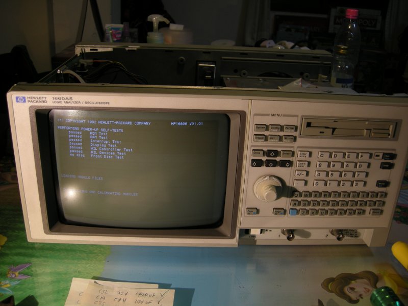


:phew:

Two weeks of repair finally over, learned a lot about power supplies in the process. Thanks for the help Toasty.
« Last Edit: September 13, 2021, 07:46:35 pm by modrobert »
 

Offline Toasty

  • Regular Contributor
  • *
  • Posts: 98
  • Country: us
  • Component Level Repair Tech
Re: HP 1660AS XL130-3604E PSU problem
« Reply #33 on: October 05, 2017, 07:04:11 pm »
 ;D

Good to see it working.  Lesson learned!  Check your work!

Best of luck!  :-+

T
veritas odium parit
 
The following users thanked this post: modrobert

Offline orin

  • Frequent Contributor
  • **
  • Posts: 445
  • Country: us
Re: HP 1660AS XL130-3604E PSU problem
« Reply #34 on: October 05, 2017, 08:11:29 pm »
The capacitors do like to leak and cause all manner of grief in these supplies.

On mine (from a 54510A), the electrolyte affected a crowbar circuit, so the PS would start up, then immediately shut down.  The scope would make a ticking sound.

You have to give the board a really good scrub before reinstalling/replacing capacitors.  I use a DMM on ohms and put one probe on a capacitor pad and drag the other probe around the board on the solder mask; _anywhere_ that shows a reading needs scrubbing.  Repeat for all unique (i.e. not connected to one already done) pads.  If the contamination goes under a component, then you have to unsolder the component, clean or replace it and clean underneath it too.  In my case, I had to clean under one of the trimpots.  It is surprising how far the electrolyte will spray across the board.

I used IPA from MG Chemicals for cleaning my board.  It seemed to be effective enough.
 

Offline modrobertTopic starter

  • Regular Contributor
  • *
  • Posts: 55
  • Country: th
Re: HP 1660AS XL130-3604E PSU problem
« Reply #35 on: July 08, 2018, 06:56:32 pm »
An update; had another problem with the same power supply (SMPS). The HP 1660AS scope/LA kept powering off sporadically, sometimes refusing to power on as well.

This time it was CR16, CR18, CR19, CR20 and CR21 zener diodes leaking too much current into the gate of A2 (C122F1) which is a reverse blocking thyristor in a "crowbar" configuration this resulted in reduced voltage on most rails except a few while A2 happily shorted 15.5V (VREF) rail to ground, also rendering A6 (LM339) useless with Vcc at 0.7V (it requires >3V).

What I did to fix this was lowering the resistance between A2 gate pin and ground from original 22 Ohm (R43) to 7 Ohm by adding another resistor between the cathode (ground) pin and gate pin of A2. Check the reversed schematics page 7 linked previously in this thread to understand what is going on.

EDIT:

Almost forgot, also had to remove S1 (MTS90A), the exotic curie effect over temperature switch reducing drive of the Q2 transistor (page 5 schematics). After desoldering to check S1 during first stages of analysing the problem it somehow got damaged, and now shorts to ground permanently, so it had to go, perhaps for the better, it couldn't take the heat in Bangkok. ;)
« Last Edit: July 08, 2018, 07:14:01 pm by modrobert »


Share me

Digg  Facebook  SlashDot  Delicious  Technorati  Twitter  Google  Yahoo
Smf