Author Topic: Keithley 2015 repair and the input buffer replacement.  (Read 13390 times)

0 Members and 1 Guest are viewing this topic.

Online Alex NikitinTopic starter

  • Super Contributor
  • ***
  • Posts: 1166
  • Country: gb
  • Femtoampnut and Tapehead.
    • A.N.T. Audio
Keithley 2015 repair and the input buffer replacement.
« on: December 20, 2015, 05:56:03 pm »
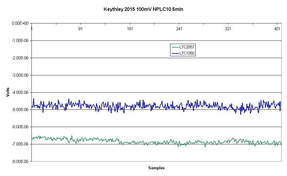
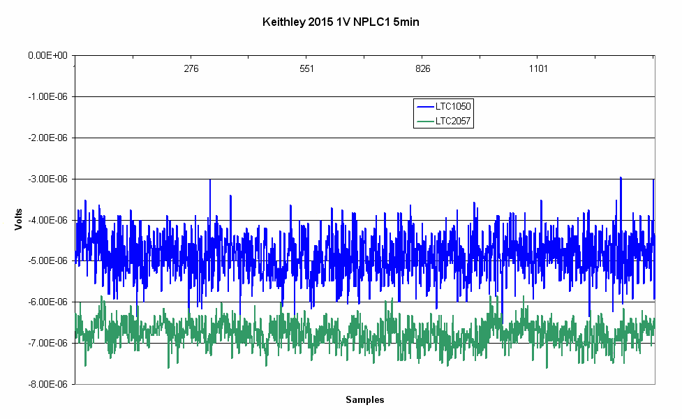
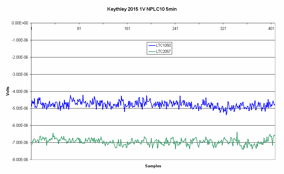
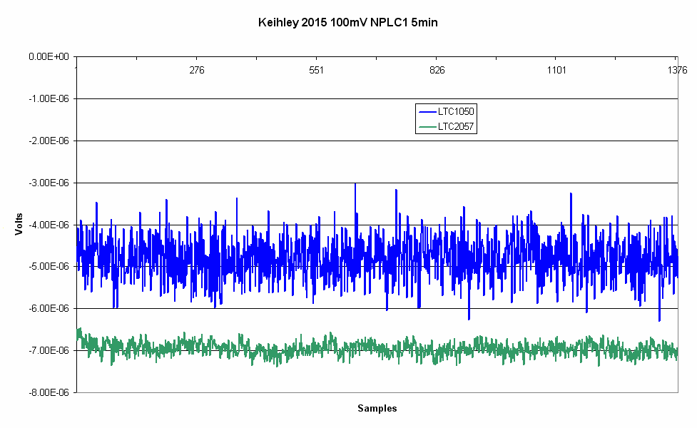
I have just finished repairing my two Keithley 2015. Both units did exhibit a very high input current in Volts mode. I've measured the input current on 10V range from -10V to +10V input, using the Keithley 617 electrometer. On the first unit the current varied from -50pA at -10V input to -1400pA at +10V input and about -670pA at 0V, the second was a bit better with +160pA at -10V, -300pA at 0V and -750pA at +10V.  As I could measure the input current directly, I've found very quickly that the excess current is due to leaking JFET switches, mostly Q114, Q136, Q138, Q139, Q120. To be on the safe side I've replaced additionally Q104-Q109, Q113. Also I've replaced the input buffer opamp (LTC1050) with LTC2057 on the first unit only. Now the unit #1 has input current +12pA at 0V, -120pA at +10V and +100pA at -10V, well within specs (< +/-200pA). The second unit with the original LTC1050 ended with -15pA at 0V, -95pA at +10V and -7pA at -10V. I did some noise measurements to compare two units - only 5min runs with a short on the input. There is little to no difference at NPLC0.1 on all ranges and for 10/100/1000V ranges at any NPLC setting, however for the 0.1V and 1V ranges there is a noticeable difference - see the graphs below.

Cheers

Alex


« Last Edit: December 20, 2015, 06:00:12 pm by Alex Nikitin »
 

Offline Smokey

  • Super Contributor
  • ***
  • Posts: 2572
  • Country: us
  • Not An Expert
Re: Keithley 2015 repair and the input buffer replacement.
« Reply #1 on: December 20, 2015, 06:06:57 pm »
What is the history of these units?  Ebay?

Do you think the extra input current was due to damage or just age?
 

Online Alex NikitinTopic starter

  • Super Contributor
  • ***
  • Posts: 1166
  • Country: gb
  • Femtoampnut and Tapehead.
    • A.N.T. Audio
Re: Keithley 2015 repair and the input buffer replacement.
« Reply #2 on: December 20, 2015, 06:13:58 pm »
What is the history of these units?  Ebay?

Do you think the extra input current was due to damage or just age?

Yes, I've bought both units on eBay a while ago, the first one in 2012 and the second in 2014, at about £250 each. It looks like that JFET damage is very typical for many Keithley meters from 2000 series. I knew that the input current is out of spec since I've bought them, however did not have time to fix it till now.

Cheers

Alex
 

Offline 3roomlab

  • Frequent Contributor
  • **
  • Posts: 825
  • Country: 00
Re: Keithley 2015 repair and the input buffer replacement.
« Reply #3 on: December 20, 2015, 06:27:15 pm »
nice! btw which JFET did you use to replace them? in my repair i used mmbf4393 (but it wasnt NXP, its the 35v fairchild variety)
i assume the LTC u are saying is U113 (my PCB has 2), the BJT power supply for zero buffer in mine were noisy, in longer 1NPLC log, you might want to check it esp when inside temp goes above 40oC (or at least thats what happen to mine  :-//)

*edit, i noticed 2 dips, it may be the popcorn thing i had before
**edit this is my current noise plot. it nolonger have dip/pops
« Last Edit: December 20, 2015, 06:41:53 pm by 3roomlab »
 

Online Alex NikitinTopic starter

  • Super Contributor
  • ***
  • Posts: 1166
  • Country: gb
  • Femtoampnut and Tapehead.
    • A.N.T. Audio
Re: Keithley 2015 repair and the input buffer replacement.
« Reply #4 on: December 20, 2015, 06:37:55 pm »
nice! btw which JFET did you use to replace them? in my repair i used mmbf4393 (but it wasnt NXP, its the 35v fairchild variety)

Yes, MMBF4393 is the right replacement, though I've used BF861 as I had these at hand (25V, similar capacitance, much lower resistance). I've ordered some MMBF4393 just in case the other ones would create a problem, however so far so good, everything works as it should (checked up to +12V input on 10V range). I plan to calibrate (DC only) these two over Christmas holidays, still need an accurate current source (10mA/100mA/1A) to do it.

Cheers

Alex
« Last Edit: December 20, 2015, 06:57:24 pm by Alex Nikitin »
 

Offline 3roomlab

  • Frequent Contributor
  • **
  • Posts: 825
  • Country: 00
Re: Keithley 2015 repair and the input buffer replacement.
« Reply #5 on: December 20, 2015, 06:43:38 pm »
ah self calibrate, well im still far from it, i hope i could do it. i wish you success, i need to learn how to do it :P
im sure the JFET vref you have made is now characterized as "helpers"?
(*edit in RS component i noticed NXP variant of mmbfJ111/mmbfJ112 to be similar and yet low noise, i am aiming to use those instead of 4393)
« Last Edit: December 20, 2015, 06:50:01 pm by 3roomlab »
 

Online Alex NikitinTopic starter

  • Super Contributor
  • ***
  • Posts: 1166
  • Country: gb
  • Femtoampnut and Tapehead.
    • A.N.T. Audio
Re: Keithley 2015 repair and the input buffer replacement.
« Reply #6 on: December 20, 2015, 06:55:48 pm »
(*edit in RS component i noticed NXP variant of mmbfJ111/mmbfJ112 to be similar and yet low noise, i am aiming to use those instead of 4393)

Don't. J111/112 have too large cut-off voltage, here the important parameters for the replacement (in the order of importance) - maximum voltage not less than 30V, cut-off voltage not more than 3V, low gate leakage, low ON resistance (original MMBF4393 JFETS measure about 70 Ohm, less is better if it does not sacrifice more important parameters), a similar input capacitance ~14pF . So out of J111/112/113 series only J113 may work. Voltage noise stated in the datasheet is not a problem here as the switch is either closed (so only the leakage is important) or open (only the channel resistance is important).

Cheers

Alex
« Last Edit: December 20, 2015, 07:01:13 pm by Alex Nikitin »
 

Offline 3roomlab

  • Frequent Contributor
  • **
  • Posts: 825
  • Country: 00
Re: Keithley 2015 repair and the input buffer replacement.
« Reply #7 on: December 20, 2015, 07:42:57 pm »
i see, thanks for tech tip. as a side note, does your Q120 turn on/off fully in ohms 2W mode? i asked cos i recorded mine to be having what appears to be stepped voltages (also because in my repair problem i suspect this to be a leak problem, still)
 

Online Alex NikitinTopic starter

  • Super Contributor
  • ***
  • Posts: 1166
  • Country: gb
  • Femtoampnut and Tapehead.
    • A.N.T. Audio
Re: Keithley 2015 repair and the input buffer replacement.
« Reply #8 on: December 20, 2015, 07:56:47 pm »
i see, thanks for tech tip. as a side note, does your Q120 turn on/off fully in ohms 2W mode? i asked cos i recorded mine to be having what appears to be stepped voltages (also because in my repair problem i suspect this to be a leak problem, still)

It works fine, and the open circuit voltage in Ohms mode is either 13V or 7V, depending on the range, that is perfectly normal.

Cheers

Alex
 

Offline 3roomlab

  • Frequent Contributor
  • **
  • Posts: 825
  • Country: 00
Re: Keithley 2015 repair and the input buffer replacement.
« Reply #9 on: December 20, 2015, 08:25:57 pm »
ok. i guess i leave these here in case anybody need a ref

gate voltage of Q119
in 2W mode, voltage of gate Q119 ref to TP102/AGND. [open circuit volts]

100R/1k : 6.33v
10k :6.47v
100k/1M : 14.92v
10M/100M : 6.47v

voltage CR114 cathode
100R/1k : 6.99v
10k :7.05v
100k/1M : 13.03v
10M/100M : 7.05v

voltage Q120 pin2/pin3
100R/1k : 6.73v/6.91 [6.9v/6.9v]
10k :6.80v/6.97 [6.9v]
100k/1M : 12.65v/12.51 [12.8v/12.8v]
10M/100M : 3.56v/-15.4 [7.0v/7.0v]

under keithley 2700 PDF, they describe the ohms range open circuit voltage
https://www.valuetronics.com/Manuals/KEITHLEY_2700.PDF

voltages added above
so at the time of this test, the 10M/100M range is faulty
« Last Edit: January 10, 2016, 05:56:21 pm by 3roomlab »
 

Offline Kleinstein

  • Super Contributor
  • ***
  • Posts: 14181
  • Country: de
Re: Keithley 2015 repair and the input buffer replacement.
« Reply #10 on: December 20, 2015, 09:32:15 pm »
On resistance of most of the JFETs is not that critical - even a 100 Ohms is still relatively low. Only Q114/Q136 are critical.

Leakage is relevant for the off mode: here the gate has a high bias (up to 30 V). In "On" mode the gate - source/drain voltage is close to zero, so leakage is low anyway.

Leakage can vary a lot - so an extra screening step before soldering could be a good idea, though tricky with SOT23 form.

There are also a few other parts that can contribute to bias: two OPs (AD822 or similar), the LTC1050 and possibly the optocoupler for the input protection if it is realy bad.
 

Offline 3roomlab

  • Frequent Contributor
  • **
  • Posts: 825
  • Country: 00
Re: Keithley 2015 repair and the input buffer replacement.
« Reply #11 on: December 21, 2015, 06:01:32 am »
following the JFET tips, could mmbf4093 be a better choice over 4394 ? it seem to be much better on leakage spec
 

Online Vgkid

  • Super Contributor
  • ***
  • Posts: 2710
  • Country: us
Re: Keithley 2015 repair and the input buffer replacement.
« Reply #12 on: December 21, 2015, 06:15:23 am »
Did you try using the to-18 canned 2n4393 Jfets. Since the gate is tied to the case, it might help with the noise.
If you own any North Hills Electronics gear, message me. L&N Fan
 

Offline 3roomlab

  • Frequent Contributor
  • **
  • Posts: 825
  • Country: 00
Re: Keithley 2015 repair and the input buffer replacement.
« Reply #13 on: December 21, 2015, 07:26:02 am »
i considered that, but i think it is too expensive to replace at that time (6pc x USD7?). at that point i have not much knowledge about the leakage/JFET.

now considering i have about 2nA bias/leak @ 7.5v. im not sure if this is normal. hence the consideration of 4093, which seem to have 1/5 the leak of 4393 but i might have read the spec wrong, as the 2 have slightly diff terms of leakage spec  :-DD ... i shall dig at the pdfs more
 

Online Alex NikitinTopic starter

  • Super Contributor
  • ***
  • Posts: 1166
  • Country: gb
  • Femtoampnut and Tapehead.
    • A.N.T. Audio
Re: Keithley 2015 repair and the input buffer replacement.
« Reply #14 on: December 21, 2015, 08:51:01 am »
following the JFET tips, could mmbf4093 be a better choice over 4394 ? it seem to be much better on leakage spec

It is almost the same thing as J111/112/113 (same process). The maximum cut-off voltage even for MMBF4093 is 5V, not good.

Cheers

Alex
 

Offline 3roomlab

  • Frequent Contributor
  • **
  • Posts: 825
  • Country: 00
Re: Keithley 2015 repair and the input buffer replacement.
« Reply #15 on: December 21, 2015, 10:01:23 am »
BF545 A/B ?
0.5pA leakage
last straw, no other JFETs from RS/E14 in my locality  :-DD
 

Online Alex NikitinTopic starter

  • Super Contributor
  • ***
  • Posts: 1166
  • Country: gb
  • Femtoampnut and Tapehead.
    • A.N.T. Audio
Re: Keithley 2015 repair and the input buffer replacement.
« Reply #16 on: December 21, 2015, 10:17:32 am »
BF545 A/B ?
0.5pA leakage
last straw, no other JFETs from RS/E14 in my locality  :-DD

Only BF545A, the "B" version may have too high cut-off voltage (unless you select them for less than 3V), and the ON resistance is too high  (200-300 Ohm) for the divider switching where two 70 ohm FETS in parallel used (Q114, Q136), and possibly also for Q109 and Q120 positions. Should be OK for the rest though.

Cheers

Alex
 

Offline TiN

  • Super Contributor
  • ***
  • Posts: 4543
  • Country: ua
    • xDevs.com
Re: Keithley 2015 repair and the input buffer replacement.
« Reply #17 on: December 26, 2015, 08:01:41 am »
How could I miss this thread?  :o
YouTube | Metrology IRC Chat room | Let's share T&M documentation? Upload! No upload limits for firmwares, photos, files.
 

Online Alex NikitinTopic starter

  • Super Contributor
  • ***
  • Posts: 1166
  • Country: gb
  • Femtoampnut and Tapehead.
    • A.N.T. Audio
Re: Keithley 2015 repair and the input buffer replacement.
« Reply #18 on: March 04, 2016, 07:03:37 pm »
After the repair and modification both units did show some obvious errors on 100V and 1000V ranges, so a calibration was required. It took me a while to get the DC ranges calibrated as I only had a 10V reference and didn't have another required 100V - or so I've thought. I had, actually a decent quality 100V output from my Keithley 617 electrometer - I've checked it's stability with 2015 meters and it has only drifted a couple of ppm over 10-15min after a good warm-up. But I needed to scale my 10V reference up to 100V - or at least measure 100V output from 617 with a good accuracy (say, at least 10ppm). Here is what I've done. A while ago I've bought on eBay a number of Vishay bulk foil resistors, quite cheaply as these were an odd value of 87.15K, with 0.01% stated tolerance. Actual deviation from the nominal value was much smaller - less than 20ppm. I've sorted resistors by measuring their relative value in 1-2ppm groups and selected ten to build an accurate 10:1 divider with a good stability and accuracy - better than 5ppm (actual error at the end was about +2...+3ppm). Using the Fluke 731B and a low thermal short I've calibrated both meters on DC steps 1-4 and saved the calibration results. Now I had meters reasonably accurate (hopefully under 10ppm) on 10V range. Next I've used one of the meters to measure the 100V output of the Keithley 617 with 6.5 digits resolution at the time of calibration of 100V range and did calibrate the second meter that way and than the other way around. Now all DC Volt ranges agree to one LSB error on both meters and the transfer accuracy of the Fluke hopefully gives me less than 10ppm error on 10V range (I've checked the 731B against a recently calibrated HP3458A Option2).

Here are some photos from that calibration evening.

Cheers

Alex

Both voltage sources:


Two 2015 meters, one measuring 102.4V output directly and another from the 10:1 divider:


The divider close up:

« Last Edit: March 04, 2016, 07:08:36 pm by Alex Nikitin »
 

Online Alex NikitinTopic starter

  • Super Contributor
  • ***
  • Posts: 1166
  • Country: gb
  • Femtoampnut and Tapehead.
    • A.N.T. Audio
Re: Keithley 2015 repair and the input buffer replacement.
« Reply #19 on: March 07, 2016, 06:17:38 pm »
Today, 10V from the Fluke 731B on both meters.

Cheers

Alex


Offline quarks

  • Frequent Contributor
  • **
  • Posts: 874
  • Country: de
Re: Keithley 2015 repair and the input buffer replacement.
« Reply #20 on: March 08, 2016, 04:53:30 am »
Nice repair job :-+
Thanks for sharing
 

Offline bdivi

  • Regular Contributor
  • *
  • Posts: 108
  • Country: bg
Re: Keithley 2015 repair and the input buffer replacement.
« Reply #21 on: March 09, 2016, 07:27:48 am »
Alex,

When you calibrated the units for Vdc did you need to also calibrate R and Idc or you managed to only calibrate voltage ?

I have 2015 that needs adjustment of the 100/1000Vdc ranges but I do not have a current source.

Thanks
 

Online Alex NikitinTopic starter

  • Super Contributor
  • ***
  • Posts: 1166
  • Country: gb
  • Femtoampnut and Tapehead.
    • A.N.T. Audio
Re: Keithley 2015 repair and the input buffer replacement.
« Reply #22 on: March 09, 2016, 08:58:32 am »
Alex,

When you calibrated the units for Vdc did you need to also calibrate R and Idc or you managed to only calibrate voltage ?

I have 2015 that needs adjustment of the 100/1000Vdc ranges but I do not have a current source.

Thanks

If you calibrate over GPIB it is possible to stop at DCV and save calibration constants. The calibration commands are described in the service manual (there is an obvious error in one of them for -10V - you need to specify "-10V", not "10V"). You calibrate DC steps 1 to 5 and then program calibration dates and save constants.

Cheers

Alex

P.S. - check for the input current in DCV 10V range first, if it is excessive you better change the JFETs, as it would affect 100/1000V ranges calibration.
« Last Edit: March 09, 2016, 09:01:21 am by Alex Nikitin »
 

Offline bdivi

  • Regular Contributor
  • *
  • Posts: 108
  • Country: bg
Re: Keithley 2015 repair and the input buffer replacement.
« Reply #23 on: March 09, 2016, 03:51:23 pm »
Too bad I do not have GPIB - I will have to think about voltage source and precision resistors in order to calibrate the current ranges.

BTW an easy way to check the leakage of the high impedance ranges is a standard 10M multi-meter in its lowest mV range used as a current shunt in series with the K2015 and to a 0-10V voltage source.  I used Fluke 187 which has 50mV range with 1uV resolution. That range divided by the 10M gives 0.1pA resolution.

My Keithley 2015 shows 80pA at 10V, 20pA at 0V and -100pA at -10V. I guess I am good here.
« Last Edit: March 09, 2016, 03:54:26 pm by bdivi »
 

Online Alex NikitinTopic starter

  • Super Contributor
  • ***
  • Posts: 1166
  • Country: gb
  • Femtoampnut and Tapehead.
    • A.N.T. Audio
Re: Keithley 2015 repair and the input buffer replacement.
« Reply #24 on: March 09, 2016, 04:30:38 pm »
Too bad I do not have GPIB - I will have to think about voltage source and precision resistors in order to calibrate the current ranges.

BTW an easy way to check the leakage of the high impedance ranges is a standard 10M multi-meter in its lowest mV range used as a current shunt in series with the K2015 and to a 0-10V voltage source.  I used Fluke 187 which has 50mV range with 1uV resolution. That range divided by the 10M gives 0.1pA resolution.

My Keithley 2015 shows 80pA at 10V, 20pA at 0V and -100pA at -10V. I guess I am good here.

You should be able to do a remote calibration over RS232, though I haven't tried it.

Cheers

Alex


Share me

Digg  Facebook  SlashDot  Delicious  Technorati  Twitter  Google  Yahoo
Smf