Author Topic: Quick repair project - Marconi 2024  (Read 46561 times)

0 Members and 1 Guest are viewing this topic.

Offline grumpydocTopic starter

  • Super Contributor
  • ***
  • Posts: 2905
  • Country: gb
Quick repair project - Marconi 2024
« on: September 29, 2012, 11:20:44 pm »
A while back there was some (slight) interest expressed in posting repair projects. The Rapco GPS conditioned oscillator repair which I described a few weeks ago seemed useful to a couple of people so I though I'd post details of another project.

In this case the item is arguably more interesting than the repair - a Marconi 2024 9kHz - 2.4GHz signal generator. This is basically the same signal generator as Dave's teardown in EEVBlog #261 but it has twice the frequency range. I picked it up on fleabay in need of a little TLC - the seller said it had "a weak display". This was his picture.


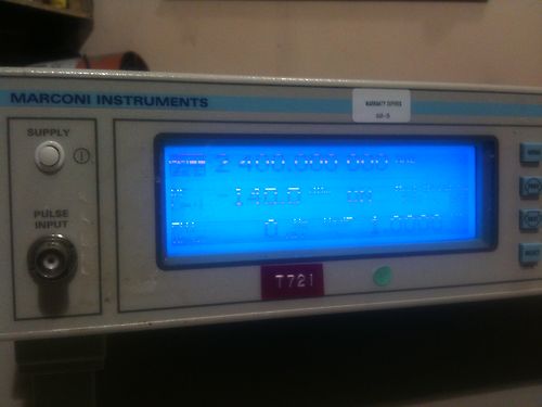
It looked like poor connections on the zebra strip in the LCD, an easy fix (I thought!) so I bought it.

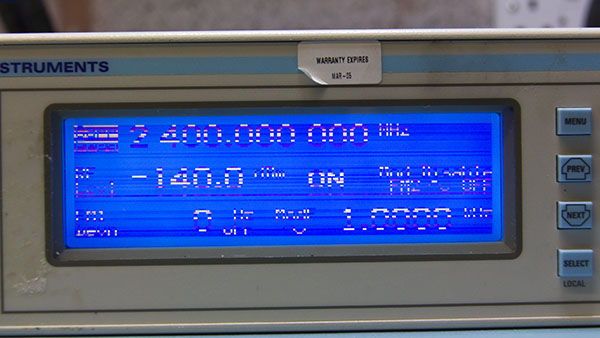
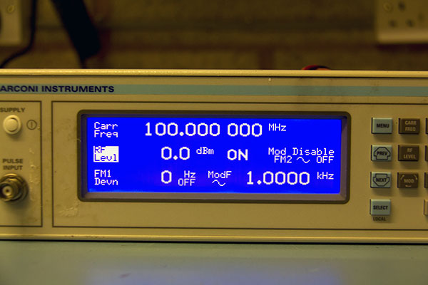
Ok, got it home and powered it up. The original description was certainly correct - the display was not happy. However it worked well enough for me to do a quick check of the generator and all seemed fine apart from the LCD which was good news. The generator was fitted with options 04 (OCXO) and 11 (pulse modulation and high +25dBm output).

After a while the display seemed to improve but it was still a bit difficult to read.

From here down click on the picture for a large version.


OK - time to crack it open :)


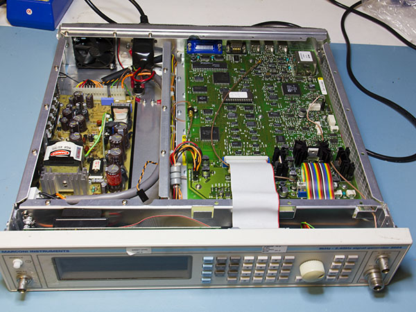
The first problem is that someone has been here first and not put the unit back together correctly - if you watch Dave's video there should be an aluminium plate screening the PSU. Ho Hum, at least they left the screws for me. Time to have a look for any more damage.

Hmmm, broken mains switch....


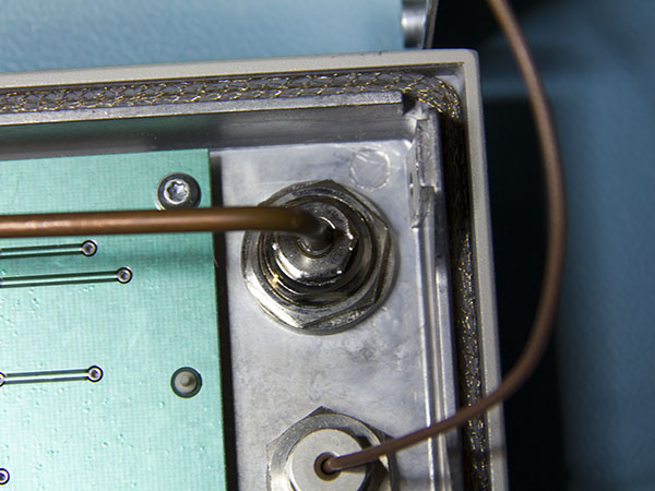
... and someone's "had a go" at the back of the N connector.....


... and there are only three screws holding the display in....


...but otherwise it doesn't look too bad.

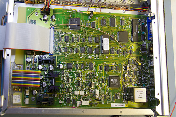
The main board is almost exactly as in Dave's teardown except for the OCXO in place of the TCXO in his 2023. Option 11 swaps out the attenuator unit for one with a higher power RF amplifier but that's hidden in the RF section. I'm not planning on opening that unless there's a clear need.


A closer look at the OCXO, it's an NDK unit but I can't find a datasheet anywhere for it.


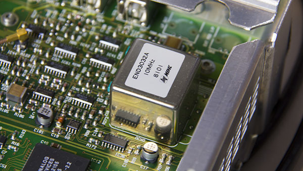
Looking at the date stamps on the various ICs and the stored calibration date it would appear to have been built in Feb 1998.

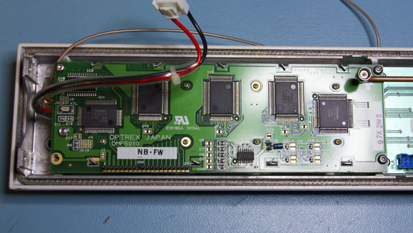
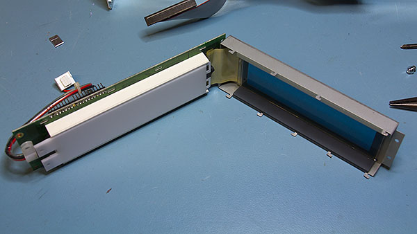
Moving on, to the LCD and I wasn't quite as happy as I had been. The problem seems to be the row drive connections as whole rows are not displayed or are not displaying correctly but, although there's a zebra strip (the grey block in the bottom right half of the display) it's only for the column connections. There's no zebra block for the row connectors but these use a flexible PCB strip.


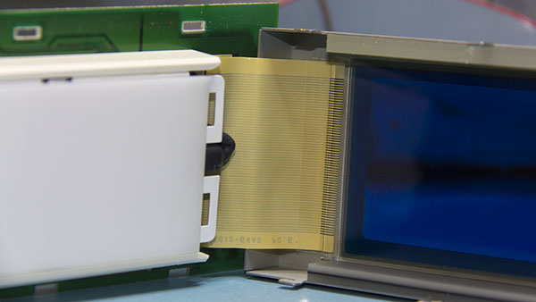
Here's a close-up of the connector. It's bonded to the PCB and to the LCD itself but it's clear that whatever I do is not going to improve the connections. I did try a bit of pressure against the PCB end up and down the actual contacts but it didn't make any difference.


At this point I was a bit hacked off with myself for buying the sig gen - I've looked for replacement LCDs without much luck for previous items, so I was a bit doubtful whether I could locate one for the Marconi. All too often equipment has a custom panel, however this looked generic - an Optrex DMF 5010 so I ploughed on into Google.

On the positive side I found a data sheet fairly easily. On the less good side there are few hits from suppliers - not even hits from the "we'll quote you anything" brokers. The only place I found with stock had a MOQ of 60 (which appeared to be the entire stock) - I might have considered it at the right price but £25 each before shipping and VAT wasn't the right price :( Even ebay couldn't help :o

More Googling and things brightened up a bit. The Optrex board has a T6963 controller so I figured if I could find a panel with the same resolution/display area and controller it might work - in the end I found one quite close to home at Rapid Online and not all that expensive.

It's not an exact match though, it has an LED backlight, not CCFL and it's smaller at 180mm rather than 200 and about 8mm less deep, but it has a compatible controller (the RA6963) and the same pin out so I though it was worth buying one.

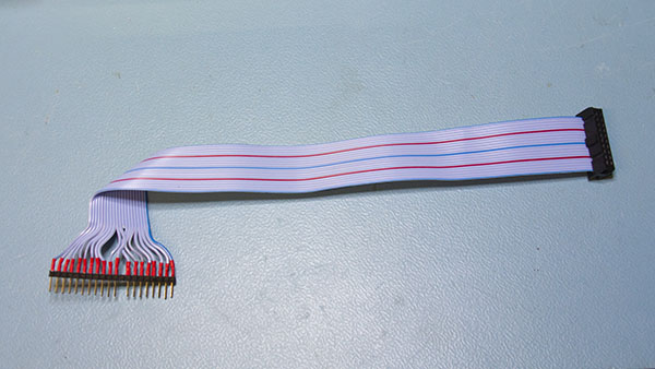
The first problem was to get it connected - the Winstar panel has a 2x10 pin connector, the Optrex one a 1x20. I didn't want to alter the original ribbon cable - generally if non-original parts need to be fitted I try to make things as "reversible" as possible so the plan was to use a piece of single row PCB header strip with ribbon cable soldered to make a plug to fit the cable IDC socket.


This didn't quite work as well as I'd hoped - the strip isn't really designed to have a cable soldered to it and even keeping soldering time to a minimum and the iron temperature as low as practical the pins almost immediately became loose. You can see in the photo that they're uneven. Fortunately it worked well enough without having to come up with another solution.

Next was the LED backlight supply. This turns out to be very easy as the CCFL inverter board is powered from 5V. The Winstar data sheet says that the LED has a VF of 3.5V and a forward current of 80mA, so with a 1.5V drop a 18ohm resistor should do nicely.

Connected it up and....
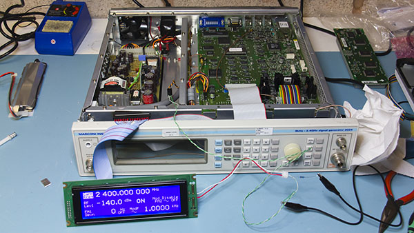
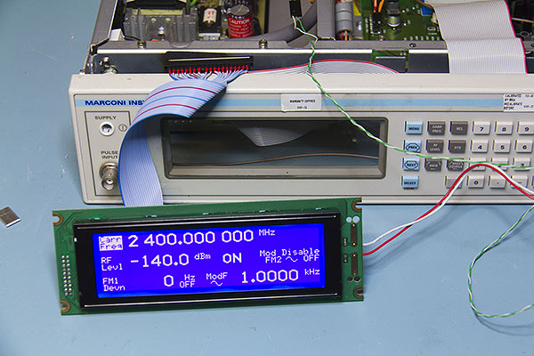


Bingo :) :) It works!!

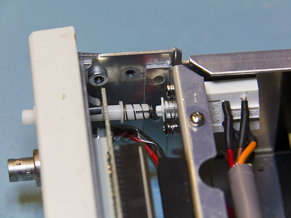
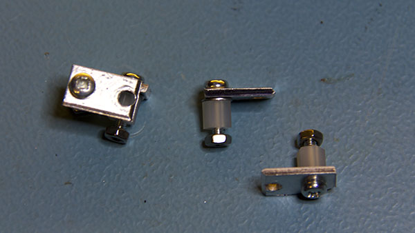
The next thing was to fix it in securely. I found some tiny aluminium plates, about 10x15mm in the junk box - absolutely no idea whether they had a purpose in life or were offcuts from something else but they were perfect to make small brackets to carry the new display. Two holes drilled 8.5mm apart to make up the horizontal difference and a 6mm threaded spacer to offset the panel a bit - here's what the result looks like.


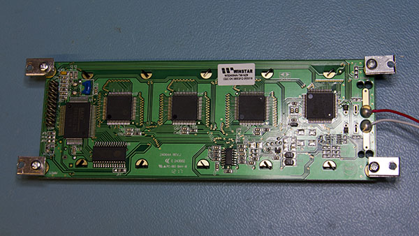
and here they are attached to the display ready to go into the front panel


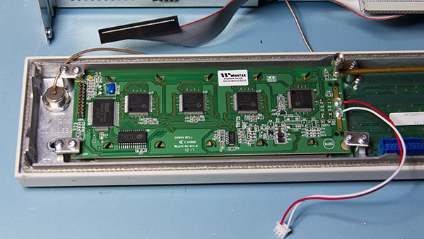
Finally here is the display mounted in the front panel and a shot of the new display in place.


The CCFL inverter board also carries the supply for the fan, decoupled with two 470uF electrolytics and two 1mH inductors so I still need to make up a small board to reproduce that and carry the current limiting resistor for the backlight LED. I also need to fix the mains switch but have some in the spares box so that's not a problem. All in all I'm very happy with the result and it's another piece of rescued test equipment.

It's slightly disappointing that it's already impossible to find components for an item that's not even 15 years old. Looking at some of the pictures in ebay auctions for 2023's and 2024's I note that quite a few have missing display lines, so this might be a common problem. It's nice to know that a newer LCD module can be adapted fairly easily to fit.

One other piece of good news regarding the 2023/2024 is that the service manual has just been uploaded to KO4BB's Manuals Repository. It's still in "Recent Uploads" but should be available for download fairly soon.
 
« Last Edit: May 02, 2013, 04:30:54 pm by grumpydoc »
 
The following users thanked this post: VK5RC, Zucca, feedback.loop, rodd, wolfy007, FransW, tonyalbus

Offline RCMR

  • Frequent Contributor
  • **
  • Posts: 405
Re: Quick repair project - Marconi 2024
« Reply #1 on: September 30, 2012, 01:28:20 am »
A tip -- when soldering cables to pin-headers in the way you did, plug the pinheader strip into a matching socket.  This will help sink the heat away and preserve the alignment (straightness) of the pins while soldering.
 
The following users thanked this post: Uunoctium

Offline SeanB

  • Super Contributor
  • ***
  • Posts: 16284
  • Country: za
Re: Quick repair project - Marconi 2024
« Reply #2 on: September 30, 2012, 05:56:17 am »
Tip for the mains switch is to look for an old XT tower case ( I know, really old but still a toss item) and use the power switch from it. Comes pre insulated, and with a 5 core cable with earth connector via a tag at both ends and insulated spade connectors on the PSU end.
 

Offline jeremy

  • Super Contributor
  • ***
  • Posts: 1079
  • Country: au
Re: Quick repair project - Marconi 2024
« Reply #3 on: September 30, 2012, 06:05:10 am »
This was cool! thanks for sharing
 

Offline muvideo

  • Frequent Contributor
  • **
  • Posts: 418
  • Country: it
Re: Quick repair project - Marconi 2024
« Reply #4 on: September 30, 2012, 08:13:14 am »
Interesting, thank you for documenting it.

As for the hotseal connector I've found that many times the problem is
where the connector is glued on the pcb. In the past I've "repaired" a few of them,
used a clean and round tipped soldering iron at 160°C, making a little pressure
on the adhesive connector where it is glued to pcb, moving the soldering
iron tip along the conductive strip, if you do this while the lcd is powered
you can see the line affected going on and off when you touch it.
But there is the risk is to damage the tape and once perforated no hope
to repair it anymore...

Fabio.
Fabio Eboli.
 

Online djsb

  • Frequent Contributor
  • **
  • Posts: 892
  • Country: gb
Re: Quick repair project - Marconi 2024
« Reply #5 on: September 30, 2012, 11:27:19 am »
Nice work.

David
David
Hertfordshire,UK
University Electronics Technician, London PIC,CCS C,Arduino,Kicad, Altium Designer,LPKF S103,S62 Operator, Electronics instructor. Give a man a fish and you feed him for a day. Teach a man to fish and you feed him for a lifetime. Credited Kicad French to English translator.
 

Offline grumpydocTopic starter

  • Super Contributor
  • ***
  • Posts: 2905
  • Country: gb
Re: Quick repair project - Marconi 2024
« Reply #6 on: September 30, 2012, 06:15:44 pm »
Quote
A tip -- when soldering cables to pin-headers in the way you did, plug the pinheader strip into a matching socket

Thanks - now you mention it that seems the most obvious thing to do and I'm kicking myself for not thinking of it.

Quote
In the past I've "repaired" a few of them, used a clean and round tipped soldering iron at 160°C, making a little pressure on the adhesive connector where it is glued to pcb

I'd applied a little heat (hot air gun set at 150°C) to the strip to see if I could get the adhesive to flow but, as I said, this didn't alter much at all. Because of the design of the display it's not possible to apply heat and monitor changes while it's powered up - the frame covers everything and needs to be closed for the zebra strip to make contact.

As for the LED supply I had intended to replace the whole of the original board but that would really need a PCB making up. Also I didn't have any high current 1mH inductors so I just took the CFL inverter module off and replaced it with a bit of stripboard with a connector and two 36ohm resistors in parallel - I wanted a bit more power rating than 1/4W as the dissipation was about 0.12W and a single 1/4W resistor was getting slightly too warm.

This is the original CCFL inverter/Fan PSU board


An post modification it now looks like this.


If necessary the inverter can easily be put back together with the connector.
 

Offline w2aew

  • Super Contributor
  • ***
  • Posts: 1780
  • Country: us
  • I usTa cuDnt speL enjinere, noW I aR wuN
    • My YouTube Channel
Re: Quick repair project - Marconi 2024
« Reply #7 on: September 30, 2012, 07:38:42 pm »
Nice retrofit repair!
YouTube channel: https://www.youtube.com/w2aew
FAE for Tektronix
Technical Coordinator for the ARRL Northern NJ Section
 

Offline reagle

  • Supporter
  • ****
  • Posts: 554
  • Country: us
    • KuzyaTech
Re: Quick repair project - Marconi 2024
« Reply #8 on: September 30, 2012, 11:25:42 pm »
Nice to see things put back in service with a bit of elbow grease ;)

Offline grumpydocTopic starter

  • Super Contributor
  • ***
  • Posts: 2905
  • Country: gb
Re: Quick repair project - Marconi 2024
« Reply #9 on: October 06, 2012, 05:04:24 pm »
Thanks for all the positive responses.

It turns out that the display wasn't quite the end of the story. I mentioned that I'd had a quick check to see if it worked but that only really covered whether it could generate a carrier. I hadn't tried getting a modulated carrier, when I did I was rewarded with less than comforting error messages such as "Fractional N loop too high" and "Amplitude modulator unlevelled" and no modulation.

A bit of fairly straightforward fault finding followed: there was no modulation but trying AM caused a fixed increase in output amplitude and in FM a fixed shift in frequency so it looked as though the modulation circuits were being fed DC but were, themselves, working. Trying external modulation worked so it looked as though the LF generator was the cause of the problem.

The modulation signal is generated by a DSP (overkill?) then goes through a 20kHz low pass filter and a couple more op-amp buffers, this is the circuit (click on image for full-sized version)


Everything is together in this area of the board by the OXCO, the DSP is a Analog devices ADSP-2105 with an AD1856 serial DAC, the op amps are a couple of SOIC TL074's


It was fairly easy to follow the signal through to find that IC207d was hosed, signal present on the input but nothing on the output. A quick replacement:


Not completely happy with the soldering but I'm still getting the hang of these SMD things (yes, I know SOIC hardly counts :)

Finally checking the output shows all is well.


Hopefully that's it, but the 2024 is complex enough that I still might find a bit that doesn't work, hopefully it will be not too difficult to fix if I do.

All I need to do now is figure out what the "level 2" password is so I can calibrate it - someone has kindly changed it from the default!
« Last Edit: October 06, 2012, 05:20:48 pm by grumpydoc »
 

Offline mianchen

  • Regular Contributor
  • *
  • Posts: 225
  • Country: gb
Re: Quick repair project - Marconi 2024
« Reply #10 on: October 06, 2012, 05:24:42 pm »
It's very impressive work! Well done.
 

Offline comprotudo

  • Newbie
  • Posts: 3
Marconi 2024 control knob
« Reply #11 on: May 02, 2013, 03:37:05 pm »
Hello,

I have also a 2024, witch a "little" problem.
When switch it on and activate the control knob to tune the frequency, level etc. he does not work, even I can see the under line, the values does not change.
After waiting a little I switch the generator on/off and everything work fine.
Does anyone have the same problem?
Any clue about that??

Regards
Rodrigo
 

Offline grumpydocTopic starter

  • Super Contributor
  • ***
  • Posts: 2905
  • Country: gb
Re: Quick repair project - Marconi 2024
« Reply #12 on: May 02, 2013, 04:29:23 pm »
Maybe the rotary encoder is unreliable.

One of the menus has an option to do a keyboard and encoder test, try that to make sure the encoder is working correctly.
 

Offline comprotudo

  • Newbie
  • Posts: 3
Re: Quick repair project - Marconi 2024
« Reply #13 on: May 08, 2013, 02:45:17 pm »
I have checked that. When it runs ok I'm able to check the rotary encoder.
When it fails at beginning, the rotary check fail.
Probably the generator makes a initial check and some times he can't "see" the encoder.
I need some one can confirm this fact.

Rodrigo


Maybe the rotary encoder is unreliable.

One of the menus has an option to do a keyboard and encoder test, try that to make sure the encoder is working correctly.
 

Offline grumpydocTopic starter

  • Super Contributor
  • ***
  • Posts: 2905
  • Country: gb
Re: Quick repair project - Marconi 2024
« Reply #14 on: January 19, 2014, 12:05:11 am »
To continue an old thread..........

The Marconi had been behaving itself nicely for quite some time but it looks like it wants to attract some attention to itself.

I was using it for some bandwidth/frequency response checks on a 'scope I've just repaired and tried to dial up a 20MHz output only to be greeted with


and no output either - rats!  :-BROKE

Some fiddling later I noticed that it's only lost output from 18.75MHz through to 37.5MHz, everything else is fine, so checking the service manual I noticed this in the description of the error


OK, that looks promising in terms of narrowing it down, lets have a look at the schematic. The band pass filters seem to use steering diodes to switch themselves in and out of the signal path.


Click on the image above for the full circuit diagram of this section.

So it looks like SW9 is the switching voltage point - that comes from here


I had to reduce that a bit so it's slightly hard to read - again you can click on the image for the full sized one. Basically two 74HC138's are used to form a one of 16 decoder and then three LM324's are used as comparators/level shifters to drive the filter sections. One thing which does seem odd is that SW10 has two comparators driving it (IC604a and IC606b) as does SW1 (IC604c & d) but the others just have one comparator. Absolutely no idea why they did that

I'm really hoping that one of the 74HC138's outputs has died - or the comparator. If not I'm stuck, the only other active components are the steering diodes (which I suppose it could be). After that I can't see any of the inductors or caps in the filter section suddenly keeling over.

It's a bit late to open up the RF section and start looking so that will have to wait until tomorrow but I'll report back. In the meantime - thoughts anyone?
 
The following users thanked this post: feedback.loop

Offline Jay_Diddy_B

  • Super Contributor
  • ***
  • Posts: 2733
  • Country: ca
Re: Quick repair project - Marconi 2024
« Reply #15 on: January 19, 2014, 12:59:22 am »
Hi,

The LM324 have been put in parallel for the SW10 drive to increase the current to diode switches.

The LM324 simple shifts the 0-5V output from the 74HC138 to +5V or -11V for the pin diode switches.

SW10 should negative if the 18.75 to 37.5 MHz band is selected.

How to troubleshoot will depend if you can get good access to this board with unit running. If you can access the components you can follow the signal through the filter assembly with a scope.

Regards,

Jay_Diddy_B
 

Offline G0HZU

  • Super Contributor
  • ***
  • Posts: 3015
  • Country: gb
Re: Quick repair project - Marconi 2024
« Reply #16 on: January 19, 2014, 01:08:37 am »
Quote
All I need to do now is figure out what the "level 2" password is so I can calibrate it - someone has kindly changed it from the default!

I bought one of these generators a few years ago and had the same issue with the level 2 password. I overcame this by contacting IFR UK and they gave me contact details for someone in the USA.

I phoned him up at a prearranged time and gave him the S/N of the sig gen and he quickly gave me the 'hard' unlock code for level 2 for my generator.

i.e. there are two level 2 password codes. One you can change yourself and one that is hard coded (but unique to each generator). So once I had the hard code I could unlock and then set my level 2 code back to the default. Hope this helps :)
« Last Edit: January 19, 2014, 01:10:51 am by G0HZU »
 

Offline grumpydocTopic starter

  • Super Contributor
  • ***
  • Posts: 2905
  • Country: gb
Re: Quick repair project - Marconi 2024
« Reply #17 on: January 19, 2014, 09:20:42 am »
Quote from: G0HZU
I bought one of these generators a few years ago and had the same issue with the level 2 password. I overcame this by contacting IFR UK and they gave me contact details for someone in the USA.

I phoned him up at a prearranged time and gave him the S/N of the sig gen and he quickly gave me the 'hard' unlock code for level 2 for my generator.

i.e. there are two level 2 password codes. One you can change yourself and one that is hard coded (but unique to each generator). So once I had the hard code I could unlock and then set my level 2 code back to the default. Hope this helps :)
Yes, I heard the same and tried contacting Aeroflex to see if I could get the code but no luck. In the end I wound up sniffing the reads from the EEPROM to figure it out.

Quote from: Jay_Diddy_B
The LM324 have been put in parallel for the SW10 drive to increase the current to diode switches.
Yes, I wondered if that was the case, but why on only two of the switches? It's only SW10 and SW1 which have the doubled up drive.

Quote from: Jay_Diddy_B
The LM324 simple shifts the 0-5V output from the 74HC138 to +5V or -11V for the pin diode switches.
Yes, that was fairly obvious - I mentioned it in my post.

Quote from: Jay_Diddy_B
SW10 should negative if the 18.75 to 37.5 MHz band is selected.

I'm pretty certain it's SW9. In another table in the manual it confirms the select codes for the various low pass filters which are:

Table 1-4: Frequency band selection
BS3BS3BS2BS0Selected Band
0000420 - 600 MHz
0001300 - 420 MHz
0010150 - 300 MHz
010075 - 150 MHz
011037.5 - 75 MHz
100018.75 - 37.5 MHz
101010 - 18.75 MHz
11001.2 - 2.51 GHz
11100.84 -1.2 GHz
1111600 - 840 MHz

The code for the 18.75 - 37.5MHz band is 8, the description in the manual mentions that the codes are chosen so that the same control bits are used to control the division ratio of IC602. If you follow the 8th select line (Y0 on the 2nd HC138 - IC603), highlighted in yellow on the snippet of schematic that I posted, it drives SW9 which also looks to be the right switching point in the LPF section. I'll check, though, when I get it open later today.

Quote from: Jay_Diddy_B
How to troubleshoot will depend if you can get good access to this board with unit running. If you can access the components you can follow the signal through the filter assembly with a scope.

Yes - actually it looks pretty easy. Dave did a teardown of a 2023 which is basically identical to the 2024, if you look at around 27:02 you can see the frequency generator section and the two HC138's and three LM324's clearly, just above the divide-by-n chip which Dave points out. Access for testing should be fine, depending on whether it is IC604 or IC606 I might have to remove the diecast internal screening to get a soldering iron/hot air in.

https://www.youtube.com/watch?feature=player_detailpage&v=Gmryy5KWm_g#t=1622
« Last Edit: January 19, 2014, 02:10:22 pm by grumpydoc »
 

Offline G0HZU

  • Super Contributor
  • ***
  • Posts: 3015
  • Country: gb
Re: Quick repair project - Marconi 2024
« Reply #18 on: January 19, 2014, 01:45:40 pm »
I'd be tempted to (initially) troubleshoot this circuit by looking at the bias voltages and currents  rather than to try and trace an RF signal through it.

If any series component in the chosen RF path fails open circuit then the bias chain will be broken and it should be easy to work out where the break is.

Something doesn't look right around D647,  D619 and D618 so I'm not sure I trust the circuit here. Is there something missing from the circuit here? eg a bias feed? Or is D647 drawn backwards?

If the bottom series diode path is unbroken then I think there should be something like 4V dropped across R603. However, these are just guesses based on the circuit diagram in the service manual.

It looks like the top series diodes are only weakly biased at maybe 600uA but the bottom section of series diodes is biased at maybe 8mA. Quite a difference? Is there a mistake in the schematic around D647 as mentioned above?

The reason SW1 is doubled up is because it has to drive three parallel diodes in forward bias. If Vcc = 5V and there's 1.5V dropped in the LM324 then the bias current for each opamp will be (5-1.5-0.7)/274R = 10mA each. So the total forward bias into the diodes will be 10+10 = 20mA (about 7mA each diode?).

I'm not sure why SW10 is doubled up. Maybe they did it because it was there as an unused opamp in the quad LM324 package? So they just used it as it was free?

I did spot a typo in the 37.5MHz LPF. L635 should be 330n (or maybe even 270n) and not 330m.

If I had to guess where the fault was I'd say it was a poor soldered connection under L633, L634, L635 or L636.

« Last Edit: January 19, 2014, 04:06:54 pm by G0HZU »
 

Offline G0HZU

  • Super Contributor
  • ***
  • Posts: 3015
  • Country: gb
Re: Quick repair project - Marconi 2024
« Reply #19 on: January 19, 2014, 02:10:58 pm »
I'm pretty sure D647 is drawn backwards and if this is corrected then the whole bias system makes sense because the bias current in the top section will be several mA (biased from R602 up near the top LH corner of the full schematic)

So the whole circuit will be more balanced in terms of bias at around 5mA for both top an bottom :)

Doubling up SW10 on the 18.75MHz range will increase this bias by a couple of mA. Not sure why they are doing this but maybe this reduces the RF loss slightly. Seems odd to do this on the lowest frequency range...

« Last Edit: January 19, 2014, 02:31:49 pm by G0HZU »
 

Offline grumpydocTopic starter

  • Super Contributor
  • ***
  • Posts: 2905
  • Country: gb
Re: Quick repair project - Marconi 2024
« Reply #20 on: January 19, 2014, 05:35:20 pm »
Thanks for your analysis - it far exceeds my understanding of what's going on!.

Quote from: G0HZU
I'd be tempted to (initially) troubleshoot this circuit by looking at the bias voltages and currents  rather than to try and trace an RF signal through it.

Agree, there's really no point tracing the RF if the switching voltages aren't present andit's easy enough to chek these.

Quote from: G0HZU
If I had to guess where the fault was I'd say it was a poor soldered connection under L633, L634, L635 or L636.

I'd be slightly surprised if this were the case - I'd expect a dodgy soldered joint to be intermittent before (even if) it failed completely.

Anyway - I've now had the chance to have a look. Unlike Dave's I just get standard mild steel torx screws, not sexy black ones. There are a lot of them though :)
Click on any pic for a larger version.


I almost wonder whether the screws in Dave's were the correct ones  - he mentioned his puzzlement at the fact that the cutouts in the aluminium above each screw weren't quite big enough to let the screw out unless he slid the whole tray out a bit. The cutouts are fine with the smaller head of the torx.

OK, we're in  ;D Looks like the rubber gaskets in mine want to stay stuck to the aluminium plate, not in the slots that they are supposed to go in.The area of interest is the lower left corner.


Visual inspection is OK except I'm not sure I like what's going on around IC605, that looks a bit odd.


Taking a closer look reveals that I'm not the first to come by here - it looks as though IC605 has already been replaced and no real attempt to clear the flux away has been made.


I can clean that later, for now it only took a couple of quick measurements to confirm that the Y0 output of IC603 isn't pulling down to logic 0 when I select a frequency between 18.75 and 37.5MHZ - it sort of makes a limp attempt but only gets from just under 5V to about 3.

Whether that's a problem with the HC138 or the LM324 I don't yet know but I'm pretty certain that I don't have any 324's lying around and equally sure I should be able to find an HC138

Off to hunt in the parts bin.
 

Offline grumpydocTopic starter

  • Super Contributor
  • ***
  • Posts: 2905
  • Country: gb
Re: Quick repair project - Marconi 2024
« Reply #21 on: January 19, 2014, 07:21:13 pm »
I'm pretty sure D647 is drawn backwards and if this is corrected then the whole bias system makes sense because the bias current in the top section will be several mA (biased from R602 up near the top LH corner of the full schematic)

So the whole circuit will be more balanced in terms of bias at around 5mA for both top an bottom :)

Doubling up SW10 on the 18.75MHz range will increase this bias by a couple of mA. Not sure why they are doing this but maybe this reduces the RF loss slightly. Seems odd to do this on the lowest frequency range...

I think you're right, here's the PCB:


D618 and D619 are the two vertical diodes in the centre. The cathodes are marked for most diodes on the silkscreen and these two are joined anode to anode as on the schematic.

D647 must be the unlabelled horizontal diode in the centre of the picture  - its cathode is connected to the junction of D618 and D619, not its anode as shown in the diagram so I think that you're spot on in your diagnosis.
 

Offline peter-h

  • Super Contributor
  • ***
  • Posts: 3697
  • Country: gb
  • Doing electronics since the 1960s...
Re: Quick repair project - Marconi 2024
« Reply #22 on: February 24, 2014, 04:12:15 pm »
This has been a very interesting read - especially as I am about to buy one of these (2023 or 2024). I need something fairly portable and at about 8kg these units are unusual. Many thanks for documenting it.

That circuit with the 3 diodes was obviously wrong because there is no way to get any current to flow through the middle node!

The other thing which is readily apparent is that if you buy one of these and it stops working, it is rather likely that it will have to be scrapped unless the service manuals are available. I have an old HP 3314A low frequency signal generator which uses a load of reed switches and I've had to replace a number of them, but (a) I did get the service manual with it; (b) usually it is obvious that one of them has gone; (c) they are easy to fix. The microprocessor control side of it (TMS9900!) would be impossible to fix unless it is something really obvious.

How does one get the service manual?

The other Q I have is: where can one buy handles? The units I see for sale (at a reasonable price) don't come with them. I can machine some up but it would be easier to buy something...
« Last Edit: February 24, 2014, 04:20:44 pm by peter-h »
Z80 Z180 Z280 Z8 S8 8031 8051 H8/300 H8/500 80x86 90S1200 32F417
 

Offline grumpydocTopic starter

  • Super Contributor
  • ***
  • Posts: 2905
  • Country: gb
Re: Quick repair project - Marconi 2024
« Reply #23 on: February 24, 2014, 05:08:36 pm »
Quote
How does one get the service manual?

Ko4bb has them for download - link in reply #14

As to handles - I've seen a few units for sale with them fitted but haven't seen any handles for sale by themselves.
 

Offline G0HZU

  • Super Contributor
  • ***
  • Posts: 3015
  • Country: gb
Re: Quick repair project - Marconi 2024
« Reply #24 on: February 24, 2014, 09:16:57 pm »
Quote
That circuit with the 3 diodes was obviously wrong because there is no way to get any current to flow through the middle node!
Agreed. However, I have learned from bitter experience to avoid saying (on a forum) that a manufacturer has 'definitely' made a mistake in their documentation. People reading the thread can get upset or annoyed and I end up getting slated for pretending to know better than the manufacturer. :)

As for the handles, I would not bother buying any. They do provide a degree of protection for the front panel but they often break. I think what happens is that they age and weaken due to knocks and stress and eventually someone will pick up the generator by just one of these handles and the handle will snap. I think this is one reason why these generators get damaged internally as they suffer impact damage.

At work we have dozens of them and quite a few of them are missing one or both handles. Sometimes there's half a handle still fitted after it has broken off.


« Last Edit: February 24, 2014, 09:20:43 pm by G0HZU »
 

Offline peter-h

  • Super Contributor
  • ***
  • Posts: 3697
  • Country: gb
  • Doing electronics since the 1960s...
Re: Quick repair project - Marconi 2024
« Reply #25 on: February 24, 2014, 09:22:47 pm »
I will machine some up from ~ 3mm aluminium. I didn't realise they were plastic. On a ~ $8000 (new price) box that's not good.
Z80 Z180 Z280 Z8 S8 8031 8051 H8/300 H8/500 80x86 90S1200 32F417
 

Offline G0HZU

  • Super Contributor
  • ***
  • Posts: 3015
  • Country: gb
Re: Quick repair project - Marconi 2024
« Reply #26 on: February 24, 2014, 09:32:20 pm »
Yes, they are just cheap plastic handles. Not good at all.

I did a quick google and found an image of a broken one. This is what they usually look like after someone has either dropped it on the handle or the handle snapped as they were carrying it.
 

Offline G0HZU

  • Super Contributor
  • ***
  • Posts: 3015
  • Country: gb
Re: Quick repair project - Marconi 2024
« Reply #27 on: February 24, 2014, 09:41:50 pm »
They are very good generators though... The frequency plan inside lends itself to achieving very low phase noise over most of the generator's range. This is because of the multi VCO + divider+ multiplier system they use. I've measured the phase noise on quite a few of the ones at work and they are always very good on the lower ranges.

I have one myself here at home with option 4 and 11 fitted and I've done quite a few performance tests on it. The quality of the internal modulation is excellent. Much, much lower distortion than the spec sheet suggests.

The user interface can be a bit fiddly and annoying but the performance makes up for this. The only thing that really bugs me about this one is the fan noise is quite annoying in a quiet room. I'm not sure if it has a beefier fan for the options fitted as I don't notice the fan on the ones at work. But they don't have these options fitted. it only had 120hours' use on it when I bought it and there was no dust inside so I don't think the fan is noisy due to wear.
 

Offline peter-h

  • Super Contributor
  • ***
  • Posts: 3697
  • Country: gb
  • Doing electronics since the 1960s...
Re: Quick repair project - Marconi 2024
« Reply #28 on: February 24, 2014, 09:48:24 pm »
I have looked for one with Option 4 but (here in the UK) they cost about 70% more.

Option 4 brings it up to the stability spec of the 2030 which is a much bigger unit, albeit oddly enough a lot cheaper when looking on Ebay.

I don't actually need the extra spec though.

IFR make a lot of avionics test gear and you need good quality modulation for that - e.g. the 90/150Hz ILS modulation needs to be closely depth-matched, to something like 1%. And Marconi before them did a lot of that stuff too. So maybe they designed it with that in mind. Certainly the 2030 is heavily pushed by their marketing stuff into that market.

Noisy fans are a real hassle and on non-warranty units I tend to replace them with SAN ACE fans, 12V ones powered from 5V :) Very silent  ;D
Z80 Z180 Z280 Z8 S8 8031 8051 H8/300 H8/500 80x86 90S1200 32F417
 

Offline G0HZU

  • Super Contributor
  • ***
  • Posts: 3015
  • Country: gb
Re: Quick repair project - Marconi 2024
« Reply #29 on: February 24, 2014, 09:58:38 pm »
I might see if it's possible to fit an alternative fan :)
Here's a plot of the phase noise of one of the units at work. It had an odd blip in the phase noise at a couple of kHz and the E5052A found it.

If you ignore the strange blip, the phase noise at 28MHz is pretty decent for a mid range generator. I have a library of phase noise plots at work of all the various generator models we have. They all get measured on the E5052A at about 12 points in their frequency coverage and it is a useful reference.

I've added another plot of the phase noise at the top frequency 2400MHz and the little blip is still there. When I took these plots a year or so ago the blip was only there on this particular example.
« Last Edit: February 24, 2014, 10:07:46 pm by G0HZU »
 
The following users thanked this post: harha

Offline grumpydocTopic starter

  • Super Contributor
  • ***
  • Posts: 2905
  • Country: gb
Re: Quick repair project - Marconi 2024
« Reply #30 on: February 24, 2014, 10:43:15 pm »
Quote
I have looked for one with Option 4 but (here in the UK) they cost about 70% more.

Option 4 brings it up to the stability spec of the 2030 which is a much bigger unit, albeit oddly enough a lot cheaper when looking on Ebay.

I got lucky and mine has the OCXO. It would probably be possible to fit an ovened oscillator fairly easily - the one in mine is an NDK unit. I thought  someone had posted a llink to the datasheet but can't find it now.
 

Offline peter-h

  • Super Contributor
  • ***
  • Posts: 3697
  • Country: gb
  • Doing electronics since the 1960s...
Re: Quick repair project - Marconi 2024
« Reply #31 on: February 25, 2014, 09:38:37 am »
Is the oven the only difference?

They take quite a while to warm up and you get loads of drift during that time. Many years ago I was designing precision HV power supplies and we were aiming to get the reference to a few ppm per degC. I don't recall the device we used but it was a TO5 case and was in a 90 degC oven which used a lot of power. The oven heater was implemented as a PTC thermistor so it warmed up and just sat there. Now you can get 1ppm/degC for a fiver, in a SO-8 :)
Z80 Z180 Z280 Z8 S8 8031 8051 H8/300 H8/500 80x86 90S1200 32F417
 

Offline grumpydocTopic starter

  • Super Contributor
  • ***
  • Posts: 2905
  • Country: gb
Re: Quick repair project - Marconi 2024
« Reply #32 on: February 25, 2014, 10:41:21 am »
Quote
Is the oven the only difference?

As far as I know.

The one in mine is an NDK END3032A (see photos earlier in the thread). If anyone does have adatasheet it would be handy.

There's one for sale on the dutch ebay.
 

Offline peter-h

  • Super Contributor
  • ***
  • Posts: 3697
  • Country: gb
  • Doing electronics since the 1960s...
Re: Quick repair project - Marconi 2024
« Reply #33 on: February 25, 2014, 11:22:41 am »
There is a pile of 10MHz OXCOs on Ebay - all relatively dirt cheap e.g. item # 300861292471.

Or, working on the basis of going for the biggest and most expensive, if you wanted one which has already had 18 years of ageing you could got for item # 111271809705 :)

Would the Dutch one actually fit directly into a 2024, with no config changes etc?
« Last Edit: February 25, 2014, 11:26:11 am by peter-h »
Z80 Z180 Z280 Z8 S8 8031 8051 H8/300 H8/500 80x86 90S1200 32F417
 

Offline grumpydocTopic starter

  • Super Contributor
  • ***
  • Posts: 2905
  • Country: gb
Re: Quick repair project - Marconi 2024
« Reply #34 on: February 25, 2014, 11:34:52 am »
Quote
Would the Dutch one actually fit directly into a 2024, with no config changes etc?

I don't have access to ebay at work but while having another google trawl last night to see if I could find a datasheet for the NDK OXCO found an auction for one attached to a PCB (possibly from a 2026). As it's the same OCXO as in my 2024 it should drop straight in**.

Obviously you would need to re-run the OCXO cal because the control voltage will need to change.

** OK you need to remove the CPU board to take out the old TCXO and solder in the new OCXO but you know what I mean :)

 
The following users thanked this post: Chris56000

Offline peter-h

  • Super Contributor
  • ***
  • Posts: 3697
  • Country: gb
  • Doing electronics since the 1960s...
Re: Quick repair project - Marconi 2024
« Reply #35 on: March 04, 2014, 08:01:09 pm »
I bought that Ebay OCXO...

I will keep it in case it is needed later.

I also collected the 2024 today. A very nice piece of gear.
Z80 Z180 Z280 Z8 S8 8031 8051 H8/300 H8/500 80x86 90S1200 32F417
 

Offline G0HZU

  • Super Contributor
  • ***
  • Posts: 3015
  • Country: gb
Re: Quick repair project - Marconi 2024
« Reply #36 on: March 04, 2014, 09:41:28 pm »
Some time ago I logged the warmup profile of my 2024 with the HS OCXO option (it has options 4 and 11)


It takes about 5 minutes to get to a decent level of accuracy. Not bad and much quicker than some OCXOs.
I've attached the raw text file below.

The first column is time in seconds and the second is frequency measured by an Anritsu frequency counter and logged onto a netbook PC via USB/GPIB.


Offline G0HZU

  • Super Contributor
  • ***
  • Posts: 3015
  • Country: gb
Re: Quick repair project - Marconi 2024
« Reply #37 on: March 04, 2014, 09:48:35 pm »
I also logged the amplitude flatness via GPIB with two power meters I have here.

One is an old HP431C/HP478A thermistor type power meter from about 50 years ago and the other is a more modern Anritsu thermocouple type.
The meters agree quite well and the ripple is definitely in the 2024. Not a particularly spectacular performance for flatness but more than acceptable :)

Note: the zigzaggy fuzzy noise on the traces isn't noise. It's the 2024. It has a regular fine sawtooth response in the level of about 0.02dB. The old analogue HP431C meter picks this up really well but the Anritsu can only give 0.01dB resolution over its GPIB interface so it looks grainier.


« Last Edit: March 04, 2014, 09:54:46 pm by G0HZU »
 
The following users thanked this post: harha

Offline peter-h

  • Super Contributor
  • ***
  • Posts: 3697
  • Country: gb
  • Doing electronics since the 1960s...
Re: Quick repair project - Marconi 2024
« Reply #38 on: March 04, 2014, 10:21:24 pm »
It must be extremely difficult to achieve flat output power (voltage into 50 ohms) over that frequency range. They use every trick in the book to avoid using a large number of reed relays and are having to linearise various bits of the attenuator. Somebody must have spent ages getting that circuitry to work right.
Z80 Z180 Z280 Z8 S8 8031 8051 H8/300 H8/500 80x86 90S1200 32F417
 

Offline G0HZU

  • Super Contributor
  • ***
  • Posts: 3015
  • Country: gb
Re: Quick repair project - Marconi 2024
« Reply #39 on: March 04, 2014, 11:10:18 pm »
I have to disagree a bit on the levelling performance :) I would class the levelling performance as more than adequate for most users but I think it lets the rest of the generator down a bit.

I think the levelling circuit is based on a low cost, low parts count peak detector + ALC system and the ripply performance in my tests shows that this generator isn't really lab grade in this respect. Maybe mine's a bad example but the detector/levelling circuit looks pretty basic to me in the  manual and there aren't many calibration points to make up for its detector and attenuator/path flatness. I expected slightly better performance from Marconi here, especially in the 10-800MHz region.

What is amazing to me is the performance of the old HP431C power meter. I have had this old power meter since the mid 1990s and I have never adjusted/calibrated it in 15-20 years. Unlike newer thermocouple meters it's a fully closed loop system and it just seems to stay accurate year after year :)


« Last Edit: March 04, 2014, 11:18:24 pm by G0HZU »
 

Offline peter-h

  • Super Contributor
  • ***
  • Posts: 3697
  • Country: gb
  • Doing electronics since the 1960s...
Re: Quick repair project - Marconi 2024
« Reply #40 on: March 05, 2014, 08:20:19 am »
Some of the old kit was very good.

Yesterday, when I collected the 2024 and an Artitsu 2661 spectrum analyser, I tested a 1980s HP DVM (6.5 digit - bought it for £100 in 1998) against a £50k Fluke calibrator they have. The DVM was under-reading by 0.006% (60ppm).

Funnily enough I also tested a 5V reference I built with a Maxim £5 "5V 0.02%" voltage reference chip. That was within 0.001% of the Fluke calibrator.

I wonder why Marconi didn't use a simple resistive attenuator, with 20p MOSFETs doing the resistor switching? Maybe the parasitic capacitances at GHz frequencies make that a problem. Nowadays, this
http://www.psemi.com/content/products/productSubCat.php?cat=Digital+Step+Attenuators&product=50+Ohm
would probably be an obvious way to do it.
Z80 Z180 Z280 Z8 S8 8031 8051 H8/300 H8/500 80x86 90S1200 32F417
 

Offline G0HZU

  • Super Contributor
  • ***
  • Posts: 3015
  • Country: gb
Re: Quick repair project - Marconi 2024
« Reply #41 on: March 05, 2014, 10:26:14 pm »
I've only skimmed the manual for the 2024 (and I've never lifted the lid on one) but I think the strategy for the levelling is to use an ALC system and a peak detector. Then they use a series of switched resistive attenuators.

My guess is they use calibration lookup tables of frequency vs attenuation vs correction to provide ALC correction factors for each combination of attenuation for each frequency. That way they can use basic/cheaper parts and still get fairly accurate performance.

It looks like the switched attenuators use lots of resistors per section and they use a restricted range of resistances in the sections. eg the values appear to be in a narrow range and they get stacked in series and parallel as building blocks of resistance. Presumably these values and arrangements give the flattest response over LF to 2400MHz and most accurate 50R source impedance.

On my high power version of the 2024 the performance of the levelling isn't very good at high power levels and I only really trust the levels below about +13dBm. It can go up to +25dBm but I've limited mine to +20dBm in the menus as +25dBm is enough to damage some of my other test gear.

Some of the newer Agilent sig gens do offer solid state attenuators as an option... I think the idea is you can use the sig gen all day every day in an ATE rack and have many millions of attenuator setting changes without wearing out any relays. I guess the RF accuracy will come from clever correction vs level vs frequency lookup tables in the sig gen memory?

I've used those Peregrine RF attenuators in the stuff I design at work (also Skyworks and Hittite) and the performance is pretty good. However, they aren't classed as precision devices in terms of VSWR or accuracy and they are damage prone if hit with big signals. Plus they tend to suffer a bit with reduced signal linearity down at very low frequencies. But it's amazing how small these devices are. Some of the Hittite stuff is really tiny.
 

Offline peter-h

  • Super Contributor
  • ***
  • Posts: 3697
  • Country: gb
  • Doing electronics since the 1960s...
Re: Quick repair project - Marconi 2024
« Reply #42 on: March 11, 2014, 11:23:09 am »
I won that OXCO board on Ebay - here is a close-up
Z80 Z180 Z280 Z8 S8 8031 8051 H8/300 H8/500 80x86 90S1200 32F417
 

Offline danmcb

  • Regular Contributor
  • *
  • Posts: 128
  • Country: be
  • if it ain't bust, I didn't test it yet.
    • McBee Audio Labs
Re: Quick repair project - Marconi 2024
« Reply #43 on: January 13, 2015, 10:51:55 am »
this is a great repair!I have a different piece of test gear (Audio Precision test set) that has the exact same problem - horizontal lines. I am going to see if I can do the same thing (as the TMF2010 display is about 200$ these days).


Offline VK5RC

  • Supporter
  • ****
  • Posts: 2672
  • Country: au
Re: Quick repair project - Marconi 2024
« Reply #44 on: August 12, 2016, 08:49:55 am »
Thanks to Grumpydoc for inspiration. found a "unique do-a-up opportunity (Marconi 2024 with buggered screen) for not crazy money with good output. Managed to find the LCD used and 30mins later, hardest part was soldering on some new 0.1" header strip.
Viola. Thanks Grumpydoc et al :-+
2 before photos 1 after, I haven't yet attempted repair of the crack in the perspex as it is off to one side and doesn't worry me (yet)
« Last Edit: August 12, 2016, 08:51:45 am by VK5RC »
Whoah! Watch where that landed we might need it later.
 
The following users thanked this post: tonyalbus

Offline CJay

  • Super Contributor
  • ***
  • Posts: 4136
  • Country: gb
Re: Quick repair project - Marconi 2024
« Reply #45 on: August 12, 2016, 10:48:54 am »
I won that OXCO board on Ebay - here is a close-up


Ah, those are the boards out of the Aeroflex Cellphone tester boxes, headless things that need a PC to run.

Did you find a datasheet on it?
 

Offline chicken

  • Frequent Contributor
  • **
  • Posts: 257
  • Country: us
  • Rusty Coder
Re: Quick repair project - Marconi 2024
« Reply #46 on: September 22, 2017, 01:40:47 am »
I hope it's not bad form to revive this old thread to add the repair log for my own Marconi 2024.

After remodeling my lab, I finally came around to take a closer look at the Marconi 2024 I bought late last year (thanks CatalinaWOW). It has four issues:
  • 1 blank pixel line on the display
  • The fan makes a racket after running for a while
  • Error 508 Amplitude Mod unlevelled on most frequencies below 1.2 GHz when warmed up
  • Inconveniently, all outputs are on the rear-panel (Option 5)

Luckily, the display is a very minor nuisance. I won't bother to fix that.

For the fan, I ordered a replacement (5V, 60x60x15mm) which should arrive soon.

The 508 error appears on and off across several bands, which rules out the band pass filters. I suspect that diode D511 is the culprit. It tests ok with a similar voltage drop as D510. But when I cool it down the error disappears, and when I heat it up, the error appears at more frequencies. I ordered a replacement (Broadcom HSMS-8101) and will report back.

Judging from big solder blobs, it looks like someone already replaced D510 and the adjacent resistor and capacitor. And while poking around, I panicked a bit when I came across this:

But looking at the pictures from Dave's teardown, this seems to be a factory original bodge. I think it bypasses what the service manual calls "printed 2.5 GHz L.P.F." (Sheet 7).

To convert the Marconi back to front-panel outputs, I ordered custom cables from coaxrf.com. There might be cheaper options, but they are reasonably priced, decent quality and fast (if you're located in the US).


For the RF output I used a 8" RG178 cable with angled SMA male and angled N blukhead connectors. The length worked out well. 7" might work but could be tight. Better long than sorry.

I left the rigid coax to the back in place. Anyone has a rigid coax for the front panel that they want to trade? Also, any thoughts on the impact of this change on calibration?


For the LF Output and Ext Mod Input, I ordered 13" and 25" RG178 cables with straight BNC bulkheads on one end. Both are a bit on the long side, but see above. There are pin headers on the PCB to mount these inputs, so the bare ends of the coax cables were stripped and soldered to 3-pin male 0.1" headers.


A bit of heat shrink and everything looks nice and tidy. The BNCs for the rear outputs are soldered to the board and seem to be routed directly to these headers, so I don't think there are any further changes needed on that end.


Stay tuned for an update on the 508 error.
« Last Edit: September 22, 2017, 01:50:51 am by chicken »
 
The following users thanked this post: TK

Offline TK

  • Super Contributor
  • ***
  • Posts: 1722
  • Country: us
  • I am a Systems Analyst who plays with Electronics
Re: Quick repair project - Marconi 2024
« Reply #47 on: October 23, 2017, 08:51:07 pm »
Interesting fix & MOD.  Did D510/511 replacement fix the 508 unlevelled error?
 

Offline TK

  • Super Contributor
  • ***
  • Posts: 1722
  • Country: us
  • I am a Systems Analyst who plays with Electronics
Re: Quick repair project - Marconi 2024
« Reply #48 on: October 25, 2017, 08:09:27 pm »
I have the same error 508 on my Marconi 2024.  It appears at many frequencies.  I set a frequency where I do not get the error, I heat Diode D511 and it appears, remove the heat and it goes away... but I replaced the diode and it keeps doing the same.

I suspected bad caps on the PSU filtering section of the CPU board, recapped, replaced TIP-41, TIP-42 (11V and -11V regulators), replaced both LT1086... I keep getting the same error.

Then I switched to a suspect TL074C (a) opamp (IC801) as output changes from -5V to -9V when the error 508 appears, replaced it... same error.

Service guide indicates input for this section of the opamp IC801 should be around 1.4V... I measured 0.9V, so I traced the origin of the signal back to the CPU board, IC33 (another TL074C opamp), replaced it...  same result.

With or without the error 508, output seems to be working fine.  FM modulation works, but AM modulation (some settings) makes the keypad freeze and only the rotary knob works... There must be something affecting the 5V supply to the CPU board...

And when I enable / disable the RF output or modulation, I get briefly the error 508 and goes away

So next step is to recap the power supply.

Sorry for hijacking this thread, but I am running out of options and wanted to share my experience just in case someone had a similar repair experience.
 

Offline chicken

  • Frequent Contributor
  • **
  • Posts: 257
  • Country: us
  • Rusty Coder
Re: Quick repair project - Marconi 2024
« Reply #49 on: October 26, 2017, 11:13:41 pm »
I have the same error 508 on my Marconi 2024.  It appears at many frequencies.  I set a frequency where I do not get the error, I heat Diode D511 and it appears, remove the heat and it goes away... but I replaced the diode and it keeps doing the same.

Sorry for not posting a follow-up, it was a busy month.

Like you, I replaced the D511 without any change to the 508 error. Also replace D510 for good measure, same result.

But installing the quieter fan certainly helped thinking things through more calmly.  ::)

Quote
Service guide indicates input for this section of the opamp IC801 should be around 1.4V... I measured 0.9V, so I traced the origin of the signal back to the CPU board, IC33 (another TL074C opamp), replaced it...  same result.

I also noticed the low voltage on the AM input, so I ventured upstream to the digital board. Being a bit more wary of premature soldering, I took lots of measurements and did a spice simulation of the AM predistortion stage. As measurements and simulation more or less agreed, I concluded that everything is working on that path.

My current theories:
- Something wrong with the feedback loop. However, I get AM modulated output from my Marconi, and if I read the block diagram correctly, AM modulation is added to the carrier through this loop. Anyone please correct me if that's not the case.
- An issue in the filter stage that impacts all/most frequencies below 1.2 GHz. My next step would be to check all diodes in that area.

Quote
With or without the error 508, output seems to be working fine.  FM modulation works, but AM modulation (some settings) makes the keypad freeze and only the rotary knob works... There must be something affecting the 5V supply to the CPU board...

Same symptoms here. Also, the keypad does no freeze up when using a low frequency for AM modulation. My theory is, that the RF level is just below the error threshold and with an AM signal the waveform repeatedly triggers an interrupt, overwhelming the main CPU.

Quote
And when I enable / disable the RF output or modulation, I get briefly the error 508 and goes away

On mine, when changing frequency it goes away and comes back in various spots. But I can't really nail it down to a specific range as it changes over time and with RF power level.

Quote
So next step is to recap the power supply.

I don't think it's a power supply issues. The rails that I checked look fine and noise free.
 

Offline chicken

  • Frequent Contributor
  • **
  • Posts: 257
  • Country: us
  • Rusty Coder
Re: Quick repair project - Marconi 2024
« Reply #50 on: October 26, 2017, 11:37:31 pm »
PS: The low voltage on AM Input leads me to a few additional theories (warning, I don't know anything about control loops or RF gear):

  • The RF level is the issue and the MCU can't pull AM Input any lower. But I haven't figured out yet, where the MCU would determine the absolute RF level.
  • The low AM Input causes the issue. This could due to
    a) a broken DAC, which I find unlikely as AM modulation works. Though there are multiple DAC outputs involved, maybe one just controls the RF level.
    b) a calibration issue, i.e. the "steady state" output of the DAC should be higher.

« Last Edit: October 26, 2017, 11:40:04 pm by chicken »
 

Offline TK

  • Super Contributor
  • ***
  • Posts: 1722
  • Country: us
  • I am a Systems Analyst who plays with Electronics
Re: Quick repair project - Marconi 2024
« Reply #51 on: October 27, 2017, 12:39:20 am »
@chicken, thank you for the detailed reply.  I changed a bunch of TL074C opams today, same result.  My unit PS measures +11V and -11.37V, so I suspect there is some sort of imbalance creating a lot of false.  I removed a 220uF cap after TIP42 (-11V) and the error goes away, output power is set at -2dBm (it used to be -137dBm)... no RF output activity, but no errors.  I will continue playing with the +11V and -11V supplies.

EDIT: I forgot to reconnect the cable from the CPU board to the RF board, that is why it had no RF output activity.  I am now getting a lot of 501 and 502 FRAC/N errors like the original post, but my control board does not have IC207, it has IC14 that is a MAX274BCWI (Active Filters 4th & 8th Order Continuous-Time ).  I am not sure if my board is newer or older than the one from OP.

2nd Update: the 501 / 502 FRAC/N errors go away when calibration 100 is executed.  Quote from Service Manual:

Quote
Pre-steer values are derived by an automatic calibration routine (Cal routine 100). If pre- steer problems are suspected, running this routine will cure the problem if no other hardware problems exist. If the routine cannot complete the calibration due to a hardware malfunction an error message is displayed to help identify the problem.
« Last Edit: October 27, 2017, 10:14:45 pm by TK »
 

Offline TK

  • Super Contributor
  • ***
  • Posts: 1722
  • Country: us
  • I am a Systems Analyst who plays with Electronics
Re: Quick repair project - Marconi 2024
« Reply #52 on: October 28, 2017, 12:29:50 pm »
I think I found an error on the Marconi 2024 schematics (Marconi_2023A_2024A_2025_Service_Manual.pdf, page 248, Level Modulator AA1 Module Schematics sheet 6 of 9).  The inputs to the opamp TL074C(a) are inverted.  I checked on the board and what was drawn as going into (-) pin 2 goes to (+) pin 3 and viceversa.


Offline chicken

  • Frequent Contributor
  • **
  • Posts: 257
  • Country: us
  • Rusty Coder
Re: Quick repair project - Marconi 2024
« Reply #53 on: October 28, 2017, 05:23:25 pm »
Good catch! I can confirm that in my unit as well as Dave's teardown:
https://www.flickr.com/photos/eevblog/7004690115/in/album-72157629274319878/
(ST chip in the center)


Offline chicken

  • Frequent Contributor
  • **
  • Posts: 257
  • Country: us
  • Rusty Coder
Re: Quick repair project - Marconi 2024
« Reply #54 on: October 28, 2017, 05:30:12 pm »
Actually, in the service manual that I have (2023 & 2024, (c) 1998), the schematic is correct.
 

Offline TK

  • Super Contributor
  • ***
  • Posts: 1722
  • Country: us
  • I am a Systems Analyst who plays with Electronics
Re: Quick repair project - Marconi 2024
« Reply #55 on: October 31, 2017, 12:02:41 pm »
@chicken: My manual is 2023A 2024A and 2025 service manual and it has many errors.  I cannot find the 2023 2024 service manual you have, did you get it online?

Found it
« Last Edit: October 31, 2017, 12:08:49 pm by TK »
 

Offline GB97816

  • Newbie
  • Posts: 4
  • Country: de
Re: Quick repair project - Marconi 2024
« Reply #56 on: December 05, 2017, 05:37:43 pm »
Hello,
sorry that I put in here. Does anyone of you have a binary file of IC5 of IFR2024 (EPROM 27C4001) and could email me this?
In my device, the block seems to be broken, I see in the hex file destroyed pleadings.

Thanks and Regards,
Georg
 

Offline gby

  • Regular Contributor
  • *
  • Posts: 238
  • Country: us
Re: Quick repair project - Marconi 2024
« Reply #57 on: July 29, 2018, 04:34:46 pm »
I just got a used Aeroflex/IFR/Marconi 2025 sig gen from fleabay.  It seemed to work at first, but after 5 days of being off I pushed the power button, the display lit up with blue background, and then no text ever. :'(  After lots of time/power cycling with still no display text I figured I had a repair project....

When I opened it up everything looked as expected and no sign/smell of burnt electronics.  Then I took the plate off the power supply section and got a big surprise.  There was not a single ac in to multiple voltage out supply board like in the similar 2023A EEVBlog tear down, 2024 pictures in this forum posts.  There were 4 individual metal boxed ac in to single dc voltage out supplies crammed into there! :scared:  So, someone had done a complete home brew power supply replacement.  See Picture.

I then checked the power supply voltages and got +24V, +12V, -12V as expected but the +5V was only 2.45 V.  Even worse, the current was from the device into the +5V supply (backwards flowing).  So, the 5V was gone.  Since the 5V supply runs the processors it makes sense that there was no text.

Next step is to get a working 5V supply and see if that brings the unit back to life.  The existing substitute supply was labeled 5V, 3.8 A.

My question to the group is how much 5V current does this unit need/use?? 

I could not find any specs in the Service Manual nor written on the original power supply PCB pictures I found from tear downs.

Could someone take a look at the supply board carefully and see if any load current capacities are on the silk screen or if you could hook a current meter like the UT210E around the 3 orange wires and measure the load current while operating?

Thanks.
 

Online PA0PBZ

  • Super Contributor
  • ***
  • Posts: 5127
  • Country: nl
Re: Quick repair project - Marconi 2024
« Reply #58 on: July 29, 2018, 07:09:44 pm »
My question to the group is how much 5V current does this unit need/use?? 

Nice surprise power supply you have there! Can't you hook up a bench PSU to see if the thing will work and to find out the current consumption?

Keyboard error: Press F1 to continue.
 

Online Andy Watson

  • Super Contributor
  • ***
  • Posts: 2085
Re: Quick repair project - Marconi 2024
« Reply #59 on: July 29, 2018, 07:35:52 pm »
Table at the bottom of 1-39, in the serevice manual lists the "instrument requirements" of:
+5V  2.8A
+12V  2.3A
-12V  0.6A
+24V 0.6A
 
The following users thanked this post: gby

Offline gby

  • Regular Contributor
  • *
  • Posts: 238
  • Country: us
Re: Quick repair project - Marconi 2024
« Reply #60 on: July 29, 2018, 09:00:16 pm »
Wow, I must have skimmed around the service manual for quite a while and could not find the current ratings.  So, thanks Andy for the pointer.  In my service manual pdf the supply chart is on page 1-40.  Who knew the instrument requirements would be in a table documenting the optional DC power version.

PA0PBZ I thought of hooking up a bench supply to continue the debug and finding the consumption.  But, I am worried about power sequencing when turning on.  Some multi-supply systems like the supplies turned on in a certain order and/or within a certain amount of time.  Of course, my unit's home brew supply probably lost all supply order sequencing compared to the original...

I will update this thread when I get time to spend more time on it.
 

Offline gby

  • Regular Contributor
  • *
  • Posts: 238
  • Country: us
Re: Quick repair project - Marconi 2024
« Reply #61 on: September 09, 2018, 10:07:06 pm »
It took me a while to get a new supply since I ordered a replacement one from China.  When I checked the new supply outside the instrument I thought I would check the old one I took out.  Well the old one seemed to work.  1 month ago in the instrument it put no voltage out.  So, somehow the old one is flaky.

I put the new one in and the unit powered right up with the display showing numbers as it should.  I was able to set carrier frequency and amplitude.  For reference the 5V load was 1.9 A.  Certainly a weird/non-standard supply for this generator but at least it works again.

Now I have figure out the modulation modes and check those out.
 

Offline corvo

  • Newbie
  • Posts: 3
  • Country: pt
Re: Quick repair project - Marconi 2024
« Reply #62 on: February 22, 2019, 10:22:17 am »
Hi,

This is a simmilar problem but for a different equipment series:

I'm looking for informations about one Display for the equipment:

 MARCONI INSTRUMENTS 10KHz - 1.35GHz signal generator 2030 (The Serial Number is 119329/044 Made in England).

The Display is:

 EPSON ECM-A0310

 (9006C0U)

Assuming it is a discontinued part:

Where can I find the data sheet?

Has anyone found a direct replacement?

Has anyone adapted a diferent display to this design?

Has anyone added new hardware to adapt a new display for this generator?


Running the test procedure it shows up the message:

**Can Not Setup Link Between Processors**

and the display shows some corrupted irregular half columns and lines as well.

I have checked all connections from the processor board to the display controller board and it matches as supposed.

 The controller board has the controller IC SED1330FBA

https://www.lcd-module.de/eng/pdf/zubehoer/sed1330.pdf 

The pinout of the display is:


PLFM
 
1 plus 5 V
 
2 GROUND
 
3 VLCO
 
4 LP
 
5 FR
 
6 NC
 
7 NC
 
8 DIN
 
9 MSXCL
 
10 NC
 
11 D0
 
12 D1
 
13 D2
 
14 D3


I imagine a product: Display Box Interface, to convert obsolete displays to new ones.

If it doesn't exist, maybe with the information for the existing parts, we can build one.

Here is another place of information:

https://www.vintage-radio.net/forum/showthread.php?t=153435

https://groups.yahoo.com/neo/groups/marconi_test_instruments/conversations/topics/6244

Thank you.
 

Offline LogicalDave

  • Regular Contributor
  • *
  • Posts: 94
  • Country: us
Re: Quick repair project - Marconi 2024
« Reply #63 on: September 02, 2020, 07:51:51 pm »
If anyone is looking for one of these, I have one for sale that needs some repair on eBay; I just don't have time to pull it apart and repair it.  The ad shows the details of what works/doesn't.
https://www.ebay.com/itm/184423645670
 

Offline harha

  • Contributor
  • Posts: 25
  • Country: dk
Re: Quick repair project - Marconi 2024
« Reply #64 on: September 26, 2020, 05:38:03 am »
Hi
I have the same problem with level 2 password for my 2025--could you possibly explain how you sniffed the password from the eeprom?
Regards
Hardy
 

Offline grumpydocTopic starter

  • Super Contributor
  • ***
  • Posts: 2905
  • Country: gb
Re: Quick repair project - Marconi 2024
« Reply #65 on: September 26, 2020, 01:13:21 pm »
Hi
I have the same problem with level 2 password for my 2025--could you possibly explain how you sniffed the password from the eeprom?
Regards
Hardy

Also PM'd

In principle it was easy, trigger a 'scope on the EEPROM read/output enable, go to the level 2 lock screen, type some digits hit enter and start the 'scope capture - read the data bus when the firmware accesses the stored password, convert the 24(or possibly 32)-bit value read from the EEPROM into a decimal number and that's the unlock code.

In practice there are a few things that make it less straightforward than that - but not much. On the 2024 the reads that you want are relatively speaking quite a long time after you hit "enter" on the keypad and there are a couple of random, unrelated reads first - but the ones that you want are fairly obvious when you see them. A 'scope which can count triggers before starting the acquisition would make life easier as would doing it with a logic analyser which can capture the data bus 8 bits at a time (I literally had to do it one bit at a time over several attempts).

But the 2024, at least, just reads the number from memory - no clever encoding or encryption.
 
The following users thanked this post: harha

Online George Edmonds

  • Frequent Contributor
  • **
  • Posts: 361
  • Country: gb
Re: Quick repair project - Marconi 2024
« Reply #66 on: October 05, 2020, 08:14:21 pm »
Hi Harha

I now have the ability to obtain super user passwords again, please let me have the instrument serial number from the label on the rear and the serial number displayed on the LCD screen at startup by private message please.

George G6HIG Dover UK 
 
The following users thanked this post: edavid, harha

Offline harha

  • Contributor
  • Posts: 25
  • Country: dk
Re: Quick repair project - Marconi 2024
« Reply #67 on: October 22, 2020, 04:59:08 am »
Thanks a lot.
Have also got an 2025 with lost level 2 password--problem solved  with help from greg edmons-grumpydog and viavi.
Have calibrated it but found a very strange thing!!!There seems not to be an calibration routine for 9khz-10Mhz(bfo range).
Anu clue to cal this range?
Regards
Hardy
 

Offline rogersstuart

  • Contributor
  • Posts: 32
  • Country: us
Re: Quick repair project - Marconi 2024
« Reply #68 on: January 26, 2021, 12:23:37 am »
Hi
I have the same problem with level 2 password for my 2025--could you possibly explain how you sniffed the password from the eeprom?
Regards
Hardy

Also PM'd

In principle it was easy, trigger a 'scope on the EEPROM read/output enable, go to the level 2 lock screen, type some digits hit enter and start the 'scope capture - read the data bus when the firmware accesses the stored password, convert the 24(or possibly 32)-bit value read from the EEPROM into a decimal number and that's the unlock code.

In practice there are a few things that make it less straightforward than that - but not much. On the 2024 the reads that you want are relatively speaking quite a long time after you hit "enter" on the keypad and there are a couple of random, unrelated reads first - but the ones that you want are fairly obvious when you see them. A 'scope which can count triggers before starting the acquisition would make life easier as would doing it with a logic analyser which can capture the data bus 8 bits at a time (I literally had to do it one bit at a time over several attempts).

But the 2024, at least, just reads the number from memory - no clever encoding or encryption.

I'm trying to do this right now. I have my logic probe connected to the AT28C256 EEPROM and I'm triggering on OE. There's lot of traffic on the bus. Constant traffic. I'm using a Rigol MSO5074 so I can zoom pretty far out to see the pattern. I'm not seeing much if any change when attempting to get it to accept a code. The pattern changes a lot when selecting different menus. It's possible that this may be a different firmware revision than the one you were using. In any case, it's pretty much undecipherable. I'm looking at a dump right now and I see some patterns and I've tried a few sequences but most of it is gibberish. I'm not even sure if any of it is ASCII or not. If it isn't then there's basically no chance that I can figure this out unless I trigger on the button press somehow and really narrow down the window. Even then, I'd need to do some data analysis. Write a script. That sort of thing.

Am I probing the right chip? If you can think of anything please let me know. I'm going to shoot George a message as well. It feels like giving up but I'm better off getting it done easily if possible.
 

Offline grumpydocTopic starter

  • Super Contributor
  • ***
  • Posts: 2905
  • Country: gb
Re: Quick repair project - Marconi 2024
« Reply #69 on: January 29, 2021, 01:49:33 pm »
Sorry for not replying sooner - I only get time for an occasional scan of EEVBlog these days.


The AT28C256 should be the right chip but trigger on OE *and* CE being active - OE is just connected to the CPU RD line and will be toggling all the time even when the EEPROM is not being selected.
« Last Edit: January 29, 2021, 02:03:01 pm by grumpydoc »
 
The following users thanked this post: rogersstuart


Share me

Digg  Facebook  SlashDot  Delicious  Technorati  Twitter  Google  Yahoo
Smf