Author Topic: Rohde & Schwarz SMIQ06B repair log - 6GHz board ALC error - FIXED  (Read 25263 times)

0 Members and 1 Guest are viewing this topic.

Offline DaJMastaTopic starter

  • Super Contributor
  • ***
  • Posts: 2297
  • Country: us
    • medpants.com
EDIT: At the bottom of the post there are some quick links if you just want to see the fault fix/voltage measurements/shielding investigation.

Got an SMIQ06 off ebay sold "for parts/not working" but with pictures of the thing operating normally and throwing no errors.  I took a chance, and on the first boot an error not pictured or described showed up and I confirmed that it loaded settings from its last used before power off... so it was definitely something the seller either failed to notice or intentionally hid (the pics showed a demonstration of the highest output frequency that did not exhibit and error).

My buying experience aside, the error shown actually seems likely a single-component fix, and I've gathered a fair bit of information on what's probably going wrong just from testing the output in various configurations, so hopefully this thread will show a complete fix for the issue as well as a decent look inside the instrument, which it doesn't seem like there's a lot of pics/videos of.  Definitely the most complicated instrument I've tried to fix, but a full schematic and repair manual is available and from the error message itself, the issue is (probably) narrowed down to one board.

Anyways, the problem is that at any frequency over 3.3GHz, Error 110 with the ALC springs up, specifically on the 6G board.  The SMIQ03 goes up to 3.3GHz, and the difference with the 06 is an extra board for the higher frequencies, so it's already narrowed down to an issue on the 6G board.  Checking the output level with the spectrum analyzer, below 3.3GHz stays within 1.5dB down from the stated value on the bandwidth settings I used, and given the loss of the cable and the uncertainty of the analyzer's measurement, this is probably all within specification.  Beyond 3.3GHz, I've measured as low as almost -5dB under the stated level, but the frequency and waveform seem fine (no extra noise, jitter, modulation artifacts, etc.).  I ran a sweep with a peak hold trace on the analyzer to get an idea of the overall response over the range and while it drops somewhat above 3.3GHz, it's mostly just unstable.  I checked down to the limit of the instrument and up a bit and the ALC error persists regardless of amplitude (and my analyzer can see just a little tiny peak at -116dB with the preamp on!).  Auto-calibrating the ALC also fails when it gets onto the 6G board.


Interestingly, in other modes, like the AM mode using an internal source, the ALC error does not show and the output stabilizes.  Not only that, with a test signal of 4GHz, enabling the AM settings but turning modulation depth to 0% yields no error.  If you then turn AM off altogether, the amplitude of the signal is approximately stable, but it starts jumping around by +-.15dB or so and the ALC error suddenly starts.  Knowing this, I think it probably narrows down the target of my repair to either a single amplifier stage near the output, or the ALC circuitry driving the variable gain of that stage.  I will have to look through the documentation to see if the final stage is different going through the AM portion, but it seems like that entire path is fine, as well as all of the preliminary frequency generation stages.


With an idea of what was going on, I wanted to see what I was physically working with.  I also noted on first power up that the side fan made noise like a tiny tornado, so I wanted to find and replace it with something a little more reasonably quiet.  Taking the instrument apart is easy, 4 screws in back on the plastic rear guards on either side let them slide off, then the top and bottom panels can just slide off in the same way, so long as you have no regard for calibration seals.  From the top side, almost every board is populated and almost everything is shielded... I've seen inside an FSEA series analyzer and the construction is very similar.  From the bottom, you get the RF connections and a label on every board slot.  On the right side looking at the front plate is the big noisy fan (with plenty of clearance for a big quiet fan with similar airflow) and the top of the mechanical attenuator box.  In the back, the power supply is entirely enclosed in a shield and the next board in line is the CPU module (the only board without RF connectors on the bottom).  Seems straight forward.


The locking mechanism for the boards was interesting though, because from the top it looks like they can just slide out - there is no visible retainer.  On the bottom, however, there's two sliding rails that can be moved back to release clips coming down from the shields on each board, letting you pull them out the top.


That's as far as I got today, but I think the route forward is clear: look at the schematic and block diagram to try to find the amplifier and the ALC driver it uses so that I can find them on the board, then take out the board, open it up, and give them a look myself.  Because of the way the thing is built, I expect it to be quite tough to probe when powered up, but some basic measurements with mod wires should be doable, and since the whole thing is designed to be serviceable, I may even find some test points on an edge or on the connector on the bottom of the card.  I'm not expecting this to be an incredibly quick fix (because it will take me a while to do everything carefully, not because it's likely to be super complicated), but hopefully in the next few weeks or a month I can get it up and running.

Helpful links:
The primary and final fault was fixed and described here:
https://www.eevblog.com/forum/repair/rohde-schwarz-smiq06b-repair-log-6ghz-board-alc-error/msg1235363/#msg1235363

The unit was closed up and the measured voltages from the board are marked here:
https://www.eevblog.com/forum/repair/rohde-schwarz-smiq06b-repair-log-6ghz-board-alc-error/msg1237643/#msg1237643

And some measurements of the stray harmonics with and without the 6GHz board's shielding in place can be found here:
https://www.eevblog.com/forum/repair/rohde-schwarz-smiq06b-repair-log-6ghz-board-alc-error/msg1239830/#msg1239830

A second fix for a similar problem that developed over time plus a couple close up shots of some of the RF bits on the 6GHz extension board:
https://www.eevblog.com/forum/repair/rohde-schwarz-smiq06b-repair-log-6ghz-board-alc-error/msg1449566/#msg1449566
« Last Edit: March 11, 2018, 10:30:35 pm by DaJMasta »
 

Online vaualbus

  • Frequent Contributor
  • **
  • Posts: 368
  • Country: it
Re: Rohde & Schwarz SMIQ06B repair log - 6GHz board ALC error
« Reply #1 on: April 26, 2017, 10:53:49 am »
Were you find the schematics?
 

Offline DaJMastaTopic starter

  • Super Contributor
  • ***
  • Posts: 2297
  • Country: us
    • medpants.com
Re: Rohde & Schwarz SMIQ06B repair log - 6GHz board ALC error
« Reply #2 on: April 26, 2017, 02:24:47 pm »
KO4BB has them in their expansive library: http://www.ko4bb.com/getsimple/index.php?id=manuals

The one I was concerned with is the 6GHz extension board, and at least that manual has a full schematic.
 

Offline sorenkir

  • Regular Contributor
  • *
  • Posts: 140
  • Country: fr
 

Offline DaJMastaTopic starter

  • Super Contributor
  • ***
  • Posts: 2297
  • Country: us
    • medpants.com
Re: Rohde & Schwarz SMIQ06B repair log - 6GHz board ALC error
« Reply #4 on: April 26, 2017, 10:16:16 pm »
Yeah, that was quick to come up in google searches and was the first to point me towards the schematics.  Cracked open the 6G board's shielding today and the construction is surprisingly quite different than the IQMOD board shown in that thread, it looks substantially more modern.


The module itself was pretty tarnished, and there's some on the inside that almost looks like burns, but it seems to be just where air could get in (extra dark around the connector and the adjustment pots).  Tons of T8 torx screws to open it, then several regular phillips around the power module to get the back (front, but not where the torx bolts are) off of the board.


Speaking of the power module, it's a good example of RF voodoo and is the final stage before the output (final amplifier in the gold package, RF switches are the small dark dies on the left, detector comes out the top).


Now what I was after was this general section of the schematic:


Specifically, I'm wondering if N29 is working properly, or D2 (via N32 is the DAC that drives the upper input line).  But with some more pouring over the schematic and the results of my initial testing, they actually may both be operating correctly (and I've found no visible damage), more on that after pics.


Right on the back side of the power module is this collection of chips, N29 is the brightly silkscreened one on the bottom and D9 is the bigger chip just above it.  The other AD744 in the upper right is part of the detector circuit and the leads from the power module go through the board right on that side.


On the top side, slightly to the right of that picture (left in this perspective) is D2 which drives the set level.  You can also see the leads coming from the final stage detector and the two adjustment pots, RF DC Zero, and Detector Offset, which make sure the analog level of the detector linearization circuit are correct before summing with the DAC output and driving the ALC input.

Though those were my targets going in, I'm beginning to convince myself that both N29 and D2 are operating correctly.  The level scaled properly with the selected level, and while some of that is attenuators, it would should not have been as nicely scaled if the DAC was dead or malfunctioning.  The fact is also that the N29 amp reports that it's working properly (well, not it, but the stuff monitoring it) when modulating the signal with an external low frequency source, when a different element of D9 is switched in.  So my current theory is either there's something wrong with D9 doing the switching, something wrong with the resistor that the ALC_ON bit switches in (seems unlikely), or something wrong with the detector circuit.  It could be that there's some oscillation or other instability in the detector circuit output that is being smoothed out sufficiently when the AMSLOW_ON bit is enabled, but when that cap isn't switched in, the output of that line is too noisy to maintain a stable level.

Regardless of what's going on, looking at the board didn't show any obvious soldering issues or burned out components, so I think the next step is putting some mod wires in to monitor the supply and signal levels for these chips and running the board topless in the frame  :-[


I also took out the fan to have a look, it's a Papst Multifan 4312/1 (32mm thick, not standard 25mm), rated for 100CFM and something like 43dB noise, but which clicks slightly when manually spun... I think this one is wearing down.  I looked for a good replacement, but most PC fans that are designed with silence in mind top out around 70CFM.  Since it did run a bit warm I didn't feel comfortable going that route, so I ended up buying a Scythe Slipstream branded one advertising 110CFM and 37dB.  If it sounds loud, I may whack in a couple ohms of resistance for the sake of quiet.  Will have to rework the connector, though, the original uses 3 pins of a 4 pin header connector that's a good bit larger than your normal 0.100"/2.54mm header.
 

Offline eb4eqa

  • Regular Contributor
  • *
  • Posts: 98
Re: Rohde & Schwarz SMIQ06B repair log - 6GHz board ALC error
« Reply #5 on: April 28, 2017, 01:19:42 pm »
Hi DaJMasta,

I've repaired two SMIQs with that same error and the problem(s) were always caused by either RF amplifier(s) (MMIC or final FET) and RF switches (old Hittite parts). It seems R&S decided to drive the control voltajes a bit harder to improve isolation between ports, which has an impact on the part's life. I replaced them with something similar and modified the resistor networks to trim the control voltajes down to safer levels. I believe I have some of those parts still somewhere...

You'll need to follow the signal path (Shariar are you listening?? :-DD), which means running the module without cover and out of the instrument. So you will need to devise some kind of extension kit. I believe you will be entertained for some time :)

Regards,
Roberto EB4EQA
 

Offline DaJMastaTopic starter

  • Super Contributor
  • ***
  • Posts: 2297
  • Country: us
    • medpants.com
Re: Rohde & Schwarz SMIQ06B repair log - 6GHz board ALC error
« Reply #6 on: April 29, 2017, 05:19:02 am »
If it comes to that, I may actually have a reasonable solution.  Though the connector has two rows of pins, only one is populated, so using basic 0.1" header cables would be sufficient, then I've got SMAs for the output connections... would just need something for the LO connections, are they SMPs?  The little snap size, but not the really really small ones you get on wireless cards.

Anyways, it's progressed a bit, and while it's still obvious something's going wrong, I feel like I'm not confident enough as to what as to order a part yet.  Also interesting is that I figured out what that tarnish was.... I actually sort of knew from first glance, but I expected milled aluminum shielding, so I dismissed it.  They shield blocks are silver plated, probably magnesium alloy.  The tarnish is the exact same color as silver tarnish and silver tarnish comes from air exposure.  It's also an extremely bright looking metal, notably lighter in color than some milled aluminum i had near me and it has a sort of distinctive look, looking at an unpolished silver plated cavity always looks especially bright to me (and I've actually seen it dealing with musical instruments).  Anyways, the LCD and front panel are also a distinct module with a fan in back... and the fan is close to the two holes for the adjustment pots, explaining the more significant tarnish.

On the note of the fans, I tried disconnecting the main one to see if replacing it would quiet things down, and the two others are much quieter so it should help, but instead of throwing an error, when it doesn't sense the fan it just turns off partway through booting and can't be turned on again until several seconds with the main power off.  A little surprising, and since the new fan is 1000rpm slower or so, I hope it doesn't end up being a problem when installed.


As for the actual testing, I hooked up some mod wires and put the card back in nude.  The board flexes more than I expected, mostly because the fitting is tight, and when I got it hooked up.... it was unhappy.  A new error cropped up when restarting it, a 2.4GHz LO unlock error on an entirely different board.  My thought was that the lack of shielding between different inputs picked up so much noise that it was going back through the LO cables and messing with the PLL on the other board.  Thankfully after returning the RF side shielding, the error is gone.


Checking the wires I had put on, the voltages on the ALC amp were fine, the DAC worked fine (nice little steps that reset with every attenuator click), and there was definitely signal on the detector output.  The ALC output was a bit tricky to figure out, and thanks to the LO error, the frequency was roughly 1GHz over what it was set to and 10dB down from where it would have been... so I figured I would replace part of the shielding, pick a few other spots, and try for better data with another one.


So I took the card out, reworked the mod wire placement (watching the inverting input, the output of N29, and the control lines for D9), and stuck half the shield on.  The screws around the power module mostly go in without the other half, but none of the others, and I needed more structural support to feel comfortable sliding it in again... so I went through my little screws and got about a third of them redone just on the board - trying not to torque it down too hard and using washers, I would have preferred nylon washers to be sure not to mar the gold, but I didn't have enough.  Anyways, it worked well, slid in better, and gave me a much better test (no more LO error).

I found the switches to be switching properly (though I'm still not 100% as to what KLEMM does is for, it just seems to bias the input towards 10V and switching ALC modes doesn't change the bit), and in certain stages the amp seems to work just fine... but then sometimes it just slams to the upper rail regardless of the detector input, which should always be influencing the ALC.  It defaults to sample and hold mode for the ALC, which works fine in modulation mode but looks horrific in normal mode.  Since it actually looks wonky in AM mode but the output is fine... it makes me wonder.


Then moving to the table mode (which isn't properly set because it fails the table learning self-calibration), the output locks high in standard mode despite the detector going crazy (an amp not performing well enough or intermittently?), but then you switch to modulation and the whole thing seems to be fine.


So I'm going to take a bit to think things through again and read the schematic over again.  I found that this circuit doesn't actually drive the final stage amp, that one seems to be fixed, but it does drive RFAMP20 and 21 (a fet and an IC rated to 3.3V and 6GHz operating at 3.4V and up to 6.4GHz.....).  I was thinking maybe the opamp making up the ALC isn't able to source enough current to operate the stages in some situations... but even if the gate was shorting out in the transistors that it runs, there would still be like 4.5k worth of resistance to get through the gate on either V_AMOD channel and the positive/negative voltage source they control do work in at least some situations.  This is the circuit that converts the V_AMOD output to a bias voltage for the RF amps in the signal path.


I was looking to see if some of these parts could still be sourced, and it seems like most of them still can, but even things like the final stage output amp are rated under the spec of the instrument - the bare die is rated to 6.5GHz, but the packaged version used is only rated to 6GHz...  then those 3.3V 6GHz amps are used repeatedly at 3.4V according to the schematic.  I don't know if parts with that performance were just real hard to come by around the turn of the millennia or if they were trying to keep the price down, but seems like strange choices to me.
 

Offline DaJMastaTopic starter

  • Super Contributor
  • ***
  • Posts: 2297
  • Country: us
    • medpants.com
Re: Rohde & Schwarz SMIQ06B repair log - 6GHz board ALC error
« Reply #7 on: April 29, 2017, 05:25:08 am »
Oh, it's also worth noting to anyone trying to diagnose an SMIQ - take advantage of the built in Test Points hidden away in the utilities menu.  The manuals list what number corresponds to what and what generally acceptable values.  It's not incredibly comprehensive, but it gives you access to a good number of test points without any removing of shields or probing, which is quite convenient.  It also seems like the adjustment pots for the detector are meant to be tweaked from the front of the unit - you remove the display module and it's a straight shot with a screwdriver.
 

Offline smgvbest

  • Supporter
  • ****
  • Posts: 630
  • Country: us
    • Kilbourne Astronomics
Re: Rohde & Schwarz SMIQ06B repair log - 6GHz board ALC error
« Reply #8 on: April 29, 2017, 05:51:29 pm »
There is also a Debug menu at Level 2/3 that is handy
I have the Same Level Error you do and turning on debug and also continue on error showed that for mine the 3.3Ghz-4.2Ghz range got the error below 3.3Ghz and 4.2Ghz up do not get the level preset error on mine.

FWIW, I'm cleaning up the Service Manual for the 6Ghz Ext and will share when its done.   mostly combining the schematics into single pages instead of the 3 scans for one page.  also resizing them to 11x17 which I think based on the scans they where originally.  its' tedious work but not hard work to clean one of these up.

Look forward to more of your postings on it

Sandra
(Yes, I am a Woman :p )
 

Offline DaJMastaTopic starter

  • Super Contributor
  • ***
  • Posts: 2297
  • Country: us
    • medpants.com
Re: Rohde & Schwarz SMIQ06B repair log - 6GHz board ALC error
« Reply #9 on: April 29, 2017, 07:39:43 pm »
Hmm, well I've tried the passwords in that other thread (seems to match the first chapter of the service manual, though they mention something about passwords being written that are instrument specific and require external hardware to read?), and maybe I'm entering them wrong, but they don't seem to be taking... even the level 1 123456.

Just to check the procedure... you select "Off" from the menu and it auto-advances to the password number, you enter it, and then you hit "Return", right?  Every time I do it, it doesn't throw an error, but it doesn't unlock the level.  I'm wondering if maybe there was a recalibration or servicing at some point that's changed it, but I really wouldn't have expected the level 1 password to be different, at least.

Sounds like your error has something to do with that lowest frequency band on the board, at least from the overview description and the block diagram, but good luck with your repair!  Dividing 3.1GHz into 4 sections and switching filters before mixing seems overly complicated to me, but I'm sure to reach their performance targets and within their budget/space/electrical constraints, they made a good call.

Combining the sheets would be a helpful fix for the manual - there's enough overlap to be usable, but it would be much easier to trace paths and much faster to scroll through if they were stitched!
« Last Edit: April 29, 2017, 07:42:24 pm by DaJMasta »
 

Offline smgvbest

  • Supporter
  • ****
  • Posts: 630
  • Country: us
    • Kilbourne Astronomics
Re: Rohde & Schwarz SMIQ06B repair log - 6GHz board ALC error
« Reply #10 on: April 29, 2017, 07:58:54 pm »
Here's what I have and works for the L1-L3 passwords for my unit and another SMIQ03 i know of
L1-123456
L2-250751
L3-120155
these are in the util/protect menu

There is also a factory password and feature passwords in the install menu,  those are unit specific.  far as I can guess serial num / feature specific.

I'm almost done with the hard editing of the schematics, only 7 more to go plus the board layouts
Sandra
(Yes, I am a Woman :p )
 

Offline rastro

  • Frequent Contributor
  • **
  • Posts: 388
  • Country: 00
Re: Rohde & Schwarz SMIQ06B repair log - 6GHz board ALC error
« Reply #11 on: April 30, 2017, 08:34:46 pm »
These 3 passwords also work on my SMIQ06 and an SMIQ04 I no longer own.
-rastro
 

Offline nctnico

  • Super Contributor
  • ***
  • Posts: 26906
  • Country: nl
    • NCT Developments
Re: Rohde & Schwarz SMIQ06B repair log - 6GHz board ALC error
« Reply #12 on: April 30, 2017, 09:13:56 pm »
Could it be something simple like the detector diode being broken?
There are small lies, big lies and then there is what is on the screen of your oscilloscope.
 

Offline DaJMastaTopic starter

  • Super Contributor
  • ***
  • Posts: 2297
  • Country: us
    • medpants.com
Re: Rohde & Schwarz SMIQ06B repair log - 6GHz board ALC error
« Reply #13 on: April 30, 2017, 09:35:44 pm »
I don't think it's the detector, it's the light blue trace on the scope in the last few pics, as it seems to respond differently with different frequencies and steps according to adjusting the output level.  While it could be overall low or something, I don't think it's inconsistent, and I don't have a good way of checking if it's just out of normal range - but unless it's way, way out of normal range, I don't think you'd see the erratic ALC response - you'd just see the right sort of movement in the output, but at a level not enough or too much to adjust the output correctly.


And I sent R&S an email regarding the passwords - there could be some jumper blocking unlocking them or maybe they were reset at some point - since the 6GHz board has a warranty service sticker on it from R&S, they could even know about it if it was changed.  I go to switch the password off, but after entering the passwords it just goes back out without unlocking, and trying the calibrate all option from the menu says that level 1 still needs to be unlocked.  We'll see.  I may not need whatever info is in there in the end, but it would be nice to have it to be sure.
 

Offline smgvbest

  • Supporter
  • ****
  • Posts: 630
  • Country: us
    • Kilbourne Astronomics
Re: Rohde & Schwarz SMIQ06B repair log - 6GHz board ALC error
« Reply #14 on: April 30, 2017, 11:51:50 pm »
I've had a hard time uploading my editing Manual.  it got quite large with the 11x17 pages @ 600 DPI to maintain quality of the images. it's 94Mb.

In the mean time here's a sample of the block diagram's
sampled down to 200DPI to allow upload to eevblog


edit:  i'm uploading back to KO4BB site where I got it from assuming it uploads ok
will post link when it's ready
« Last Edit: May 01, 2017, 12:01:44 am by smgvbest »
Sandra
(Yes, I am a Woman :p )
 

Offline nctnico

  • Super Contributor
  • ***
  • Posts: 26906
  • Country: nl
    • NCT Developments
Re: Rohde & Schwarz SMIQ06B repair log - 6GHz board ALC error
« Reply #15 on: May 01, 2017, 05:53:00 pm »
I don't think it's the detector, it's the light blue trace on the scope in the last few pics, as it seems to respond differently with different frequencies and steps according to adjusting the output level.  While it could be overall low or something, I don't think it's inconsistent, and I don't have a good way of checking if it's just out of normal range
I had a similar problem with an HP generator (ESG-A) series and (after tracing the circuit for a long time) that turned out to be the detector diode. Fortunately there was another diode on the board from which only half was used so it was a simple swap to try. But with a full service manual available you should be able to get the part number for a replacement.
There are small lies, big lies and then there is what is on the screen of your oscilloscope.
 

Offline DaJMastaTopic starter

  • Super Contributor
  • ***
  • Posts: 2297
  • Country: us
    • medpants.com
Re: Rohde & Schwarz SMIQ06B repair log - 6GHz board ALC error
« Reply #16 on: May 02, 2017, 06:43:33 am »
I'll keep that in mind, but honestly, I hope it isn't that.  I believe you can see the detector diode(s?) in the "power module" in the first post.  They're built into the hybrid and capacitively coupled from the output of the final amp stage before the switches.  I don't think I would be able to replace them myself.

Those big schematics will be helpful!  It looks well stitched and is already easier to follow things.


I did some more testing to try to clarify exactly what was going on... I haven't really done the right analysis yet, but I think I'll be able to come up with something.  I also got the replacement fan in - not totally silent or anything, but much, much quieter.  Also tried wiring it into the SMIQ and it seems pleased with the RPM signal, it should be a great replacement, just need to get the connector grafted to the new fan.

Anyways, I tried several ALC settings as well as several modulation types and different depths for the AM option.  While testing them, I monitored all the control lines of D9 to see what part was being enabled, and the ALC amp's output.  I then went back and did some testing monitoring the input at the negative feedback terminal and the output pin... and the results are certainly something.


With the ALC set to OFF and without modulation:
Only the AMSLOW_ON bit was high and the output, the inverting input is low, the output is "low" at a steady 5.8V.

ALC is ON or AUTO with either sample and hold or table mode, no modulation:
ALC_ON and AMSLOW_ON is high, input is about -200mV but reacts to output frequency settings, output is locked high at 14.3V.  The odd thing is that occasionally, there is a glitch where the output drops below high, and this often triggers instability in the input, staying mostly where it normally is, but jumping up to 0V in very short, intermittent bursts.  ALC error is present on screen

ALC is ON or AUTO and modulation is enabled (AM, Vector, Digital):
ALC_ON is high but AMSLOW_ON is low.  Input is locked at 0V until you go over 22% AM depth or so, then it oscillates negative with the AM frequency.  Output sometimes follows AM depth, with higher peaks with more depth, but intermittently compresses or expands to full scale (positive side only) and oscillates at the AM frequency.  Lower AM depths make this peaking less likely to happen (though it goes to ground more) and the peaking does not correlate with changes on the input.  No ALC error on screen (though judging by this, the output is not healthy).  Output voltage goes from about 2V to about 12V and even with AM depth at 0%, there is still some dropping to zero intermittently on the output voltage, though it tracks with changing frequency.  In sample and hold mode the dynamic range of the voltage output is slightly less.

It's quite a set of results.  I'm going to run through the schematics again to see what I can find, but I really think this is pointing to a problem with the opamp N29 - the instability even when the input signal is stable is real strange and the output being locked high while the input seems shorted somehow also seem like the surrounding stuff just wouldn't cause it... but I want to be sure, a replacement is like a $10 chip  ;D

I also heard back from R&S customer service regarding the passwords.... they didn't have any ideas.  They told me if the passwords in the service manual weren't working, it would need to be sent in for service for it to be corrected.  I'll have a look through some of the other control boards.... maybe the short one at the end with no RF connectors and the front panel in particular, and see if I can find a password reset jumper or something... would be nice to have the extra data.

I keep finding fascinating details about the design though, I wasn't 100% on how the board incorporated AM modulation into the level control circuit... but it does it through the DAC.  The AM input gets fed into a buffer amp that is switched in as the voltage reference on the DAC, which makes its synthesized analog output vary with the AM signal on the voltage reference - clever!


EDIT:  A note on the second to last bit, I'm an idiot  |O

The x1/dBm key is also an enter key which seems to be used for very little?  That was the one that needed to be pressed after the password.  Level 1 is unlocked fine now, I must have tried almost every key on the front panel aside from those... maybe because they were partially shaded by scope probes.
« Last Edit: May 02, 2017, 07:02:22 am by DaJMasta »
 

Offline smgvbest

  • Supporter
  • ****
  • Posts: 630
  • Country: us
    • Kilbourne Astronomics
Re: Rohde & Schwarz SMIQ06B repair log - 6GHz board ALC error
« Reply #17 on: May 02, 2017, 11:23:53 pm »
The cleaned up manual is waiting to be moved over at ko4bb so is still not accessable there
I got it uploaded to a spot not prefered on my server but it's there.  let me know if you have any feedback.

http://kbobs.org/images/Rohde_Schwarz_SMIQ_6_GHz_Extension_Service_Manual_Clean.pdf

I have done some additional cleaning up and once I rebuild the pdf i'll replace the file above and at ko4bb's site

Sandra
(Yes, I am a Woman :p )
 

Offline DaJMastaTopic starter

  • Super Contributor
  • ***
  • Posts: 2297
  • Country: us
    • medpants.com
Re: Rohde & Schwarz SMIQ06B repair log - 6GHz board ALC error
« Reply #18 on: May 03, 2017, 05:25:09 am »
Looks great!  Fits a widescreen monitor pretty well and those digital sections and the component layout right at the end really, really benefit from it.


In my own little world, I've made a purchase!  I still think that behavior around the opamp is really suspect, so I've ordered an AD744 and because the locked high output on certain settings could potentially be caused by some sort of short in D9, I ordered a DG413 as well.

Because they were inexpensive and hooked into the same thing, I ordered the two transistors used in the V_AMOD bias supply generation circuits, the BC857s and the BC850B.  Then while I wanted to cover all my bases, I wanted to pick up an SHF0186 and an MGA82563, but the SHF jfet didn't have an obvious replacement on digikey, so I just picked up the MGA part.  I don't expect that either is really the issue.... but I also sort of wanted to play with a couple RF amps and I don't mind dropping a couple bucks on one good to 6GHz.

I also grafted the new fan and got it fitted in the chassis, for whatever reason, the M3 nuts for the screws were glued to the old one, but I had some spares that I could use, and it is very much less noisy.  I'll get another reading with the SPL meter when the chassis goes back on, but it's now back around the level of my (fan modded) DS4024, and well under my cheap benchtop PSU.
 

Offline smgvbest

  • Supporter
  • ****
  • Posts: 630
  • Country: us
    • Kilbourne Astronomics
Re: Rohde & Schwarz SMIQ06B repair log - 6GHz board ALC error
« Reply #19 on: May 04, 2017, 01:01:51 am »
glad they help.
there is a newer version at the same link it you want it.  its now fully searchable even in the schematics and smaller file.

now to really get to work on my SMIQ06B,  i'm getting the 180 Cal Fail in Level Preset on mine so different than yours
I would love to know though what another SMIQ06B users has as 4.25Ghz for all the 2400-24015 test points for a reference.
I know one thing what would be great to add to the service manual is all the Test Points for Preset and at each of the 6Ghz levels
so at 3.3Ghz, 4.2Ghz, 5.2Ghz and 6Ghz levels but it's allot to ask.  but would be great to see what a working one has as reference

Sandra
(Yes, I am a Woman :p )
 

Offline CJay

  • Super Contributor
  • ***
  • Posts: 4136
  • Country: gb
Re: Rohde & Schwarz SMIQ06B repair log - 6GHz board ALC error
« Reply #20 on: May 04, 2017, 10:00:40 am »
Just tagging myself in on this thread, if anyone turns up a source for the SHF0186 parts, I'd be interested as I think I need a couple for an Aeroflex sig gen.
 

Offline smgvbest

  • Supporter
  • ****
  • Posts: 630
  • Country: us
    • Kilbourne Astronomics
Re: Rohde & Schwarz SMIQ06B repair log - 6GHz board ALC error
« Reply #21 on: May 04, 2017, 09:06:13 pm »
is this it?
http://www.americaii.com/en/home/Parts-Search-Results?searchtext=SHF0186K
they say they have stock, but you have a do a RFQ so don't know how expensive it is.
Sandra
(Yes, I am a Woman :p )
 

Offline DaJMastaTopic starter

  • Super Contributor
  • ***
  • Posts: 2297
  • Country: us
    • medpants.com
Re: Rohde & Schwarz SMIQ06B repair log - 6GHz board ALC error
« Reply #22 on: May 04, 2017, 10:04:55 pm »
From the description it looks not... but from the data sheet... they look nearly identical.  The K part is named only to 4GHz, but it seems to be within 0.1dB of gain in the four listed frequencies on the second page and the graphs of gain vs. frequency and the s parameters seem to basically match, so it would probably do the job.

Taking a glance around, there does seem to be some stock lurking somewhere in Hong Kong - there's a site listing several places with some stock, though it's all the same submitting a query for a quote sort of thing.  I also see someone mentioning replacing it with a Mini Circuits ERA-6+ and a dropper resistor for voltage.... but honestly it doesn't seem like a good match or that it would even necessarily do the job, it's also only characterized out until 4GHz in the spec sheets.


I wouldn't at all be surprised if there were a very similar chip out there - similar supply, gain, and bandwidth... but I both don't have enough experience with the parts to really know what needs to match and don't have enough understanding of the circuits they're used in to know whether a different replacement would be driven correctly.
 

Offline CJay

  • Super Contributor
  • ***
  • Posts: 4136
  • Country: gb
Re: Rohde & Schwarz SMIQ06B repair log - 6GHz board ALC error
« Reply #23 on: May 05, 2017, 10:10:53 am »
FWIW, I've been looking, on and off, for a while now, I've got an Aeroflex 3413 sig gen here that I think needs them, there's a thread I started about the transistors and supply as well as some discussion about substitution here:

https://www.eevblog.com/forum/rf-microwave/unobtanium-transistors/

I'm very interested in the idea that it may be possible to replace them with an ERA-6+ so if you have a link/reference?
 

Offline DaJMastaTopic starter

  • Super Contributor
  • ***
  • Posts: 2297
  • Country: us
    • medpants.com
Re: Rohde & Schwarz SMIQ06B repair log - 6GHz board ALC error
« Reply #24 on: May 05, 2017, 03:13:32 pm »
https://www.mail-archive.com/repeater-builder@yahoogroups.com/msg46718.html

That's where I saw it, and while the description of the part and the unit match up.... I still think the part's characteristics bear little resemblance to the SHF0186.  Maybe that's sufficient, though, and changes in phase and whatnot don't count for anything in this application.
 

Offline smgvbest

  • Supporter
  • ****
  • Posts: 630
  • Country: us
    • Kilbourne Astronomics
Re: Rohde & Schwarz SMIQ06B repair log - 6GHz board ALC error
« Reply #25 on: May 05, 2017, 10:05:23 pm »
Sure you're tired of my updates on this but this is the final one (i hope) for the Service Manual for the 6GHZ Extension.  more clean up plus highlighted sections in the schematic that are not fitted.  and made a nice cover page for it.   same as before being searchable. and renamed it incase someone wants the other version.   both are still on my site

kbobs.org/images/Rohde & Schwarz SMIQ 6 GHZ SM EXTENSION.pdf
Sandra
(Yes, I am a Woman :p )
 

Offline DaJMastaTopic starter

  • Super Contributor
  • ***
  • Posts: 2297
  • Country: us
    • medpants.com
Re: Rohde & Schwarz SMIQ06B repair log - 6GHz board ALC error
« Reply #26 on: May 06, 2017, 04:30:25 am »
I had looked through the previous version a bit in finding where parts were and noticed that the ending couple of pages somehow lost a fair bit of resolution - looked fine zoomed out but was very hard to read designators zoomed in - the new one seems to be fine in that regard, even if the originals were a little tough to read for the passives.


On my end, the parts arrived and I replaced N29.... the output behavior is slightly different, but the error persists and it is at least somewhat similar - more even than the spectrum in the first post when sweeping the output, but a similar jump down and certainly less level than the IQMOD board's output.  I've gone and replaced V66 and D9 as well, but ran out of time to work, so I don't expect to test them until tomorrow evening.  While I was replacing I also removed and measured the caps around N29 and both were fine.

If this fix doesn't do it, the next places to look will be further back on the detector path and further forward in the AM amp biasing circuitry...
 

Offline smgvbest

  • Supporter
  • ****
  • Posts: 630
  • Country: us
    • Kilbourne Astronomics
Re: Rohde & Schwarz SMIQ06B repair log - 6GHz board ALC error
« Reply #27 on: May 09, 2017, 12:26:24 am »
I'm attaching a troubleshooting spreadsheet I made up.  the only values filled in are from my SMIQ06B that have a Level Preset Error.
it may be of help to you for your ALC problem as I do not have that problem and my unit is actually only <0.5dB off from the set value

edit:  looking at my reading of the test points I am thinking all I really need to do is tune the reference voltages and check the other level adjustments are correct.   I need the mmcx cables which i hope to have soon

I'd love to see your values for all the TP and Filter Banks in the the test points tab

or anyone else with a SMIQ06B what their values are
« Last Edit: May 09, 2017, 02:05:41 am by smgvbest »
Sandra
(Yes, I am a Woman :p )
 

Offline DaJMastaTopic starter

  • Super Contributor
  • ***
  • Posts: 2297
  • Country: us
    • medpants.com
Re: Rohde & Schwarz SMIQ06B repair log - 6GHz board ALC error
« Reply #28 on: May 09, 2017, 06:19:37 am »
I've got no problem going through the values on my SMIQ, but I figured I'd wait until it was acting fixed, at least.


I swapped D9 and V66, but since I suspected it may not change things, I also hooked up a number of test points to check some values, and as I had thought, replacing them did not fix the error.  So I've done a bit more digging and have some new rabbit holes to follow, but I've also found something I missed the first time - I don't think removing the shield will unlock the 2.4GHz LO.  Basically, I got the same error installing it with the shield and found that one of the MMCX cables wasn't fully snapped in, and that fixed the error.  So I think I can fully remove and power up the board using some jumpers (though it won't be hooked into RF) to at least properly check some voltages, and I think that's a good logical next step.

So after verifying the error, I set out to make some more of those peak-hold spectrum plots I had initially to get an idea of what the ALC was actually doing.  I also took a zoomed-in look with a low span to watch for changes in a single steady tone.  In normal, ALC on mode, the peaks are a similar pattern, though upon swapping N29 their characteristic changed slightly (not so for D9 or V66).  I could also see that the level fluctuated on different passes - often it was below where the plotted peak is - but it was as choppy and inconsistent as it looks in the image, and the output of the ALC amp's choppiness matches these fluctuations (verified in real time with roll mode and the low-span fast update monitoring of a tone).


But I left the peak hold running and switched in 0% modulation depth AM into the sweep (I wasn't sure the instrument would, but even though it doesn't report modulation on on the screen, it definitely is happening) and all of the sudden... the level was correct:


The same problem I thought I was running into earlier, though this time the ALC error still reports when doing the sweep+AM mode, I didn't check if it would go away with more dwell time.


Anyways, I had some more test points to check out, so I once again checked the output of the DAC, I checked the detector amp's output (VDETOUT) before it went through the analog switch to switch it into the path that sums with the DAC output, and I checked the base of the transistors driving the two AM modulation amp bias supplies - the idea being that if a transistor in the supply was damaged, the voltages would track differently despite being behind an identical set of resistors dividing them.

Long story short, VDETOUT was the same as measuring the other side (the switch isn't the fault), the DAC was responding as it had before, and the two transistor bases tracked the same as each other and exactly with the output of N29 - as they should.  I noted instability at times in the output line again, but again, there is still usable voltage coming from the detector.  Of course, with AM enabled, the whole thing is much more stable and the output looks more or less right - maybe recalibrating the ALC table would nudge it up to level.  One thing I had noted earlier but which I think informs my next approach is the condition that makes the output of N29 max out and clip..... an inverting input terminal at ground.  When it's slightly below, it operates normally, but whenever it's clipped, the input just sits at ground.

So I have two primary targets to look at:
One is related to that ground voltage.... the detector bias is adjustable for a reason, so perhaps it needs to be lowered slightly (or raised, I don't remember how many inverting amps it goes through from the pot) to stay out of that ground region.  Knowing I can remove the board and still have it powered up, it's a trivial thing to find the spot and adjust the tongue angle with a multimeter to the required -17mV, but before the jumper needed to remove and the pots were all under the can on the front facing side.

The second is related to that interesting technique I noticed a few posts ago.... the switching in of the AM input to the reference voltage of the DAC.  That's the only other place I've noticed the AM switching happening and I know that mode at least appears to work, so it could be that if the voltage reference is noisy or can't supply the current, when it's switched back in as the reference to the DAC in normal mode, the DAC would effectively translate any noise there onto its output, screwing with the level potentially significantly.  While I actually think this feels like a more likely error given the 0% AM on performance, the 6V reference is derived from the 10V reference on the board which goes to other things.... and it seems less likely that the 10V has failed just because I'm not seeing all sorts of other errors going on.

Either way, both should be things I can find out with only one removal of the card - not these cycles of soldering, reinserting and replugging all the RF connectors which is getting a bit tedious.  If those don't work, I'd like to verify the output of the amp bias supplies directly before they're directed into the RF path to be sure that's not it.... and then I should start probing around the detector circuit and checking some of the signal path nodes to see which amps are adding the variation - it should be basically a fixed power level the whole way through unless AM is on, so it should be easy to spot where the fluctuations are being added.


Anyways, that's for another day.  Here's a shot of my tiny table loaded down with gear trying to troubleshoot this thing  ;)
 

Offline DaJMastaTopic starter

  • Super Contributor
  • ***
  • Posts: 2297
  • Country: us
    • medpants.com
Re: Rohde & Schwarz SMIQ06B repair log - 6GHz board ALC error
« Reply #29 on: May 10, 2017, 07:59:10 am »
Did some testing today, took a couple pics, going to sleep before I really make a real post about it... but I'll tease something.

I took out the board, removed the shield on the front, and powered it up to check voltages.

The bias voltage for the detector was fine, the 10V and 6V references were fine, and it looked like 20X.1 was fine at exactly 4V..... but the manual says it should be 4.55 +- .02 even though it's called "+4VA".  Well +4VA fans out to various other letters and these are all fed into biasing the RF amps in virtually every stage.  I have a whole bunch of test points now to find out where this supply line is being dragged down, or I have a transistor and an opamp to check that are making the reference.


In other news... I had a rather spectacular fail while probing where I accidentally shorted two pins of an opamp in the detector linearizer.... -15V rail to ground (noninverting input) and I definitely saw smoke.  Shut it off immediately (though any rail dropping seems to force a restart of the machine anyways)... but it still works.

After a bunch of checking and looking, I found that I managed to turn the 10uH with about 1.35ohms of resistance inductor filtering the -15V rail input into a .3uH inductor with about 0.25 ohms of resistance... and by the look of things, I didn't fry anything else.


I can see the blowhole in the inductor though, didn't even smell like anything!
 

Offline smgvbest

  • Supporter
  • ****
  • Posts: 630
  • Country: us
    • Kilbourne Astronomics
Re: Rohde & Schwarz SMIQ06B repair log - 6GHz board ALC error
« Reply #30 on: May 10, 2017, 11:23:02 pm »
oh that sucks,  but that's what I am afraid of after lasik eye surgery,  my near vision is awefull now, distance it awesome, but for close work I am now lost without a magnifier of some kind.

I got some mmcx connectors today so just need to make up the test cable for the card edge then I can get to work on mine.
I'll start a seperate build log for mine,  don't want to take up yours
Sandra
(Yes, I am a Woman :p )
 

Offline DaJMastaTopic starter

  • Super Contributor
  • ***
  • Posts: 2297
  • Country: us
    • medpants.com
Re: Rohde & Schwarz SMIQ06B repair log - 6GHz board ALC error
« Reply #31 on: May 11, 2017, 06:22:06 am »
Some pictures and a bit more progress.  I do recommend project logs of some sort for other people - it's nice to have the information and pics available for prospective repairs in the future and just writing things down here has been helpful in clarifying my thoughts in the process.


So first things first, here's the blowhole in L340:


A bit tough to find, but when I saw the smoke.... I knew there was one somewhere.

Then when I was testing the board supplies, this is the connector I used:


Those little multiway header jumper cables from ebay plus a long-pin male to male adapter broken off to the right width.  Just make doubly sure that you install it oriented right, there's two rows of pins for this board connector but only one is used (only one is present in the card's connector), but it's easy to get the board flipped over on the top of the machine for probing and reverse the polarity of the connector.  I did not do it, I caught it after the first plugin before power up, but I assume that would have just been the death of the entire card.  BE CAREFUL.


Anyways, it turns out.... my initial thoughts on the +4VA line were correct.... and the manual and schematic both didn't match my board.  If there are, in fact, multiple variants, my card was replaced by R&S on Feb 12, 2003 (sticker on the shielding), but R635, which is marked as 12k in the schematic, is 15k on my board (it's the 1502 marked resistor in the blown inductor pic).  And because that's in the divider that drives the +4VA rail instead of the 12k... the correct output on the rail and on X20.1 would be +4V.  If it was 12k, then it would have been +4.545V as the service manual reference voltage table indicates.

So that means tracking down load on the amps probably wouldn't matter... since it's actually at the right voltage and is not being dragged down.  So instead, I started attaching mod wires all over.

I kept one to monitor the ALC output, but then I have one on each stage of the detector amp and linearization circuit, also VDETOUT like before and the voltage reference of the DAC, D2.  I've also got mod wires on the output of V55 and V48, which are the output of the transistors that power the RF line directly in the AM amp stages, just to be for.


I'll get the testing going tomorrow, but I'm basically looking for any stage where it looks stable before the stage and the instability is introduced on the output.  If that doesn't work..... well it's getting tougher, but I think my approach would be to power it up and run the board normally with the shielding off and use an EMC probe and the spectrum analyzer to trace along the signal path - I don't have any MMCX adapters yet to do testing on the plugs (which are not between every stage) and I don't have extensions for the cables in the bottom (or at least, not the right adapters), so probing connections directly with a bit of cut coax or something would be very time consuming.

We'll see how it goes, I'm just hoping it's not the detector diode.... because I really don't think that would be serviceable by me.
 

Offline DaJMastaTopic starter

  • Super Contributor
  • ***
  • Posts: 2297
  • Country: us
    • medpants.com
Re: Rohde & Schwarz SMIQ06B repair log - 6GHz board ALC error
« Reply #32 on: May 13, 2017, 06:36:28 am »
Hooked up the new leads, dropped in the bare board, powered up and started checking.  The 2.4GHz LO unlock I can confirm a cable not fully snapped into place, the board does work bare.

I started with checking the outputs of the AM section transistor biasing supplies, and they follow the ALC output exactly - they clip high at the same time it does.  These seem to be working properly.

The Vref for the DAC remains stable when loaded and the whole thing is running - it seems to be working properly.

The first stage detector amp gives a predictable output, the linearization amp N28, seems to have very, very little output changing at all, but I don't know how active it's really supposed to be.  I went to see if I could recalibrate R173 for the detector offset and when using fixed attenuator mode, I got a new error - dac output out of range - and I was unable to run the calibration routine (set to fixed at 2.1dB. then lower to 18.1dB and adjust resistor to be 20dB drop on the power meter), but the 2.1dB setting with fixed attenuator got the extra error and did not get near the correct level to begin the procedure.  There's still a chance that either N28 is bad or the adjustment is off, but I think this is a symptom rather than a cause.

When watching the output stages and trying things, I found a number of settings, for example -1.5dB, where the output would be stable, the ALC would be stable, and the error would go away - output level was stable and well within spec.  As you gradually increase it, the ALC output goes up until it starts clipping some, then as you increase it further, it clips more frequently until it locks high.  If the ALC output clips at all, the error comes back.  Also interesting, when first powered up this range was around -1dB output level where it was stable... but I could get to almost +1dB output level mostly stable after it had been on for some time.

I think this points clearly at the amps in the RF path.  The ALC clipping is it trying to boost the output of the amplifier chain beyond what it can adjust for, and when it is acting normally the level is actually pretty close to in spec, even in normal non-modulated output mode.  It could be simply that the lower output level when in AM mode or the additional tolerance of the smoothed signal keeps it from clipping, just barely, and it's not actually a real solution, it just sort of thinks that it is.

So with that in mind, the spectrum analyzer came back out with the E field probe, and I started trying to look along the signal path while it was in operation.  The trouble is, I'm having trouble getting stable readings on the analyzer.  The display is a half second or more delayed from what I can see on the scope in roll mode and the update rate maxes out at 10 per second... so it's really difficult to tell if the variation I can see in the signal (which to some degree is always present) is slight inconsistencies in the analyzer sweep or if it actually correlates with the ALC clipping.  I think using the power meter would be much more responsive, but it's also right at the low point of the sensor (reading -55dB or so from the probe on the analyzer), and while I have a female N to SMA adapter in the mail, since I had female connectors on all my instruments before, I don't have the right gender changer to hook the power meter into the EMC probe at the moment.

There's a chance that the bad amp is actually before the LO gets mixed and then split into the filter bands, but because of the aforementioned unclear measurements with the EMC probe, I can't tell yet.  I'll see what I can do with another round of testing and a better idea of where each amp is... but there is more investigation to be done.


In the mean time, I have a question.... for these level adjusting power supplies, they hook in a comparatively low speed signal to the RF path with the usual mix of passives, but the added signal doesn't directly bias any of the RF amps, as there's no DC getting through those blocking caps.  Does this mean the transistor based supplies are basically just allowing more AC current sinking?  I'm not all that familiar with RF design beyond some basic principals, and the outputs of the level controlling elements never seem to change the DC biasing supply of any amp.  One such example is this:


V_AMOD controls the output of the transistors at the bottom, then it follows several passives and gets to the RF signal path (horizontal near the top) which is AC coupled into N37 (grey box is not present on the board), but which is definitely controlling N37's output level.  N37's DC bias comes in from pin 6 through several passives to a rail and is AC blocked on the output.
 

Offline smgvbest

  • Supporter
  • ****
  • Posts: 630
  • Country: us
    • Kilbourne Astronomics
Re: Rohde & Schwarz SMIQ06B repair log - 6GHz board ALC error
« Reply #33 on: May 15, 2017, 12:53:57 am »
I might be way wrong as I am also not that great with RF design but I believe the A_VMOD2 is providing a bias for the pin diode at V134.
What do DIAG TP 2410/2411 show?
2410 shows before the AM MOD and 2411 Shows After but before the power unit.
those two should help tell you if the issue is in the AM MOD section or not

Sandra
(Yes, I am a Woman :p )
 

Offline DaJMastaTopic starter

  • Super Contributor
  • ***
  • Posts: 2297
  • Country: us
    • medpants.com
Re: Rohde & Schwarz SMIQ06B repair log - 6GHz board ALC error
« Reply #34 on: May 15, 2017, 07:23:26 am »
That seems reasonable... in fact, it seems totally right.  I had assumed it was going to be variable gain amplifiers, but it looks like the design is fixed gain amplifiers with variable diode attenuators.  What makes it particularly apparent is that AM mod 1 the diodes are forward and the bias is, and in AM mod 2 the reverse is true... I've also noticed from the clicks from the mechanical attenuator that the actual output level from the boards doesn't vary much... only about 5dB worth of swing in total.

What's more, it would be really, really easy to check them for a failure with the board out.

I 2410 and 2411 are within stated spec and don't seem to swing with the ALC swings, though this could be slowness of the ADC measuring it.  From the schematics, there's also a couple of test point numbers which overlap, the same number in several places.  I'm not 100% on what some of those are connected to.

And sadly, I will probably need to check.  I got the E field probe back on the case and traced through the signal path before and after the signals, I isolated N35 as having a constant signal on the input side and a varying signal on the output side, so I had a spare and I swapped it in... but no dice.  The performance is slightly different, and from basic diode and resistance measurements on the old one were both slightly higher than its replacement, but the problem persists.  The EMC doesn't seem to vary as much on the output side, but it's hard to tell since the probing spots aren't exact.

It's interesting to note that N35 and N36, marked not fitted in the schematic, are both present on the board I have.  The number on the sticker on the top says 1084.9600.98 (the .98 is a second sticker), I think the original revision is .02 or something.... there are probably are several different "identical" modules out there.

With that in mind, I probed around a bit more and couldn't decide on another that looked like a culprit, so I hooked up the power meter to the main output, got the ALC output on the scope... and just watched for a while.  The speed and accuracy of the power meter are much more useful than the rudimentary spectrum analyzer measurements from earlier, so it was much easier to get some more information on the failure.

The lower frequency IQMOD board is stable within a couple least significant digits on the power meter.  You can see the changes in the overall levels of different frequency bands when sweeping through and watching the meter, they differ as much as 2-3dB on the output end.  When the ALC is on and clipping, the output is unstable... and while it usually clips high, I actually saw a bit of clipping low (just a couple volts) as well.  When it resides in the middle, the output is stable, but it's not necessarily correct - this could be because the ALC table is not being applied because the error prevented it from being properly learned, but it also could be a sign of bad adjustment or parts in the detector, since it acts satisfied with a power level a couple dB under what its set to.  When I turn off the ALC entirely, you don't see the wide level swings so frequently, but you can see some drift with temperature.  You can see a sort of avalanche effect happening in the power level when it's about to swing up suddenly - there's a gradual increase of power which accelerates until it comes within the ALC control region, then sometimes it overshoots - I saw as high as 1.2dB over level if only very briefly before it fell back down and the ALC maxed out again.  Very strange behaviors.

Anyways, here's what I think still could be going wrong:
The output amp - Hopefully this is not the case because the only replacement I've seen is $200 and it's a MMIC soldered to a ceramic hybrid... but I can check to see if its current draw correlates to the output power (suggesting it could be the problem), and once I get a SMC connector, I should be able to feed a signal into it externally to verify.... a different rf gen to a frequency doubler to an attenuator probably.... but if it comes to it.  I can also check the output of the stage immediately before, since this power module is connected with the SMC connector, and see if its level varies.

The detector or circuit: I was unable to verify that the linerization amp was active because I didn't see it doing anything, there could also be some damage to the detector diodes (likely 100% unrepairable, so let's hope not), or the thing could just be out of adjustment.  Won't be easy to adjust until the instability in the output power is addressed.

Another late-stage amp: I was unable to verify which with the EMC probe because the fluctuations haven't been big and because the thing is quite noisy... I could get some power levels on the E field probe into the mid 30s on that final output path, but some were as low as -42dB.... and the ambient noise in the case was only -46dB or so.  Checking the output before the final stage will help, then it will probably mean soldering in coax if I need to check.

The attenuation diodes - if this is indeed how they're working, these look like prime suspects.  I'll get my diode tester on the case and see if there's anything obvious.
 

Offline smgvbest

  • Supporter
  • ****
  • Posts: 630
  • Country: us
    • Kilbourne Astronomics
Re: Rohde & Schwarz SMIQ06B repair log - 6GHz board ALC error
« Reply #35 on: May 15, 2017, 01:06:00 pm »
Quote
I 2410 and 2411 are within stated spec and don't seem to swing with the ALC swings, though this could be slowness of the ADC measuring it.  From the schematics, there's also a couple of test point numbers which overlap, the same number in several places.  I'm not 100% on what some of those are connected to.

I took a look and i think I fixed all the TPs
kbobs.org/images/Rohde & Schwarz SMIQ 6 GHZ SM EXTENSION.pdf
Sandra
(Yes, I am a Woman :p )
 

Offline DaJMastaTopic starter

  • Super Contributor
  • ***
  • Posts: 2297
  • Country: us
    • medpants.com
Re: Rohde & Schwarz SMIQ06B repair log - 6GHz board ALC error
« Reply #36 on: May 16, 2017, 06:37:37 am »
Ohh still tweaking the new version?  I think it was 2410 that I remember seeing double on, but I only see one in that version and the color coding on the top board....

One thing I guess worth mentioning, I've gone to the original scans a couple of times to get silkscreen numbers on those last two pages for the passives - whatever algorithm used to clean up the darkness of the images makes the tiny little passives a little tougher to read, even if other stuff is much clearer and the whole layout is easier to wrap your head around.


A bit more testing on my end, not many answers, but some vague directions to go in.  I took out the board and went crazy measuring resistance and diode check of a whole lot of things in the signal path.  Checking the attenuator diodes, they all match with diode check (1.24V) and resistance in one direction (9.9M or so), but the ones in the am mod 2 section vary slightly when measuring resistance in the backwards direction.  They're cheap and I needed an inductor replacement anyways, so I'll put some replacements in from digikey.  Also interesting, on several of these 6 diodes used, there's a free-floating resistor attached to the middle pin (cathode of diode 2, anode of diode 1) that just sticks off and not onto a pad.  They were also definitely done by hand, they're not really consistent enough for machine work.  Is this a very, very small capacitive load from the end of the resistor and the ground plane and the resistor to make a sort of low pass filter?  Is it just pleasing the RF voodoo gods?  Seems a bit odd to me... and it isn't in the schematic.  I was surprised to measure the string of passives used to bias the diodes differently for each chain... but then it turned out R144 is on the reverse side of the board, instead of the top as indicated in the schematic.

I went through and measured the RF amps with the diode and resistance checks from my brymen, and each kind basically matched.  What was particularly interesting (and scary measuring the first time) is that the SNA486 amps handling the off-board LO signals measure something like 0.07V on the diode check and only 213 ohms on the resistance checker, but they all match those values and I believe are functioning correctly.  Odd.

I also checked the current running into the final stage power amp and while it started right on the nose at 500mA, it dropped to operate more around 485, and the spec is +-5mA, so I may tweak it up a tad.  After watching it for a bit with the power meter on, the ammeter graphing, and the ALC on the scope in roll mode, I did not see a direct correlation to output power swings and current draw.... which points the finger away from the output amp (phew!).  Still could be a problem, but it's looking somewhat less likely.  If anything, there were small decreases in current consumption when the level went up, but then when it was finally high enough for the ALC to operate in the normal region, there were no significant swings in current consumption.

So, now I wait for an SMC connector to monitor the output before the final stage properly and wait for digikey to send me some diodes and an inductor.  Also makes me want to pick up a power meter with graphing capability too.... having the data over time on screen is just fantastic for usability, even though the meter I've got works and reads just fine.
 

Offline DaJMastaTopic starter

  • Super Contributor
  • ***
  • Posts: 2297
  • Country: us
    • medpants.com
Re: Rohde & Schwarz SMIQ06B repair log - 6GHz board ALC error
« Reply #37 on: May 21, 2017, 04:43:44 am »
Some new tests, some new things to pursue, but it's not fixed yet.


I got the replacement parts, fitted the new inductor (everything available seemed to be much lower resistance, so I went with a midrange 700ish mA rated inductor), and gave swapping the oddly measuring diodes a shot.  I took a pic after fitting them and replacing the really strange floating resistors... still wondering what they actually do.


However, replacing the diodes didn't do the trick - which I guess isn't surprising, since they attenuate unless biased and were properly biased by the ALC slamming high, a failure would mean too high of a level, not too low.  Anyways, at 25 cents each, I don't feel bad about having replaced them.  I also checked the input and output of the opamp named the linearizer in the detector circuit, and despite looking like it was tied into a signal and having a couple diodes in the feedback path.... it's actually supposed to be fixed, so while it may be out of adjustment, the opamp certainly isn't bad.

I wanted to check the power module and some of the test points on the board and ordered an SMP connector that was supposed to fit... but it didn't.  The connectors are labeled SMP-SMCC, and I took a pic of the connector going into the power unit, the replacement SMP connectors didn't have the white insulator protruding out and the outside seems to be machined differently (none of the steps near the top), so it feels loose when trying to put it in... I didn't try to force it, but I don't think it's the right connector.  I've seen some images that seem to match the SMP connector I see, but I don't know where to get an SMC right angle to SMA adapter to use it as a proper test point. (the mating connector on the board is also pictured in the diode image above)


So the plan was to solder on a wire to the biasing circuitry to each RF amp in the path, so that I could monitor their changes without actually finding a place to mount half a dozen coax bits.... but I did some multimeter diode checking beforehand to see if I could get a good idea... and I found an aberrant transistor.  V91, which is a SHF0186 right before the path splits into the different filter paths, measures a diode drop of 0.26V and 23k in one direction and 14k in the other.  Other SHF0186s on the board measure 0.78V (if I remember right) on the diode check and nearly 25k in both directions for resistance.

So I'm looking into sourcing the chip.  I've got a request in with a supplier in Hong Kong and we'll see how it pans out, the price seems reasonable.  There's also a supplier in the EU which lists having stock, but the price is like 3x per chip.  It seems the -K variant is identical to the normal one in terms of the data sheet, though the schematic specifies V91 as a SHF-0186-K where others are specified as SHF-0816-12 Ghz... all of the chips have the same SMD code and package and whatnot on the board.  May take a couple of weeks to get the amp in stock, it seems like one that uses a fairly high voltage compared to modern equivalents, so the alternative would probably be a similar package and a dropper resistor of some sort.

While the semirigid coax was disconnected, I noticed that the power unit with the final stage amp, switches, and detector was lose - looks like there are two screws that go through the board to the module while the others connect into the shielding blocks in various ways.  That means the detector is theoretically replaceable, but given the rarity of the modules.... the price to replace it would be a complete 6GHz extension board.
 

Online vaualbus

  • Frequent Contributor
  • **
  • Posts: 368
  • Country: it
Re: Rohde & Schwarz SMIQ06B repair log - 6GHz board ALC error
« Reply #38 on: May 31, 2017, 09:55:34 am »
Hey any update on the repair?
 

Offline DaJMastaTopic starter

  • Super Contributor
  • ***
  • Posts: 2297
  • Country: us
    • medpants.com
Re: Rohde & Schwarz SMIQ06B repair log - 6GHz board ALC error
« Reply #39 on: May 31, 2017, 04:11:37 pm »
I found some stock of the chips in China via seekic (though sending a vendor an inquiry actually sends your inquiry to every vendor with stock listed, so you get a lot of emails) and placed my order.  3-5 day shipping was an extra 10 chips or so in price, so I opted for the 5-10 day and it hasn't shown up yet, though I bought a few extras and will maybe toss them up on ebay if they're the right thing and they work in the eventually fixed unit.  Never did find a north american vendor that had them.

I've got an antistatic bag over the board to keep dust off and my soldering hand is itching, but there isn't much I can do for the moment aside from watching the tracking information  :)
 

Offline CJay

  • Super Contributor
  • ***
  • Posts: 4136
  • Country: gb
Re: Rohde & Schwarz SMIQ06B repair log - 6GHz board ALC error
« Reply #40 on: May 31, 2017, 05:57:37 pm »
Mind if I ask how much they cost?

(PM if you prefer)
 

Offline DaJMastaTopic starter

  • Super Contributor
  • ***
  • Posts: 2297
  • Country: us
    • medpants.com
Re: Rohde & Schwarz SMIQ06B repair log - 6GHz board ALC error
« Reply #41 on: May 31, 2017, 06:29:20 pm »
I put in an inquiry about one listed for $2 US a piece, but after a hail of offers, I ended up getting 25 pieces for $1.20 each - a far cry from the 5.50 euro I could find outside of China.  We'll see if they arrive as the correct part and whether they perform well, but the seller I worked with seemed to know the product and was responsive.

The seller I got the most emails from actually offered 70 cents a chip, but their website was flagged as dangerous when I went to it and they sent maybe 3 emails the first day, at least one a day for the next 5, and I just got one today (a week and a half from the inquiry).  None of them mentioned a specific quote.... so while they may actually have them, it seemed awfully sketchy.  Another offer for $1 per chip had a website in the sender's signature which was no longer registered.  A couple of offers in the $1.50 to $2.50 range.
 

Offline DaJMastaTopic starter

  • Super Contributor
  • ***
  • Posts: 2297
  • Country: us
    • medpants.com
Re: Rohde & Schwarz SMIQ06B repair log - 6GHz board ALC error
« Reply #42 on: June 03, 2017, 04:02:03 am »
The chips came in today (even though the shipping doesn't say it's in the US yet) and I swapped out the old V91.  The output is different, but the problem persists.


Basically, I gained about 2dB of output power, getting as high as -0.3dB on the -2.9 to +2.0 scale (the mechanical attenuator is switched in for this range), and thanks to the extra power, there were more settings I could set to which made the ALC happy - not just -2.9dB at 3.301 GHz or 5.201GHz, as those seem to be peaks on my instrument.  Both times I've swapped out amps, I've seen a gradual ramp-up in output power for the first few minutes of it being operating, which was interesting, but then it stabilizes.  After maybe 15 minutes of running and checking things, the power level dropped considerably, maybe 4dB overall - there could be a heat or usage-fatigue element to the failure.

While the ALC error wasn't there, the output level was stable, but it was still unstable when the ALC was locked to a rail, much in the same way it reacted before.

The replacement, looks like the part matches:


As an interesting note, in replacing V91, it took a lot longer to remove than expected.  The original solder job looked a little frosted on the topmost pin so I gave it some more heat, but after some more time and wiggling I found that wasn't the joint in question.  As it turns out, there is some serious ground plane in there somewhere.... both ground points took a while to heat up and took preheating the area with hot air before I could get the desolder wick to do a decent job.

I tried diode checking all the RF amps and diodes in the signal path, but the only one that read off, a diode, read fine when removed from the circuit.  Also, interestingly, the original V91 amp measured much more normally when removed and the replacement measures close to what the original did in-circuit, I think a little bit of capacitance can make the diode checker pretty confused... that seems to be the difference with the diode pairs, at least.


So what's the way forward?  Since measuring the parts didn't show anything obvious, I think I need to check the bias power of the amps.  Though I've verified the reference voltages and know the power supply rails are correct from the unit, I haven't verified the onboard RF amp power lines, so I've attached mod wires to a bunch of these SHF0186s, and I figure any intermittent failures or amps which are drawing too much or too little should be obvious if looking at the bias after it's partly into the RF path.  Since I haven't found a good connector to take the final stage amp off the list of potential culprits, I've also attached one to the gate of the transistor (an SO-8 above the ALC parts) that drives it, so if there's noise on that rail or something, I can see it.

In the limited range that the ALC now seems happy, I was able to verify that the electronic attenuation is working correctly - nearly dead even 1dB steps with no mechanical attenuator click on those frequencies that could go high enough for me to test it.  So while I knew the ALC was operating from previous testing, I believe I don't need to adjust the potentiometers that control its adjustment.

This goes in tonight, testing begins again tomorrow...


Offline dhillman

  • Contributor
  • Posts: 28
  • Country: ca
Re: Rohde & Schwarz SMIQ06B repair log - 6GHz board ALC error
« Reply #43 on: June 03, 2017, 06:20:32 am »
I found that a thermal camera greatly aided in determining which amplifiers were internally faulty.  It was evident on both the amplifier and the bias supply. 
 

Offline DaJMastaTopic starter

  • Super Contributor
  • ***
  • Posts: 2297
  • Country: us
    • medpants.com
Re: Rohde & Schwarz SMIQ06B repair log - 6GHz board ALC error
« Reply #44 on: June 03, 2017, 03:37:29 pm »
I had the same thought, unfortunately, I don't have access to one.  I tested a few chips with my finger, but because of the very low clearance above the board, I can't reliably get my hand in to touch most of the amps on the board - thanks to the final stage too, that area of the board gets fairly warm with prolonged use, so there's a somewhat limited window to get good feedback unless the fault ended up being really hot.  Since I've got multiple bias lines tapped off in the same way, I'll have some points of reference to compare the draw of individual amps (and known good ones) vs. the noise on the supply and other individual amps, hopefully that will suffice, though it will likely take longer than a thermal cam.
 

Offline DaJMastaTopic starter

  • Super Contributor
  • ***
  • Posts: 2297
  • Country: us
    • medpants.com
Re: Rohde & Schwarz SMIQ06B repair log - 6GHz board ALC error
« Reply #45 on: June 04, 2017, 05:48:46 am »
I will need some more component testing and maybe checking some more DC bias spots, but here's some preliminary stuff:

Generally, the SHF0186 amps are biased with 7.1V - V94 and 95 are and V90 is reading at 7.05V.  I've also checked the gate of V191 (transistor driving the power module VDD) for fluctuations, and while there are small ones, it's nothing big.  Currently biased at -5.039V, which yields 7.2V on the power module input.  While there are small hiccups that time correlated to jumps in output power, they do not correlate with it after the initial jump and the magnitude of the jump and overall level does not correlate to the output changes.  I think the final output amp is good.

V91's (the replaced amp) is biased at 4.71V... different from the other SHF0186s, but according to the schematic it should be at 4.7V, so while I may do basic testing on the drive transistors, I think that amp element is working fine.

V92, however, may be going crazy.  Now, this may be an error in my probing - there is an output side and input side bias applied through similar filtering, and if I'm measuring the input side gate bias, this could be entirely my error, but if I'm measuring the output side, the chip and maybe the driver transistor may need to be replaced... because it reads 7.1V on the schematic and is currently at -1.35V.  Will need to check if the mod wire is in the right place, then check some parts to be sure.


If that is indeed just my error, checking bias on the MGA86523 amps is my next step.  Could also check the low side ALC output just to be sure.  If it's not that, then the culprit may lurk in the initial LO synthesis stage before any of the switching into bands (and before V91) and I'll start getting some bias readings from there.  We shall see!
 

Offline DaJMastaTopic starter

  • Super Contributor
  • ***
  • Posts: 2297
  • Country: us
    • medpants.com
Re: Rohde & Schwarz SMIQ06B repair log - 6GHz board ALC error
« Reply #46 on: June 10, 2017, 07:12:31 am »
Some updates:  It's been slow going because I've been somewhat lazy about it and because the thing's been giving me the runaround...

I've taken more measurements, covering the gate biases of the SHF0186s as well as the DC biases of the MGA86523 amps on the board.  The V92 bias from the last post was indeed the gate, and the positive side bias was within expected margins (7.133V).  Generally the SHF0186s seemed fine for biasing and not being too noisy, but I could see the gate bias on V90 and the DC bias on N14 change with the LO level control DAC output.

Then I went on to measure the MGAs, and they were all over the place, even though every one is marked 3.4V in the shematic:
N14 - 3.125V
N25 - 3.133V
N35 - 2.784V
N36 - 3.959V
N37 - 2.905V

This set off some alarms so i measured back to the 4V rail, and everything was 4.5-5 ohms.... about what I expected for some small inductors and the traces... so then I assumed it was wildly varying power consumption of the amps.  But it's not.... I thought maybe they died towards shorting which would put N35 as the closest to dead.... but that's the one I replaced.  So if they failed open, then N36 would be the likely culprit - after all, that's only a tiny current consumption if it's coming from a 4V line reading 3.9996V and going through 5 ohms of DC injection.... but replacing it with a brand new amp didn't change it.  I'm definitely missing something while taking this measurement, i wonder if there's something about the gate biasing of surrounding amps that's dragging the figure down or something... maybe something about the impedance they're driving into?

Anyways, I've also checked the 4V rail supplying all of the MGA86523 amps and it's rock solid.  I've found that the normal behavior after power on is a gradual increase in output power followed by a fast increase over <30s to a peak, and then dropping back off, sometimes with another peak or two in relatively short succession.  Though this can sometimes take minutes to occur after power on, I've watched these power lines through the biggest swings in output power and not seen any appreciable change in draw.... so I don't think the amps are bad.  I've also seen that opening ramp up being much longer after each time I've replaced an amp... interesting that there is a 5-10 minute break in period of sorts.  Highest I've seen overall output power at a peak was +1.2dB (set to +1.9dB, the highest step before the next attenuator stage), and the ALC seems happy (well, it reacts as it normally would and the error goes off) within about 0.3dB of the target.  Also checked a diode early on in the LO path that measured very suspect in circuit (1.1V forward, 0.86V backwards), but it measured the perfect 1.23V out of circuit... so another red herring.


So best I can tell... it's not either of the amps that I've tried looking at.  It occurred to me that it could even be an output amp on a different board supplying the initial LOs, but I went to plug them into the power meter and I've only got male MMCX connectors  |O  well.... at least in a few weeks time I'll have damn near every common RF connector adapter to SMA... I also think I found an SMC that matches what this board uses.  Though I'd expect them to throw errors normally, if there's a sort of buffer amp driving the output connector after the LO level is checked, maybe it wouldn't.

So the plan for now, is to check the biasing of the remaining two kinds of amps, early on in the LO stages, and when the connectors arrive, check the LO inputs.  I've also got some cheap, cuttable SMA cables on the way to do direct signal path measurements.  I still think finding a good ground may be annoying (I really don't want to use the gold because there's no sponge on most of the shielding can and that would mess with the height of it), and I suspect I'd only be able to do a few spots at a time... putting even more cycles on the connectors for the board which have been in and out a couple dozen times.... but at least it will be accurate direct measurements.  It would be great if I could use the EMC probes, but I don't think they're usable in this instance.... there's a ton of interference with the can off and the bench lights on.  I could actually get about a 0.6dB loss in output power by just holding my hand near the top of the board while it was operating.... weird stuff.
 

Offline DaJMastaTopic starter

  • Super Contributor
  • ***
  • Posts: 2297
  • Country: us
    • medpants.com
Re: Rohde & Schwarz SMIQ06B repair log - 6GHz board ALC error
« Reply #47 on: June 14, 2017, 09:10:26 pm »
I think I may have found it (and I hope that is true.)


Since the last update, I've slacked off a good bit, it's been somewhat more difficult to get moving on the project after a month and a half of testing, but I managed to tap into the DC bias lines for essentially every remaining RF amp in the signal path (not including the ones that are part of the split filtering, since the problem exhibits in every frequency band).  I tapped things off in my standard location, the edge of the capacitor that's two inductors out from the signal path, that is not hugely isolated from the main power rail, but is enough to be able to see some changes on a sensitive instrument (and I've been using a 6.5 digit meter).


I measured bias voltage from "pin 1" of C406, and equivalent places in other DC bias lines elsewhere in the circuit, the amps almost always have this 3 inductor, 2 capacitor lead in to the RF path.

I noticed that I'm oddly comfortable working on this board now... the first couple days I was careful not to get fingerprints in unknown areas and only handled it by the edges.... but while I don't think I'm manhandling it now, it's really just another board.  The mystic qualities of RF design are gradually clearing to give me a more realistic picture of what should and shouldn't be done.

Here's some readings (I'll collate them in one post when it's eventually fixed so later attempts can have some references from my unit and because they are so far off of what the schematic says...):
N38 - 4.913V, somewhat noisy
N39 - 4.906V, somewhat noisy
V20 - 4.457V, somewhat noisy
N15 - 4.537V
N17 - 4.513V, "chunky" noise (similar amplitude, but slower changing)
N4 - 6.612V-6.601V, varies with frequency *NOT TO BE TRUSTED AS A WORKING VOLTAGE*
N3 - 4.72V-4.69V, gradual drop as it warms up
V87 - 4.423V, varies with level adjustment

And I got them in the unit and started testing.  It really is tricky to capture one of the big instability spikes as you'll only get a few per power on and you have to let the thing cool down quite a bit between attempts, but I've gotten reasonably comfortable testing for it and can identify when it's likely on the way just from the fluctuations in output power.  I got through most of my test points without any really notable instability (some, to varying degrees, but nothing with a direct correlation to the output spikes) until the third to last one, the SCA-4 amp at N4.  After power on, pretty much every amp seems to settle down a little in voltage as the unit warms up and the output power increases (since it always starts out of range for the ALC), but this amp seemed to settle more... instead of a few millivolts, it was closer to 10 millivolts, and as the curve started to flatten out as it had warmed, you could see noise creeping in... and this was about the same behavior that the output power showed.  But after two attempts with some cooling time on either side last night, I was unable to get that output power spike to be sure.  Today, after hours of being powered down, I gave it another try and after several minutes of warming, I captured this:


Relatively stable after the voltage had settled, a gradual but noticeable rise in voltage as the output level started to go up (a ramp up that has characterized every spike I've seen), and then a sort of asymptotic drop at the instant the output power came good - but only for an instant.  The smaller ramp after it is actually another momentary jump, but the output power didn't get as high.

Not only is this the sort of output behavior that I expected from the faulty amp (though i would have expected a ramp down with increasing current draw before the asymptote), but it's a behavior that directly correlates to changes in output power, which no other amp has really shown.  Not only that, but N3, an identical amp chip that is upstream in the signal path from N4 and which is on the same power rail does not exhibit this behavior at all.

So then how to source the part?  The Sirenza SCA-4 is not easily available, and actually shouldn't be run anywhere near the voltage I measured  ???  Well, luckily, it's been asked here before: https://www.eevblog.com/forum/repair/replacement-for-sirenza-microdevices-sca-4-mmic-rf-amp/ and it showed up on google in this app note too: www.go-gddq.com/down/2012-04/12041622014586.pdf  The app note doesn't specifically mention that the SCA-4/14 is a Sirenza part and I haven't seen the /14 marking before, but the gain graph they show looks like a match and the replacement component probably would do the job.... if that one was available  ::)  So, back to the previous forum recommendations, I ended up ordering two amps from Digikey, the MMG3012NT1, which says it works to 6GHz though the graphs only go to 4GHz, and the SBB5089Z which is fully graphed in the datasheet.  The SBB5089Z is twice the price, but is a more exact match, even the power requirements... but the portion of the circuit is still in synthesis, not at the full output frequency and since the MMG3012NT1 also supports higher input voltages, I figure I will try that one first.

I put my order in at about 3pm eastern time and Digikey's turnaround seems to be good, as I've already got shipping info.  I think that means I'll be able to install the replacement on Saturday.
 

Offline smgvbest

  • Supporter
  • ****
  • Posts: 630
  • Country: us
    • Kilbourne Astronomics
Re: Rohde & Schwarz SMIQ06B repair log - 6GHz board ALC error
« Reply #48 on: June 15, 2017, 01:55:25 am »
Cool,  I sure have my fingers crossed for you.
Sandra
(Yes, I am a Woman :p )
 

Offline DaJMastaTopic starter

  • Super Contributor
  • ***
  • Posts: 2297
  • Country: us
    • medpants.com
Re: Rohde & Schwarz SMIQ06B repair log - 6GHz board ALC error
« Reply #49 on: June 16, 2017, 09:16:42 pm »
I've still got a little experimenting to do, but the primary fault is fixed!!!  :D

The parts managed to arrive a day early (less than 48h after ordering, not bad!) so I swapped out N4 for an MMG3012NT1, removed a few of the bias checking wires, put the board back in and powered it up.... no ALC error and the output is much higher and much more stable than before.


Not only that, it performs similarly across the range:


Knowing the thermal mass of the ground plane was large, I preheated a bit with my hot air station before moving in to desolder, and when the amp finally came up, I thought I had ripped off a trace.... but it turns out RF SOT-89s just connect the ground pins on the underside... I'll bet it actually helps performance notably.  Had to use a fair bit of flux and time with the iron (probably not as much thermal mass as I want, especially with a decent size solder wick), and I had trouble getting the finish on the ground pad looking right with just the iron, so I did my own bit of HASL with the hot air station and got a nice shine before dropping in the new chip.


Then I took my compressor and airbrush (meant for paints), dropped a bit of rubbing alcohol in it, turned the pressure out the regulator up, and gave it a nice blast to get rid of the flux.  It does a pretty decent job!  I think a full on flux remover would do better, and in this case using a cotton swab to get some of the excess first would have sped things up a bit, but thanks to random unrelated equipment, I don't have to ever buy a can of aerosol alcohol.


Back in the generator, the level was stable (at worst, within 0.01 dB, at best 1-2 least significant digits with I think 2 or 4 averages on) but just a tad under across the board, so I went to run the auto-learning for the ALC table.  It got through the first progress bard (errored out at the end of the first one previously), and then about a third of a second progress bar... but then momentarily came up with the familiar error 110 saying the ALC can't keep up, and ended the learning with error 183.


Checking the voltage on N4 is now drastically different... now 5.032V instead of 6.601V when settled and none of that odd looking trends.  Now since the amp is different I'd expect it to be different, but it's clear that the previous amp was just drawing very, very little current.  The voltage still changes with frequency though, here's what it looks like running through the ALC auto learn routine stepping through frequencies:


So how do I get it to auto learn the ALC table happlily?  Well, some of it is probably the lack of shielding... holding my hand near the top end of the board (not inside the case, on the LO side and not the full speed output path), I can vary the final output power by about 0.1dB and there is still a mod wire attached to the ALC output (an antenna crossing the output signal path).  But I don't think that's the only problem and I'd rather not put the shielding cans back on only to have to take them off again to troubleshoot.

The plan is to replace N3 as well, the same part with the same replacement, as it's exhibiting about the same behavior as before and the noise on it seems unusual... several hundred microvolts worth, but in seconds-long swings around, whereas other amps on the same rail don't show this and the newly replaced amp has both much smaller swings (under 100uV) and they change much faster.  I'm also going to watch the ALC line coming out a bit to see how close its getting to the rails running the learning algorithm and with modulation and such.  I also want to see if other self calibration routines make a difference - it could be that the currently set parameters just aren't right after several replaced amps (even if only one of them was actually bad  :-\ ).

Anyways, it is effectively fixed as the output power is stable and within spec, but I'd like to do what I can to make it spot on and not have to open up these shielding cans again.... there are a lot of screws.  Once I'm satisfied with the fixes, I plan on doing some spectrum measurements with the shielding off, to see how much a difference I can see in the output when the shielding goes back on.  May also do some EMC probe measurements over the top of the board to see just how much it's radiating just because it's interesting.  Then finally, when everything's back in place and the covers are back on.... I'll take another SPL measurement of the fan in the side to quantify the massive drop in volume the replacement made.
 

Offline DaJMastaTopic starter

  • Super Contributor
  • ***
  • Posts: 2297
  • Country: us
    • medpants.com
Re: Rohde & Schwarz SMIQ06B repair log - 6GHz board ALC error
« Reply #50 on: June 17, 2017, 12:21:21 am »
A quick update, I went through some measurements, watched the ALC line some more, and then some extra calibration steps.... and Error 183 is no longer present.  Running the auto-calibration of level presets before the ALC table fixed the complaint, and now the output is somewhat flatter.  It's very consistently about 0.15dB (0.1-0.2dB) below ideal on the output power, so I'd like to nudge it up a bit, but it is slightly flatter than it was before and it's basically the same amount under for both boards (even the one I haven't messed with).  Since this will probably change with the shielding and reconnecting the SMAs one more time, I will wait to do this until the end.  While I still want to swap N3 for security's sake and take those other measurements, I believe i can officially call this fixed8)
 

Offline smgvbest

  • Supporter
  • ****
  • Posts: 630
  • Country: us
    • Kilbourne Astronomics
Re: Rohde & Schwarz SMIQ06B repair log - 6GHz board ALC error - FIXED
« Reply #51 on: June 19, 2017, 06:18:49 pm »
I added you're values to the spreadsheet and made some changes to it to troubleshoot more
the testpoint now are in order of the signal path not numerically  so you can see where things start to go wrong at a glance or atleast appear to go wrong


also here's a image of the page for those curious but not wanting to download a spreasheet
Sandra
(Yes, I am a Woman :p )
 

Offline DaJMastaTopic starter

  • Super Contributor
  • ***
  • Posts: 2297
  • Country: us
    • medpants.com
Re: Rohde & Schwarz SMIQ06B repair log - 6GHz board ALC error - FIXED
« Reply #52 on: June 20, 2017, 04:04:37 am »
I figure I'll close this repair up and condense a bit of the measurement info - in case someone's got a 6GHz extension board with problems and want something to compare it to.  I've also made a bunch of measurements to show the value of shielding (if anyone had any doubts...) that are at least neat looking, but since it's a lot of images and a few that I want to combine, it will take a bit more to put it all together.  Long story short, you get a little bit of a broadcast on frequencies below the crossover to use this board, but then you get basically everything when the frequency is coming from the uncovered board - and at least from an initial glance, you can see the harmonics come and go as the frequency rises and the filter bands are engaged.  The harmonics on the output also drop something like 20dB as a baseline, and in most cases much better than that, and just by sticking on the shielding bits, the board essentially becomes silent - the chassis doesn't seem to contribute much to shielding, since every unit is self contained in a shielded box.


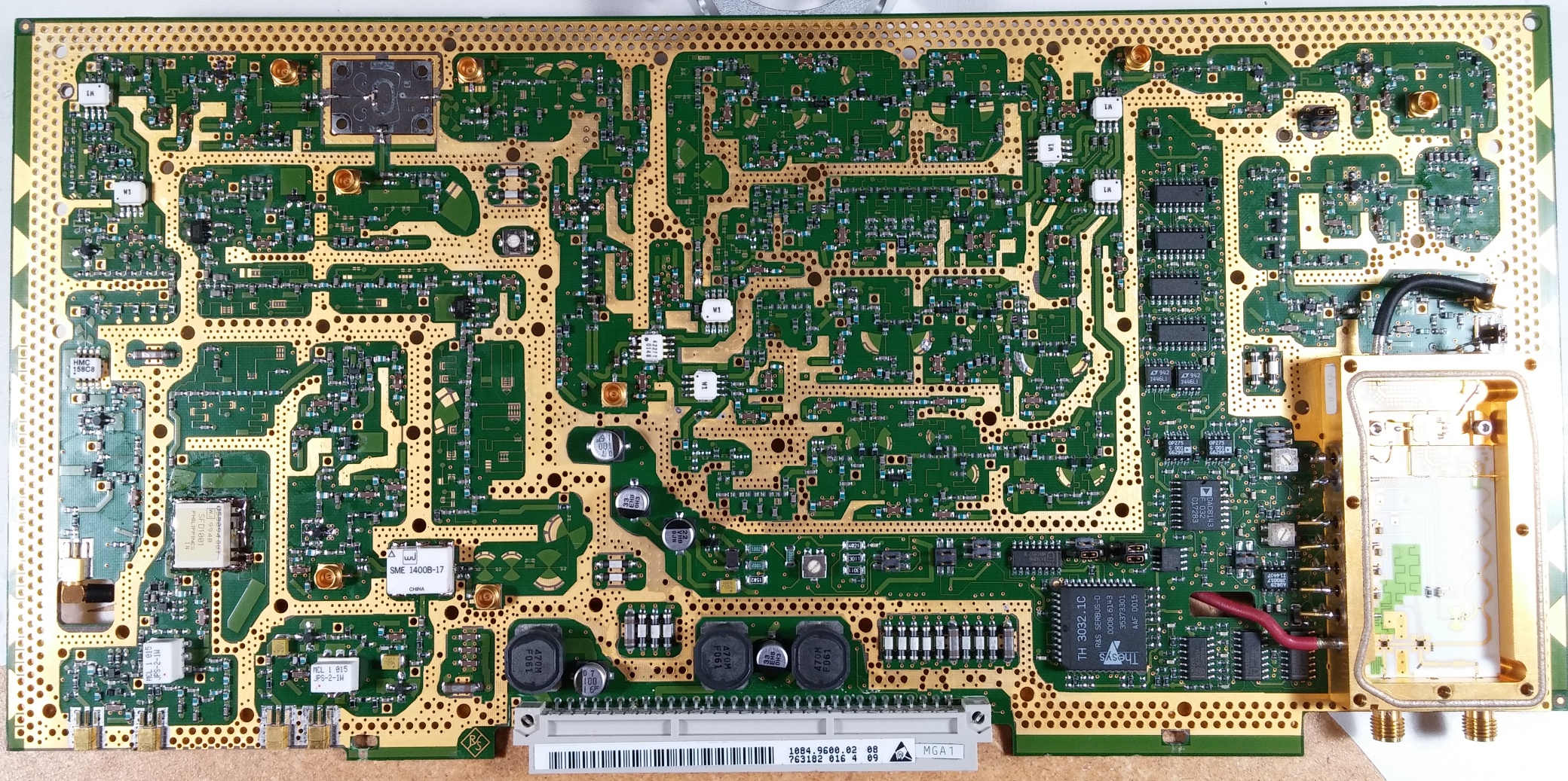
So from that last post proclaiming it fixed, I removed the card, removed the mod wires, replaced N3 with the same chip as N4, cleaned up a couple of odd looking joints from previous mod wire removals, and then sprayed down the flux residue with my fancy alcohol sprayer (airbrush).  Did a pretty reasonable job cleaning it, though I never had the guts to clean the hybrid power module with alcohol and was sure to wait after soldering (warm ground plane + fast evaporating alcohol in an airstream seems like a recipe for thermal fractures...).  And I was left with this nice clean board:


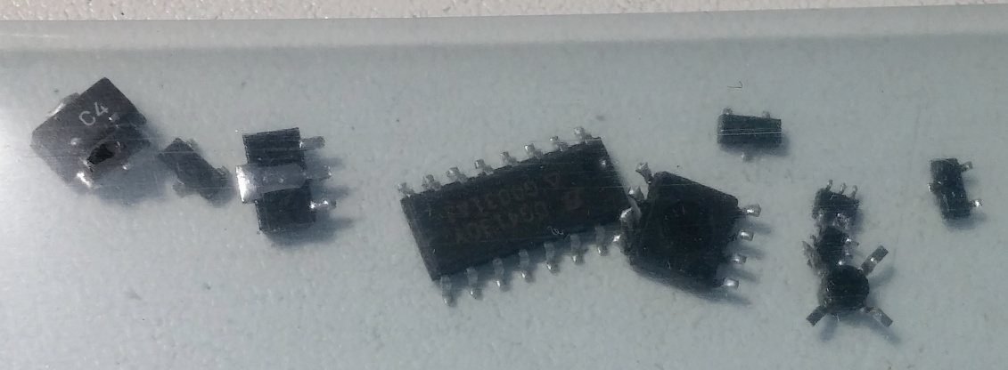
Over the last month and a half, I replaced all these parts.... though in retrospect and after seeing the fixed failure... several of these are probably fully functional  :-[


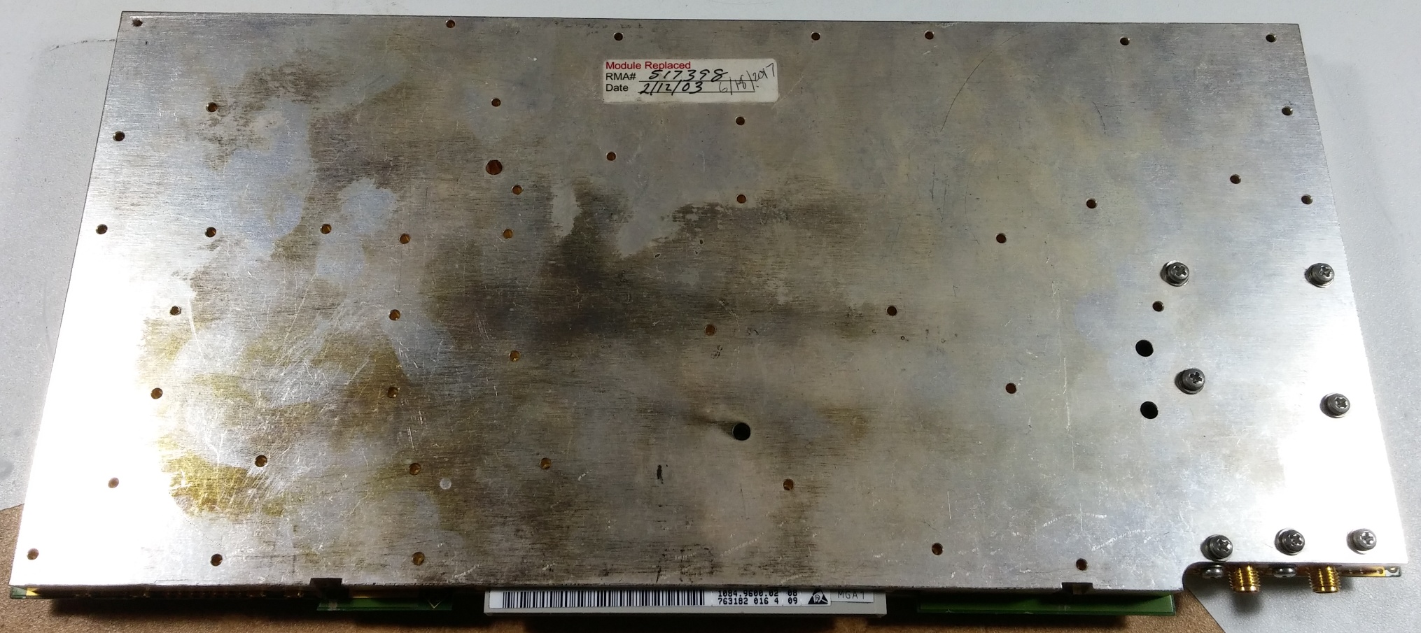
I put it back in and ran some tests for the sake of interest, then pulled it one last time to put it all back together.  I found that the silver tarnish came off the shielding very easily with a little rubbing alcohol, so I went around the edges and the RF gasket to try to make sure the seal was good, then I clapped on the two shielding boards and went to town on something like 40 torx screws.


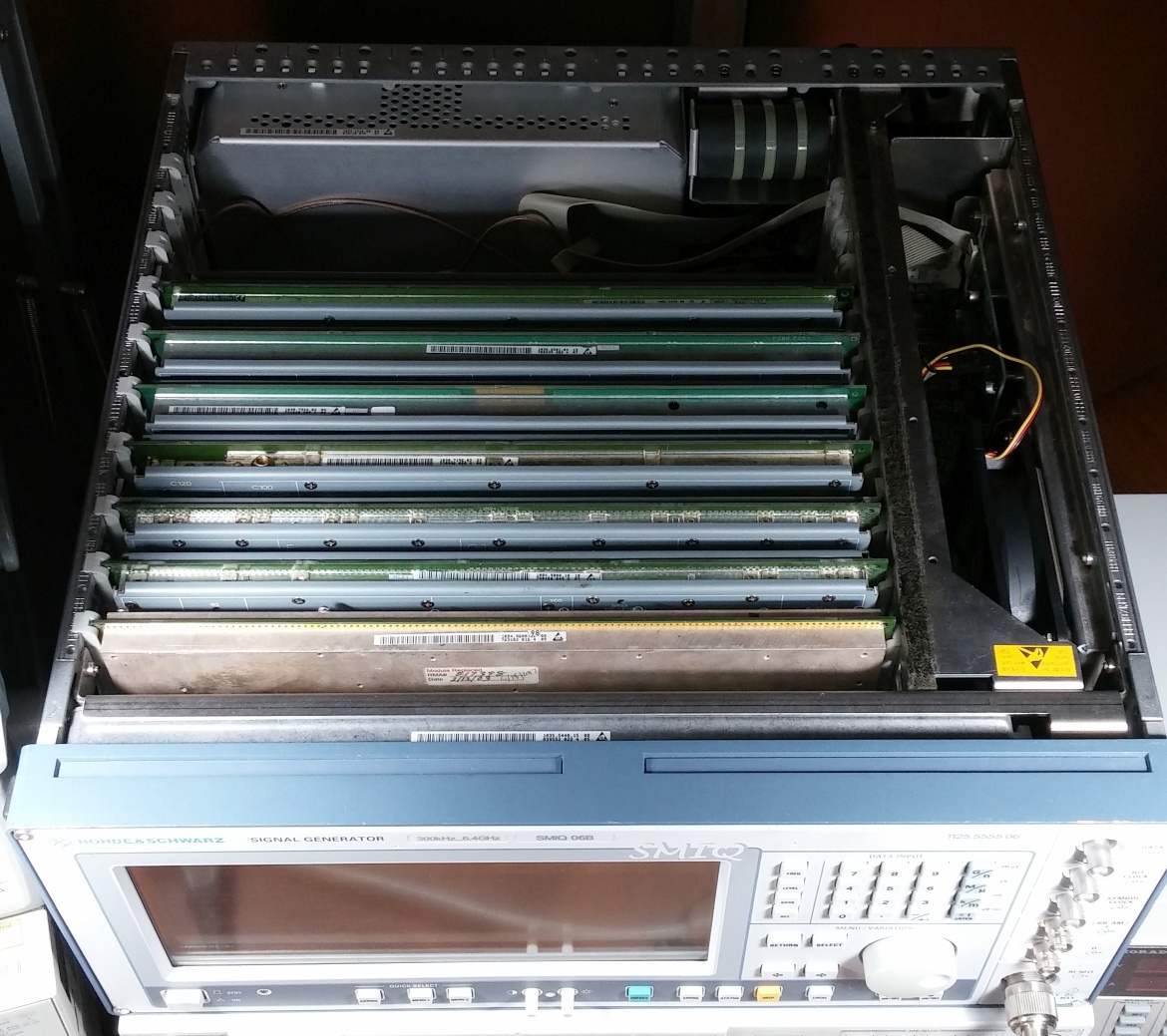
Then back in the box with the others, making sure the SMAs were nicely tightened:


Then after some testing, I slapped on the top and bottom housings and put on the back pieces... for a nice looking piece of functional test equipment.


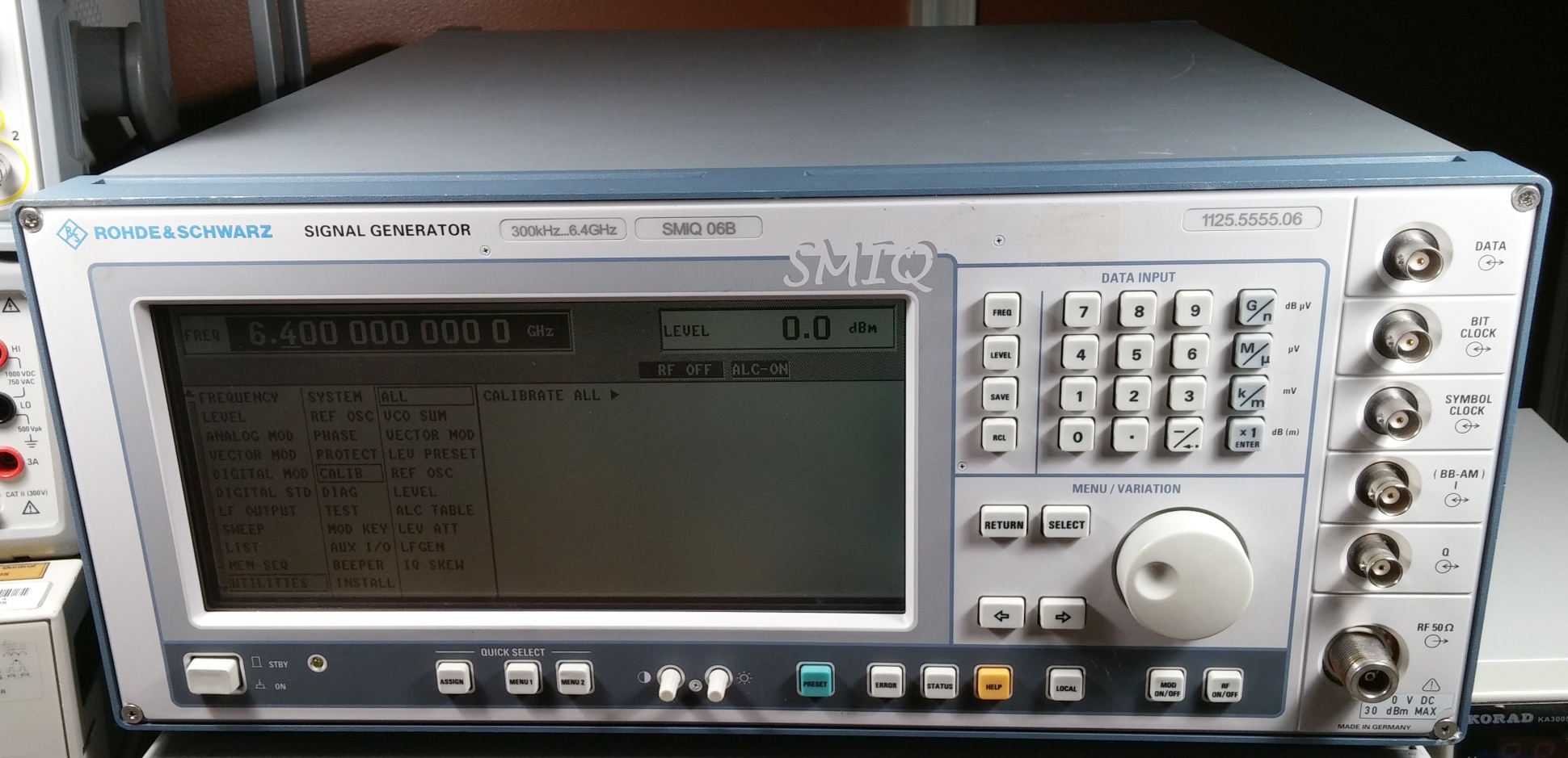
When it was fully together, I left it and the RF power meter on for a bit, ran the full self calibration of the SMIQ and zeroed my sensor and checked output linearity... it got a bit better!  At the bottom end, it's a bit under, I saw as far off as -0.23dBm when the output was set to 0dBm, but for most of the range it's off by only a few hundredths of a dBm, and right at the top it was +0.03dBm.  Quite pleased, especially given that the sensor's last cal was probably in the late 90s.

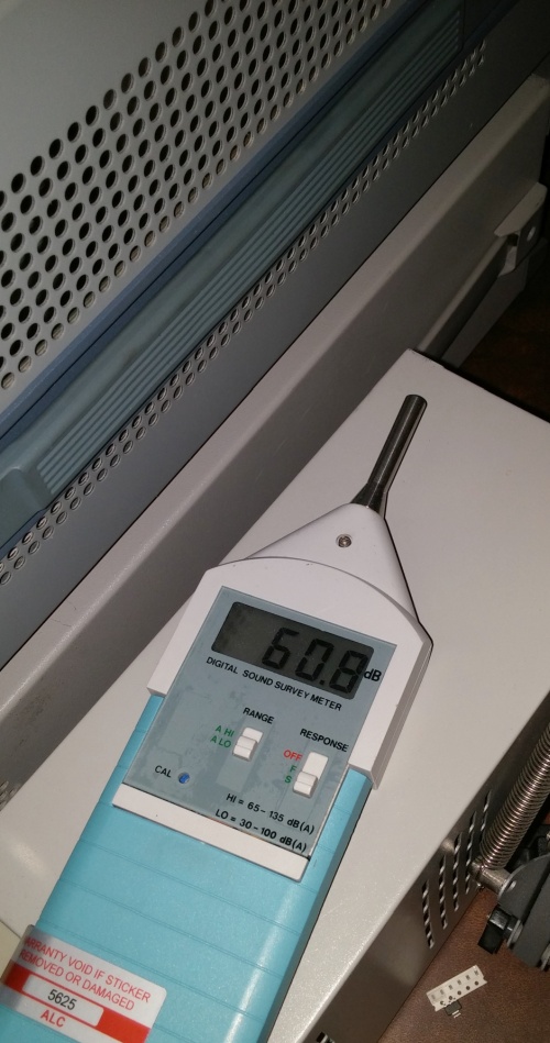
Also took a measurement of the sound level, at about the same positioning as before, and it's somewhere around 4.5dB down!  It's honestly higher than I expected from the reading, since it sounds much quieter to me, but getting the chassis on did get the noise up a bit.  Now instead of being pretty much the noisiest thing on the bench, it's under the stock fan for my DS4024 and my power supply takes the loud-operation crown once again.


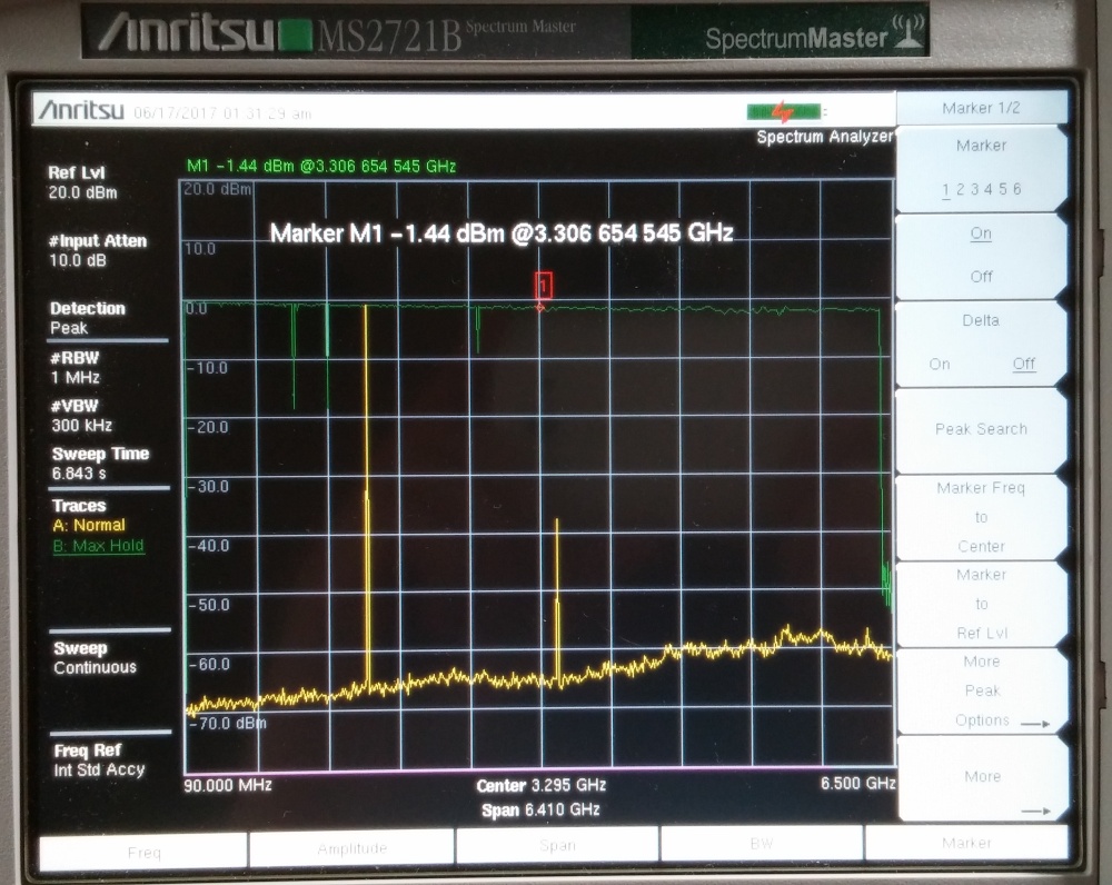
I took a nice long peak hold run of a frequency sweep output to get a general idea of linearity of the output (and I actually think the dropoff shown is more in the spectrum analyzer, since the cable should be fairly good and the power meter reads a lot less than this).  Regardless, it looks much better.


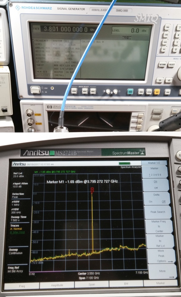
And while I'll go into the EMI readings later, even though the frequencies are slightly different, this gives you an idea of the noise reduction you get on the output with nice shielding.  With the shield @3.8GHz:


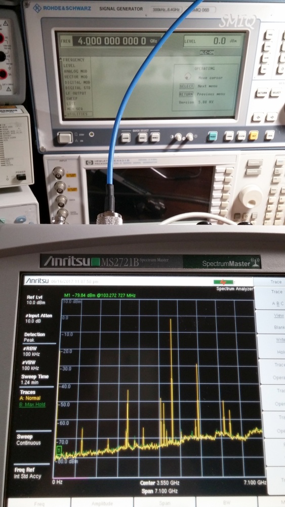
Without the shield at 4GHz (same frequency band, didn't remember to actually match the frequency or the RBW... but the trend is clear)


And to aggregate, I sent along the test point readings and are in the spreadsheet in the last post - these are accessible through the menu without opening the unit at all and without external gear.  And here's the measurements I noted down on the bias lines for the RF amps and some other things - always 2 inductors away from the signal path.  My board reports as Var. 2, Rev. 2 in the software, and it is somewhat different from the schematics (most of the "not populated" amps in the schematic are present.  I didn't note frequencies for most of them and I know frequencies changed somewhat (and a few intentionally are driven differently with frequency) so use these as guidelines, not necessarily correct values for your situation.

MGA86523 amps:
N14 - 3.125V
N25 - 3.133V
N35 - 2.784V
N36 - 3.959V
N37 - 2.905V

Other types
N38 - 4.913V, somewhat noisy
N39 - 4.906V, somewhat noisy
V20 - 4.457V, somewhat noisy
N15 - 4.537V
N17 - 4.513V, "chunky" noise (similar amplitude, but slower changing)
N4 - 6.612V-6.601V, THIS MEASUREMENT WAS TAKEN WITH THE FAULTY AMP
N3 - 4.72V-4.69V, gradual drop as it warms up THIS AMP WAS ALSO REPLACED AS A PRECAUTION
V87 - 4.423V, varies with level adjustment

V91 bias: 4.71V
V92 gate: -1.35V
V92 bias: 7.133V
V94 bias: 7.05V
V95 bias: 7.05V

V191 gate: -5.039V
Power module VDD: 7.2V

It's also worth noting that the faulty N3 did not measure any differently from N4 when removed from the board using a multimeter's diode check function even though it was clearly the fault.  A number of diodes and things read really strange testing this way in circuit, even when the circuit seemed very simple, only to be fine and consistent when removed.

Some RF noise investigations to follow to round out my work in the unit.
« Last Edit: June 20, 2017, 04:06:15 am by DaJMasta »
 
The following users thanked this post: KE5FX, smgvbest

Offline DaJMastaTopic starter

  • Super Contributor
  • ***
  • Posts: 2297
  • Country: us
    • medpants.com
Re: Rohde & Schwarz SMIQ06B repair log - 6GHz board ALC error - FIXED
« Reply #53 on: June 23, 2017, 05:43:53 am »
And as promised, a final post with some extra info - basically just curiosities that I could indulge when it was partly disassembled.

The first big one was: how much does the shielding actually do?  Well, predictably, the answer was a lot.  First in terms of purely radiated energy, I took my handy E field probe and stuck it over the board, about centered.


And with the top off I took some measurements with the spectrum analyzer:


Full set of measurements here:
http://www.medpants.com/pics/smiq06/100Mradio.jpg
http://www.medpants.com/pics/smiq06/1Gradio.jpg
http://www.medpants.com/pics/smiq06/2Gradio.jpg
http://www.medpants.com/pics/smiq06/3Gradio.jpg
http://www.medpants.com/pics/smiq06/3.8Gradio.jpg
http://www.medpants.com/pics/smiq06/4.6Gradio.jpg
http://www.medpants.com/pics/smiq06/5.4Gradio.jpg
http://www.medpants.com/pics/smiq06/6.2Gradio.jpg
http://www.medpants.com/pics/smiq06/smiqradio.jpg

And then in the same measurement configuration with the shield on, I took a similar set of measurements... but I don't need to post all of them.  I left the max trace (green) going during the whole test without resetting, and the shielding performed so well, the max trace basically looked like every measurement stage.  The one peak is the house wifi.


So for radiated RF, the system certainly works.  How does that look on the output though?
Well because I knew we'd at least see some mixing products on the uncovered board, I captured the screen alone of the analyzer when manually sweeping the range.  The first few are 100MHz apart while the rest are 200MHz, and the marker lies where the frequency range crosses over to use the 6GHz extension board, which was uncovered for the test.  This is a direct capture of what's coming out of the front N connector when the shielding is NOT in place.


Really fascinating for me to watch, not only can you see the filtering being switched on for different bands, but you can see the way the LO frequencies change and reset for higher bands.  And all this is being radiated from where it should be filtered out, picked up in the signal path, and then amplified and fed out through the front panel.

Of course, the output looks a lot better when you put the shielding back on.  3.301GHz is included because anything above 3.3GHz is done on the 6GHz extension board:


http://www.medpants.com/pics/smiq06/100Mcovered.jpg
http://www.medpants.com/pics/smiq06/1Gcovered.jpg
http://www.medpants.com/pics/smiq06/2Gcovered.jpg
http://www.medpants.com/pics/smiq06/3Gcovered.jpg
http://www.medpants.com/pics/smiq06/3.301Gcovered.jpg
http://www.medpants.com/pics/smiq06/3.8Gcovered.jpg
http://www.medpants.com/pics/smiq06/4.6Gcovered.jpg
http://www.medpants.com/pics/smiq06/5.4Gcovered.jpg
http://www.medpants.com/pics/smiq06/6.2Gcovered.jpg
http://www.medpants.com/pics/smiq06/6.4Gcovered.jpg

Then as a final test, I just zoomed in on a nice central signal to see what could be seen.  Neither the analyzer nor the generator were on a reference clock and this SMIQ does not have the high stability timebase, so it's a bit under what it should, but the signal coming out seems pretty clean.


It's been interesting for me to do and I'm quite pleased with the result.  Hopefully it's interesting or useful to some of you too!
 

Offline DaJMastaTopic starter

  • Super Contributor
  • ***
  • Posts: 2297
  • Country: us
    • medpants.com
Re: Rohde & Schwarz SMIQ06B repair log - 6GHz board ALC error - FIXED
« Reply #54 on: March 11, 2018, 10:28:32 pm »
So as mentioned in a repair thread for a similar failure ( https://www.eevblog.com/forum/repair/rohde-schwarz-smiq06b-repair-6ghz-board-level-preset-error/ ), after several hours of use beyond the period I had tested, the fix detailed eventually started showing ALC errors again.  As is common with my projects, it sort of got shuffled into the pile and it was some months until I picked it up again.  However, a couple weeks ago it resurfaced, and I've got another fix that I can detail - which has been working fine for about half a dozen hours of uptime so far.

So to start, I hooked up the power sensor and took a look at the test points, and unsurprisingly, it read low then the ALC error showed, but somewhat surprisingly, on most frequencies at 0dBm output level, after the instrument had warmed up, it could go through most frequencies without actually triggering the ALC error.  Taking a look at test point values, a couple points were low, and when the ALC error appeared TP2413 was slammed against the top rail (not a rail to rail opamp off a 15V supply), but that it settled to a more normal range when working properly.


From that, and knowing that the SHF-0186 track record of being problematic in these instruments, I decided to swap V94 and V95, the amps right before the main power amp, for fresh ones.


The result was a stable, at the correct level output - great!  But on trying to relearn the ALC table, it failed partway through with an Error 180 "Range oot" message.  Not knowing exactly what oot was (out of tolerance?), I took a look at the test points again to see what had changed - and two values were considerably over the previous working values... so after examining the schematic again, I figured it was probably that it was trying to attenuate the output level (though the PIN diodes or through the amp biasing) too far in trying to level out the output to a point that the instrument threw an error.

So I needed less amplification in the signal path - specifically, right before the measurement points 2409 and 2410.  The biasing mechanism for the SHF-0186 amps is a variable transistor based thing with a bunch of elements that biased both sides of the amp with varying voltages/currents, so I opted for changing the fixed bias of the MGA82563 amps, first N25 and then N35 (before and after the split filter bank).  I did this by swapping the 23.4 ohm resistors at R39 and R320 (N35) as well as R934 and R935 (N25) for 33 ohm resistors (0805s since I didn't have any 0603s of the right value).  That additional resistance reduces the current going into the amp and the output level of each - after both, the full calibration would complete and the output is level and error free again!


Also, since the previous "fix", I've gotten a HDMI inspection microscope as well as a capture card, so I took the opportunity to take a couple quick pictures of some RF bits on the board.

First, the main mixer


Then the detector elements in the power module


And finally, the RF switch towards the bottom of the power module


I also found an inexpensive SM-B5 option card (FM modulator) that I installed quite easily.  The instructions were fairly clear and the included RF cables had their connections indicated on the heat shrink.  The only difference is that after installation, the procedure calls for holding the reset button when powering on to recognize new options... after a couple minutes of looking, I couldn't find a reset button and just powered it up.  The initialization screen was up for 2-3x as long, but the card was immediately active and available to use.  Easy!  Hope this thing stays fixed this time!
 

Offline charlyd

  • Frequent Contributor
  • **
  • Posts: 525
  • Country: nl
Re: Rohde & Schwarz SMIQ06B repair log - 6GHz board ALC error - FIXED
« Reply #55 on: February 25, 2022, 05:10:38 pm »
hi i think i post it here also :  any tips/suggestions on these components location N4 = code 301 and location N3 = code 802 / 8026 see link below i posted

the top pictures found in the topic here, -> the schematic version
the bottom zoomed pictures from my board ( unit was sealed when opend )

from my opinion the components are upgrades for the N3 and N4 and added by R&S  ( my e6GHz Var2 Rev3 )

https://www.eevblog.com/forum/repair/rohde-schwarz-smiq06b-repair-6ghz-board-level-preset-error/msg4029241/#msg4029241
 

Offline charlyd

  • Frequent Contributor
  • **
  • Posts: 525
  • Country: nl
Re: Rohde & Schwarz SMIQ06B repair log - 6GHz board ALC error - FIXED
« Reply #56 on: June 21, 2022, 01:55:52 pm »
i guess the N4 = mmg3012nt1   (coded 301 ? )

ok and now still N3 ( coded 8026 )
 

Offline charlyd

  • Frequent Contributor
  • **
  • Posts: 525
  • Country: nl
Re: Rohde & Schwarz SMIQ06B repair log - 6GHz board ALC error - FIXED
« Reply #57 on: September 03, 2023, 08:43:07 am »
Hell i replaced N3 already (with a  MMG3012NT1) not yet N4. part of my errors(LEV PRESET) are gone now. but not yet the error:  CW: ALC_ON voltage oot so producent the ALC Table Failure.... is this maybe related to the fact that i also need to swap out N4 (with a MMG3012NT1 of course) to solve this last error.

or did i miss something else like these posts tells me:
--------------
Hello.
Calibration is failed for this reason:
IQCON no convergence
Error: CW: ALC_ON voltage oot;
Check IQ converter module.
Regards, Sebastijan.
‐-----------------
https://www.eevblog.com/forum/repair/smiq03b-errors-after-battery-change/msg3528756/#msg3528756
« Last Edit: September 03, 2023, 12:20:47 pm by charlyd »


Share me

Digg  Facebook  SlashDot  Delicious  Technorati  Twitter  Google  Yahoo
Smf