The Metratop 51 is one of three Models build into this kind of case.
Other models are the Metratop 52 with a second channel for voltage measurements and the Metratop 53 with a calibration generator build in. But these seem to be very rare, close to non existing on the market.
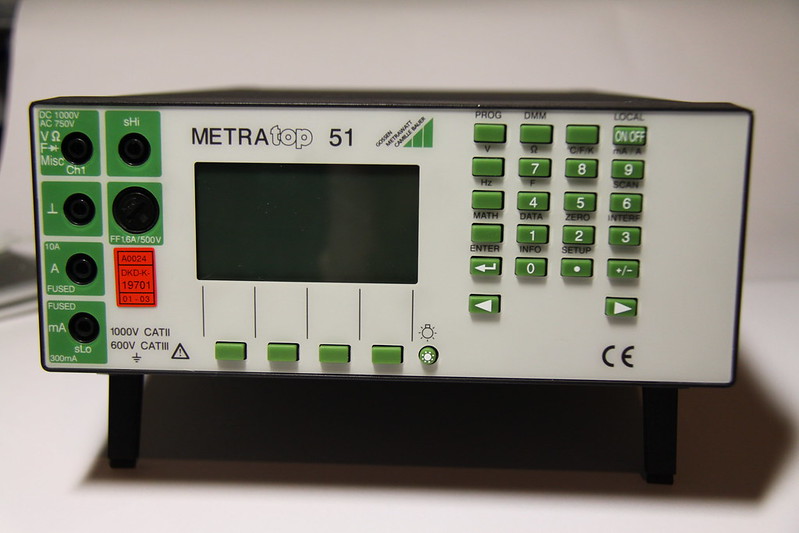 The Device unpowered. Look at this german baroque beauty of the early 2000s.
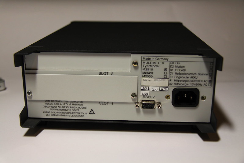 The backside with unfilled slots for options.
It features a 5 3/4 Digit Display (updated 2/sec at full resolution), a RS232 Port, 2 and 4-wire Ohms, temperature, frequency and capacity.
Build in are a real-time clock, one can use it as counter, stop-watch and store measuring in the internal memory.
Unfortunately, the stored measurings are only accessible via Computer.
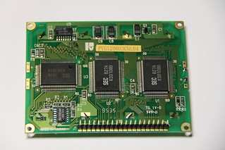
The Display is a graphical one with 128*64 pixel resolution (containing a KS0108 Chipset) and originally yellow/green illuminated. The light can be switched on and off separately.
The instrument can be upgraded with a batterypack (NI/CD or NIM/H) which is charged when the meter is plugged into mains.
Also available ist a scanner option, a modem and/or fax connection. It is also possible to retrofit a IEEE-488 Controller.
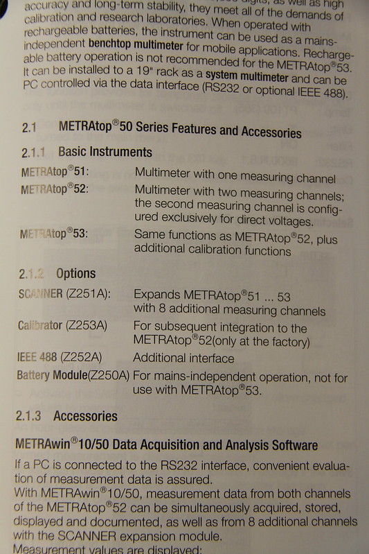 Options one could buy.
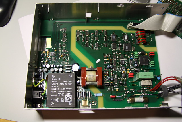
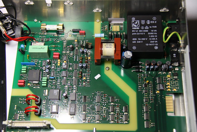
Inside the instrument are 2 multi-layer circuit boards:
- the mainboard containing the powersupply and mainly analog (measuring) circuits for the frontend
- the display/keypad board with the main processor
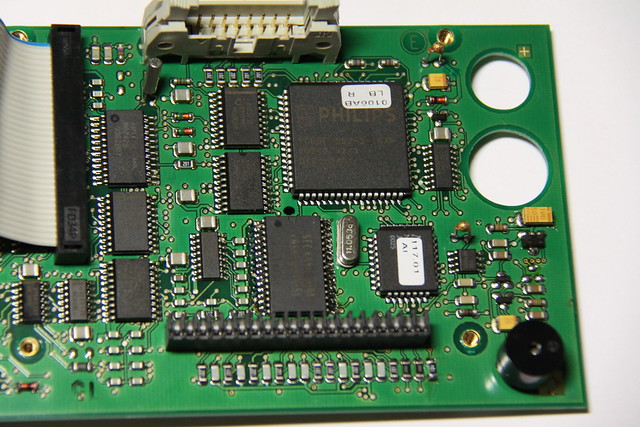
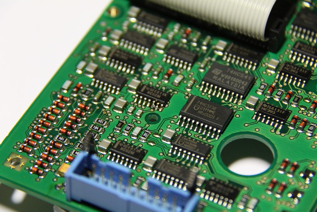
 Mainboard, Processor part of display board, more display board logic, display board with pushbutton traces.
The power supply is an interesting build.
The mains transformer (capable 120 and 240 volts) has 2 separate windings on the secondary (6v) wich are connected in parallel. A bridge rectifier and a cap do their job perfectly to make a stable 9v.
Afterwards is some kind of battery charging circuit and a switch-mode DC to DC converter.
From separate taps of the transformer are the voltages for the logic and the analog fed to the circuits.
The device is always on hence the power cord is plugged in; it only does a soft-power off.
Weird enough, the realtime clock (M6242B) is not battery buffered so every time you pull the plug the clock needs to be set.
The digital controls on the display board are done via a 80C552 8-bit 8051-like controller. This controller drives the display, scans the keyboard, does the RS232 and communicates with the analog frontend. It runs at 11.05MHz.
The firmware is stored in a flash (!) memory 29F010, a 128k static RAM is used for data. As for the clock, there is no battery buffer for the RAM. (More than weird again, because these two chips are powered separately from the supply.)
Three temperature sensors are around the processor, one is used as internal reference for the external probe. I can’t really imagine what for the others are.
The analog (measuring) and digital circuits are completely separated on the board, commands from the front panel controller to the measurement controller are transfered via a two induction loops near the front of the instrument.
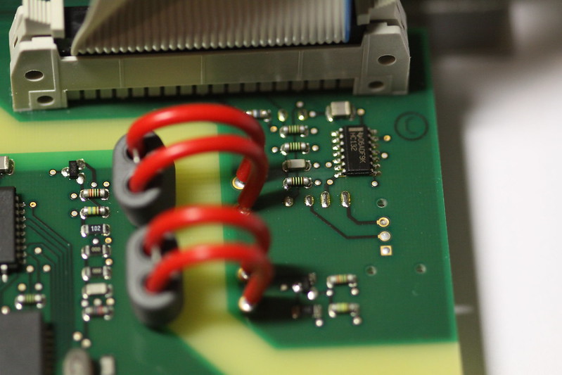 induction loop for coupling the two functional parts.
The analog (measuring) part of the board is controlled by a 8032 controller running at 11.05MHz. Software is stored again in a flash 29F010, 8k static RAM is attached.
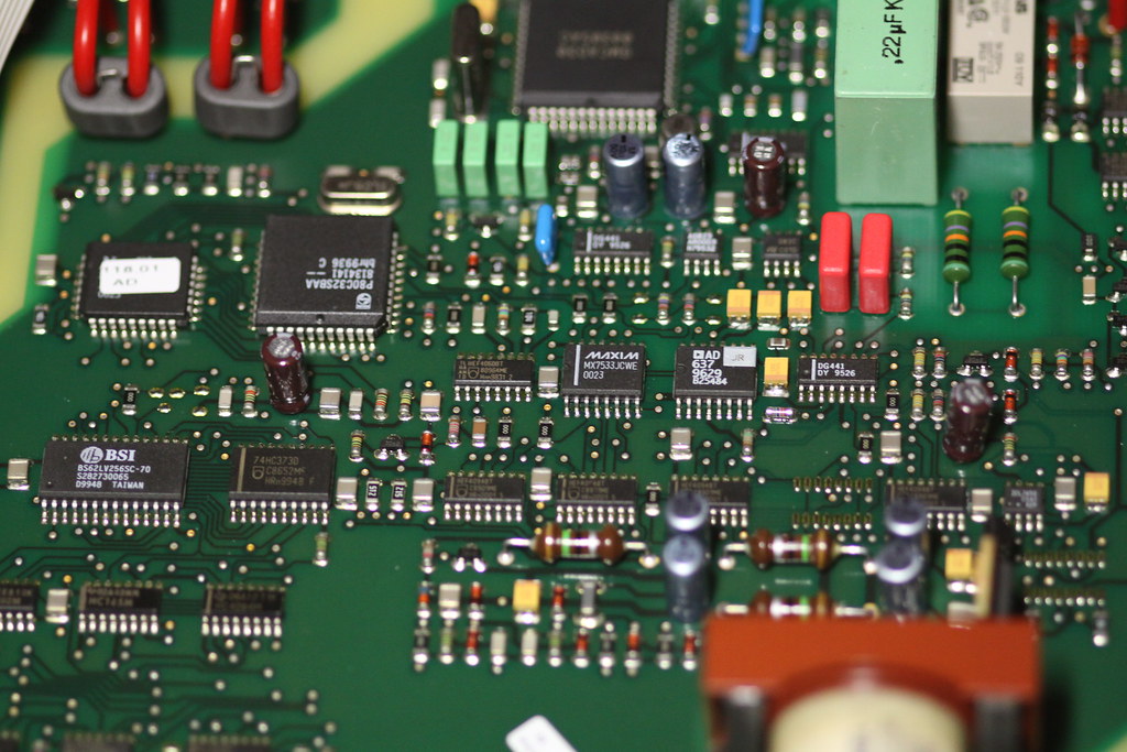 controller on the analog part of the mainboard. In the top/middle of the picture is a GMC custom chip. All other parts used are pretty standard.
The whole instrument is bodged all over. Several desolderings have been done, new components put in place, there is one bodge-wire on the display board feeding some components with +5V.
Overall, the whole instrument ist a very nice an accurate one. The size and weight is comparable to a Keithley 2000 and tons of features for a former, very reasonable low price of about 500,- Euros makes it a bargain nowadays.

 more pictures. The underside does not contain any parts.
The Instrument I own has had a defect and was sold as defective.
Some investigations, starting with the power supply and display-board gave at first no clue what could be wrong with the device.
I could power it on, push buttons and switch the modes, but the display didn’t show anything except the backlight.
Digging further on I got aware of the fact, that the power-button ist not only scanned by the processor but also works as a push-button for the power supply.
When pressing the power button, the logic for the power supply puts 5V to the display/processor board, the processor boots up and holds the logic for the power supply up.
So, my conclusion was, that the processor did work properly.
A short support call to Gossen gave me the answer I expected: the display should be defective. A repair at Gossen would cost 250,- €, the display only would be around 130,- €.
After some digging in google I found various compatible displays from 13,- to 19,- € to purchase. I got 3 variants and they all worked well with the instrument.
Except the dimension (thickness) of the displays differ from the original, I found the grey/blue display with the white backlight fits the best and does not bulge the foil in the front of the display.
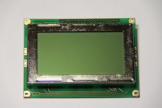
 Defective display. Does not generate the -9V contrast voltage any more.
Some fiddling with the contrast voltage lead to a now very fine working instrument.

 Working fine and spot-on compared to my Fluke 289 and Keithley 2000
Feel free to browse through my Flickr Gallery (
http://www.flickr.com/photos/uferst/sets/72157642914867723/) to see more photos and the specs of the instrument.
Sorry for my bad english, I'm not a native speaker and may use wrong words or grammar during this text. Please feel free to comment.


