OK folks watch this YouTube video first to appreciate the teardown and the device. Sorry for the poor quality, the video is not mine.
I was looking for a barcode scanner and came across this video. I was impressed to say at least. I went on eBay and right away got incredibly lucky and found one for just $40 from a local seller. The unit came fully working and with a charged battery

, though fairly worn cosmetically, which could be expected from use in a warehouse, as you could see in the video

It is a Windows Mobile rugged portable computer with a barcode scan application and a so called Long Range scanner. It indeed is able to scan a 3'x1' size barcodes from 2m distance which I think pretty impressive, though I did not research what long range scanners are capable of in general. It also have built-in WiFi which I could not get on my wireless network but I think it may be because of my router and because the old version of the mobile OS. But my main interest was to see how the hell they build it to survive that sort of abuse. And I wanted a bar code scanner anyway so that was a cheap solution. Hell, only $46 with shipping
.I only need to find or make a charger for it


There are several modifications of it with different OS versions, features, as well as key pad size. I got one with complete alphanumeric set and there are ones with just numeric and navigation keys which makes the device shorter in size. Mine also is with a pistol grip type of back cover, though I believe I could buy a normal handheld back cover and replace it. For barcode application it is better though to have a pistol grip handle because of the convenience to point to the target and the heavy device balances nicely in the hand and it is much less tiring for prolonged use.

If you watched the video, here is the famous "Exit window" , the laser beam clear window. I was curious if it is also IR transparent and checked with my FLIR E4 thermal imager, but it was not.

The battery removal is two-step. First you push two metal clips on the sides, that unlocks the battery and it pops out a little but still held by a metal strip with a notch. To fully remove the battery you push the green end of the notch strip and the battery slides out right into your hand. I think it is a brilliant design solution - be it just two side clips, the battery would often just fall down on the floor, or ejected out if the device was dropped and the locking clips got lose. With this design the second clip will catch and keep the battery inside the handle.

The battery has a number of hold plated connectors at the bottom for attachments and the charger or holster. The connectors seem to go right through to the other side of the battery where they mate with the device connectors when battery is inserted.
I was at first puzzled how to open the device. I found two screws on the outside of the pistol grip by the exit window and two screws inside that can be accessed after the battery removed, but still could not detach the pistol grip. It was dead clinched to the device! I had to watch a few videos before I spotted a clue. Then the device came apart. The secret sauce was in the device enclosure locking design as we can see in a sec, so to detach the pistol grip cover you apply a bit of force and slide it towards the exit window and away from the battery end (after removing the 4 aforementioned screws).

So here is the close up of the secret sauce. Note the teeth and groves on the back cover (right side) and the corresponding locking teeth on the top cover (left side). You put the covers together with a bit of offset so the top cover teeth go into the space between the bottom cover teeth, then slide the bottom cover towards the bottom of the picture so the top cover teeth slide into the grooves. You then tighten the two screws from inside the battery compartment and the force will further pull the covers together and that creates a dead grip! Brilliant !!
This is why it is so difficult to crash this puppy. A robust impact resistance plastic material plus the locking teeth design.

But I still wanted to see how the electronics was mounted inside the device so it is capable of taking so much shock.

Next goes the keypad which has the same locking teeth design. To detach, remove two screws located below the screen and slide the keypad away from the screen then up. It takes a bit of force because of traction between the teeth. Removing the keypad opens access to a compartment with a full size SD card slot. My understanding the purpose of the SD slot is for the OS updates and to load optional features.

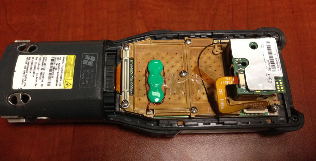
We can now take a look at the open back of the device. Just a backup battery there and the bar code scanner module, mounted on a (presumably) some sort of aluminum alloy plate which is also the PCB top cover with little walls between PCB functional circuits. Note a clip with ribs and two screws firmly holding the keypad flat cable connector. No way the keypad SMT connector can ever get loose or the clip get bent. Nice attention to details.