Author Topic: Gordak 952-v hot air solder station - high failure rate - what cause?  (Read 47550 times)

0 Members and 1 Guest are viewing this topic.

Offline asbokidTopic starter

  • Regular Contributor
  • *
  • Posts: 57
  • Country: gb
Hello,

We have suffered several failures of the Gordak 952-V solder station.   The 952-V is one of the newer VFD models. It costs around US$150 delivered. So not the cheapest. [1]

The symptoms are dead screen and dead control buttons, cold blower and cold iron.


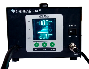
Gordak 952-V (when working!)

The seller says return the faulty stations for repair/replacement. But this is impractical. Return shipping to China costs as much as a new station.

Since the problem is common - it would be better to identify and fix it, and document the solution for others.

The Gordak 952-V is driven by an Atmel ATmega8L-8PU 8-bit microcontroller. The MCU is clocked externally at 8MHz. The MCU has an 8 bit AVR RISC core, 8kB of onboard flash, 512 byte EEPROM and 1kB of internal SRAM, and three digital IO ports.  [2]

The VFD screen on the Gordak is driven by a Princeton PT6312 VFD controller.  The PT6312 can be seen on the reverse of the board below. [3]

The MCU drives the PT6312 via a 3 wire serial interface using its GPIO lines.

The Gordak's control board also has a couple of OP07DP operational amplifiers, and a TL431 adjustable voltage regulator. [4]


So it is not clear where the fault lies.  The Gordak does have a separate power supply board. This was briefly tested and its outputs appear to be clean and in spec.

There are vendors on Taobao selling pre-programmed replacement MCUs for the Gordak 952-V. This suggests that their failure is common. Yet the ATmega8 is pretty resilient, so the underlying fault with the Gordaks is probably something else.

There are schematics for the earlier Gordak 952 [5] and for the Gordak 952A [6] but neither are very relevant to the MCU-based Gordak 952-V.   The 952-V User Manual (Chinese and English) is here for anyone who has lost it. [7]

Any suggestions or pointers would be gratefully received  :)

cheers,
asbokid

[1] http://www.totobay.com/gordak-952v-intelligent-compositive-soldering-station220v_p29555.html
[2] http://www.atmel.com/images/doc2486.pdf
[3] http://www.princeton.com.tw/downloadprocess/downloadfile.asp?mydownload=PT6312.pdf
[4] http://www.ti.com/lit/ds/symlink/tl431.pdf
[5] http://archive.espec.ws/files/gordak.rar
[6] http://img339.imageshack.us/img339/2428/hotairschematicchamobil.pdf
[7] http://docs.google.com/folder/d/0B6wW18mYskvBQWlZN19B...
« Last Edit: October 07, 2012, 11:00:07 pm by asbokid »
 

Offline amspire

  • Super Contributor
  • ***
  • Posts: 3802
  • Country: au
When you are getting a blank display and nothing seems to work at all, the first thing you do is to check the 5V on the micro, the +/- supplies on the opamp and supplies to the display chip (if you have data). If you measure the voltage across the front panel switches when they are not depresses, is there any voltage? What is the voltage on the micro Reset pin?

The schematics of soldering irons are fairly simple - it is not that huge a job working out the schematic by following the traces on the PCB's. It is a few hours work, but if you post a rough a circuit, we can probably help you. Things like the display are not that important. The circuit connected to the main micro is important. The power supply circuit is also needed.
 

Offline asbokidTopic starter

  • Regular Contributor
  • *
  • Posts: 57
  • Country: gb
Hi Amspire,

Thank you for your interest  :)

  • VCC and AVCC on the ATmega8L are both +5.00v and GNDs are good.
  • VDD on the PT6312 (VFD controller) are +5.00v and good GNDs
  • RST on the ATmega8L is +3.80v. And probing RST with a multimeter seems to cause the MCU to reset, detectable from the pump briefly pausing.
  • V+/V- on the two OP07s op-amps both read +10.00v
  • The three front panel push button switches have +5.00v when not depressed

So the power supplies seem okay, and maybe the ATmega8L isn't fried after all, or at least not all of it  :P

What could I check now?


« Last Edit: July 23, 2012, 05:13:00 am by asbokid »
 

Online Psi

  • Super Contributor
  • ***
  • Posts: 9930
  • Country: nz
Do you have any working units?  If so you could leave one on for a while, then unplug it, take the top off and check all the components for any hot spots.
It might yield clues if you find something that's quite hot.

And if you're willing to dismantle a working unit it makes fault finding easier.
You can compare in-circuit measurements between a good and dead unit, looking for differences.
« Last Edit: July 23, 2012, 05:45:44 am by Psi »
Greek letter 'Psi' (not Pounds per Square Inch)
 

Offline amspire

  • Super Contributor
  • ***
  • Posts: 3802
  • Country: au
RST on the ATmega8L is +3.80v. And probing RST with a multimeter seems to cause the MCU to reset, detectable from the pump briefly pausing.
When it is working, does the pump run 100% of the time, or is it turned ON and Off by the micro?

I would start looking at the connections to the reset pin and work out why it is 3.8V rather then 5V. It could be OK, or it could indicate it is being pulsed or is floating. If it is being pulsed, the micro can never run. Not sure why probing the reset pin should change the state of the Reset.

Trace the tracks, and draw the reset circuit.  I think it is worth 5 minutes.

Richard.
 

Offline David_AVD

  • Super Contributor
  • ***
  • Posts: 2806
  • Country: au
Just going by the photos, pin 1 of the Atmel micro (RESET) seems to be floating???
 

Offline amspire

  • Super Contributor
  • ***
  • Posts: 3802
  • Country: au
Just going by the photos, pin 1 of the Atmel micro (RESET) seems to be floating???
That is interesting. They could have used the RSTDISBL bit in the micro fuses to disable the external reset pin, but if they forgot to program the fuses properly with a batch of chips, it would default to being a floating Reset pin. The fuse table is separate from the compiled micro code, so it would be easy for someone to program the micro EPROM correctly, and not the fuses.

That would mean that the soldering station would run or not depending on what value pin 1 was floating at.

I would add a 10K to 1M resistor from pin1 to +5V and see if that fixes the problem. The 5V supply rail track pass within about 0.2mm to pin1, but it looks like there is no connection.

Richard.
« Last Edit: July 23, 2012, 07:21:58 am by amspire »
 

Offline MBY

  • Regular Contributor
  • *
  • Posts: 184
  • Country: se
That's strange! The only reason for using the RSTDSBL fuse is to use the pin for IO. But clearly the pin is not used at all, hence no need for the RSTDSBL. So, a 10-100 k to the supply and perhaps a 10-100nF to GND may be good to add.

Maybe this is some sort of idiotic "protection", like sanding chips. With RSTDSBL sat, it is harder to read/write the flash from a programmer. But this is not the right way to do it. Lock bits are there for a reason.

But is does not seems like this is the only problem.
 

Offline asbokidTopic starter

  • Regular Contributor
  • *
  • Posts: 57
  • Country: gb
Thank you for all the advice and suggestions, guys. Much appreciated  :)

Next plan is to scope the ATmega8 pins for signs of life.  The MCU pinout is mostly understood now. 

The two op-amps take as input the two temperature sensors in the iron and in the hot air gun.  Those analog samples are amplified and fed to a couple of ADC lines on the MCU.   The MCU then uses its digital I/O lines to control the power supplies to the iron, the hotair pump and element.   On the PSU board there are three triacs, just as Kerry D. Wong found with a similar solder station [1].   Quite a simple board really, if only it worked!

I still reckon the MCU is fried, or just maybe the flash or eeprom has somehow gotten corrupted.  Hmm..  However, I just noticed some blackening in the very corners of the VFD screens. Not looking so good.  :'(


cheers, asbokid

[1] http://www.kerrywong.com/2011/12/07/x-tronic-4040-hot-air-reworksoldering-station-ii/
« Last Edit: July 24, 2012, 12:22:25 am by asbokid »
 

Offline amspire

  • Super Contributor
  • ***
  • Posts: 3802
  • Country: au
If they did forget to program the Atmega fuses, then you could read the whole code from the micro. That would be brilliant!

Put a socket in, and try out your own mods.
 

Offline David_AVD

  • Super Contributor
  • ***
  • Posts: 2806
  • Country: au
Re: Gordak 952-v hot air solder station - high failure rate - what cause?
« Reply #10 on: July 24, 2012, 12:02:17 am »
So you're not going to try fixing the floating reset pin issue?  A 10K resistor and 2 minutes work is all it will take.
 

Online Psi

  • Super Contributor
  • ***
  • Posts: 9930
  • Country: nz
Re: Gordak 952-v hot air solder station - high failure rate - what cause?
« Reply #11 on: July 24, 2012, 12:24:12 am »
Pretty sure the ATMEGA/TINY has a built-in 30-80k pull-up for the reset line.

Although recommended, a pull-up on reset shouldn't be needed to make it run.
Greek letter 'Psi' (not Pounds per Square Inch)
 

Offline David_AVD

  • Super Contributor
  • ***
  • Posts: 2806
  • Country: au
Re: Gordak 952-v hot air solder station - high failure rate - what cause?
« Reply #12 on: July 24, 2012, 12:37:42 am »
Pretty sure the ATMEGA/TINY has a built-in 30-80k pull-up for the reset line.

Although recommended, a pull-up on reset shouldn't be needed to make it run.

Fair enough.  I'm a PIC person so wasn't sure.

The 3.8V on the reset pin did sound odd though.
 

Offline asbokidTopic starter

  • Regular Contributor
  • *
  • Posts: 57
  • Country: gb
Re: Gordak 952-v hot air solder station - high failure rate - what cause?
« Reply #13 on: July 24, 2012, 12:40:34 am »
So you're not going to try fixing the floating reset pin issue?  A 10K resistor and 2 minutes work is all it will take.

I certainly will try that fix.  No time left tonight though :-(  You Ozzies and Kiwis are to be envied.  You get to stay up all night hacking away while us Pommies are forced to bed (not least for beauty sleep which by God we need!)

Viz sanding off chip markings  ::) This is a replacement MCU for that Gordak 952-V.   I wonder which MCU it is?!  ::)


cheers, a
 

Offline asbokidTopic starter

  • Regular Contributor
  • *
  • Posts: 57
  • Country: gb
Re: Gordak 952-v hot air solder station - high failure rate - what cause?
« Reply #14 on: July 24, 2012, 01:12:28 am »
Do you have any working units?  If so you could leave one on for a while, then unplug it, take the top off and check all the components for any hot spots.
It might yield clues if you find something that's quite hot.

And if you're willing to dismantle a working unit it makes fault finding easier.
You can compare in-circuit measurements between a good and dead unit, looking for differences.

Thanks Psi.  I wish I had done that now with our last working unit before it popped as well.

The "top of the range" Gordak 952V device sells for just 320 yuan (AU$50) in mainland China [1].  But by the time the units reach Europe they cost us GB£120 and upwards (AU$180).   Somebody is making a nice profit :o   Especially when the units only last a few hours :(

cheers, a

[1] http://item.taobao.com/item.htm?id=7003704148

« Last Edit: July 24, 2012, 01:34:33 am by asbokid »
 

Offline David_AVD

  • Super Contributor
  • ***
  • Posts: 2806
  • Country: au
Re: Gordak 952-v hot air solder station - high failure rate - what cause?
« Reply #15 on: July 24, 2012, 01:14:33 am »
I think the dark patch right in the corner of the VFD is normal (assuming it's not in the viewable area).  I'm sure I've seen that on brand new displays.
 

Online Psi

  • Super Contributor
  • ***
  • Posts: 9930
  • Country: nz
Re: Gordak 952-v hot air solder station - high failure rate - what cause?
« Reply #16 on: July 24, 2012, 01:16:11 am »
The 3.8V on the reset pin did sound odd though.

Yeah.

You might get odd DMM measurements on reset if the watchdog or brownout detector was triggering many times a second.
Need to scope it to be sure.

« Last Edit: July 24, 2012, 01:17:46 am by Psi »
Greek letter 'Psi' (not Pounds per Square Inch)
 

Offline David_AVD

  • Super Contributor
  • ***
  • Posts: 2806
  • Country: au
Re: Gordak 952-v hot air solder station - high failure rate - what cause?
« Reply #17 on: July 24, 2012, 01:25:03 am »
Even though the PSU board appears ok, I'd probably change out any electrolytic capacitors that look heat affected.
 

Offline SeanB

  • Super Contributor
  • ***
  • Posts: 16276
  • Country: za
Re: Gordak 952-v hot air solder station - high failure rate - what cause?
« Reply #18 on: July 24, 2012, 04:59:52 am »
The black on the VFD is normal, it is the getter used to ensure a good vacuum. If it was white the tube is farked and full of air.
 

Online amyk

  • Super Contributor
  • ***
  • Posts: 8264
Re: Gordak 952-v hot air solder station - high failure rate - what cause?
« Reply #19 on: July 24, 2012, 06:54:12 am »
For completeness, here is an attempt at tracing the schematic from the provided pictures.

The bottom capacitor (EC4 in the schematic) is suspicious, as it is marked with the same 1uF 50V value but is less than half the volume of the one above it (EC2 in schematic). Either that or EC2 is too big for its capacity :o

I would try to remove the MCU and read out its contents. A possibility is that PSU glitches have corrupted the memory and/or damaged it.
« Last Edit: July 27, 2012, 08:13:20 am by amyk »
 

Offline asbokidTopic starter

  • Regular Contributor
  • *
  • Posts: 57
  • Country: gb
Re: Gordak 952-v hot air solder station - high failure rate - what cause?
« Reply #20 on: July 24, 2012, 09:59:25 pm »
Hi amyk,

Oh wow!  That's perfect!  Much appreciated  :)  Lots of people will benefit from your work :)  Hope you enjoy doing it though!

Is it worth me reading the missing cap values, and the exact socket labels?  Everything will be there then.

I just took your advice and ordered a serial programmer for the AVR [1].  Just spotted a project that re-uses the PICKIT2 programmer for the AVR [2]. There is a PICKIT2 here but as a complete novice with AVRs, it would probably all go wrong  ;)  Not sure if it would help to get a parallel programmer, too, though? 

When those foam standoffs were pulled off the Gordak PCB, underneath were the SPI lines, already brought out from the MCU.  So it can presumably be programmed in-circuit.  It would be a stroke of luck if the CPU is not locked down. Maybe if the problem is explained to Gordak, they would be sympathetic and supply a hex file to reprogram it?

The power board in the solder station must have a little bit of logic of its own. Those five (digital) GPIO lines you document as "J3" coming from the MCU {PB0, PB1, PD2, PD6, PD7} are labelled "DRIVER" on the Controller board, and labelled "CPU DRIVER" on the Power board.  Somehow those fives lines control the pump speed and the temperatures of the gun element and the iron element. Not studied exactly how though.

Thank you once again for going to all that trouble, amyk!

cheers, asbokid

[1] http://www.ebay.co.uk/itm/140763404046
[2] http://www.sonsivri.to/forum/index.php?topic=27727.0
« Last Edit: July 24, 2012, 10:54:30 pm by asbokid »
 

Offline asbokidTopic starter

  • Regular Contributor
  • *
  • Posts: 57
  • Country: gb
Re: Gordak 952-v hot air solder station - high failure rate - what cause?
« Reply #21 on: July 24, 2012, 10:05:28 pm »
The black on the VFD is normal, it is the getter used to ensure a good vacuum. If it was white the tube is farked and full of air.

I think the dark patch right in the corner of the VFD is normal (assuming it's not in the viewable area).  I'm sure I've seen that on brand new displays.

Thanks guys, that's good to know.  The blackening isn't visible while the screen is in situ in the case.

cheers, a
 

Offline David_AVD

  • Super Contributor
  • ***
  • Posts: 2806
  • Country: au
Re: Gordak 952-v hot air solder station - high failure rate - what cause?
« Reply #22 on: July 24, 2012, 10:48:36 pm »
I'd still be fitting the 10K pullup resistor to the reset line.
 

Online amyk

  • Super Contributor
  • ***
  • Posts: 8264
Re: Gordak 952-v hot air solder station - high failure rate - what cause?
« Reply #23 on: July 25, 2012, 11:04:07 am »
Hi amyk,

Oh wow!  That's perfect!  Much appreciated  :)  Lots of people will benefit from your work :)  Hope you enjoy doing it though!

Is it worth me reading the missing cap values, and the exact socket labels?  Everything will be there then.
I've done PCB and chip-level tracing (check out visual6502.org), this board was really simple so it only took around 30 minutes. The pictures were clear enough, and I like a challenge, so why not. It also helps everyone else trying to figure out the problem as looking at a schematic is much easier than having to trace through PCB every time :)

Check the caps, both capacity and ESR, they look off-brand to me and that size discrepancy is suspicious. If you do have the correct component designators (some were hidden), just post them and I can update the schematic.

Quote
I just took your advice and ordered a serial programmer for the AVR [1].  Just spotted a project that re-uses the PICKIT2 programmer for the AVR [2]. There is a PICKIT2 here but as a complete novice with AVRs, it would probably all go wrong  ;)  Not sure if it would help to get a parallel programmer, too, though? 

When those foam standoffs were pulled off the Gordak PCB, underneath were the SPI lines, already brought out from the MCU.  So it can presumably be programmed in-circuit.  It would be a stroke of luck if the CPU is not locked down. Maybe if the problem is explained to Gordak, they would be sympathetic and supply a hex file to reprogram it?
At that price, a programmer is definitely worth having, but if they've programmed RSTDISBL then HVPP is the only way to unlock+erase the chip. Keeping the reset pin disconnected allows an external programmer to pull it low for programming.

Quote
The power board in the solder station must have a little bit of logic of its own. Those five (digital) GPIO lines you document as "J3" coming from the MCU {PB0, PB1, PD2, PD6, PD7} are labelled "DRIVER" on the Controller board, and labelled "CPU DRIVER" on the Power board.  Somehow those fives lines control the pump speed and the temperatures of the gun element and the iron element. Not studied exactly how though.

Thank you once again for going to all that trouble, amyk!

cheers, asbokid

[1] http://www.ebay.co.uk/itm/140763404046
[2] http://www.sonsivri.to/forum/index.php?topic=27727.0
Post some pictures of that board if you want it figured out :D

After that, we'll have essentially understood the whole thing, and if you want to revive them I guess it wouldn't be too hard to write your own firmware. If the MCU is locked and dead then there's nothing to lose by trying to erase it and program your own code to e.g. flash the LEDs and display to confirm that it's still functional. That might also give some clues about the failure mode if your own code stops working on it, but I have a feeling it's related to having the heater/pump running.
 

Offline asbokidTopic starter

  • Regular Contributor
  • *
  • Posts: 57
  • Country: gb
Re: Gordak 952-v hot air solder station - high failure rate - what cause?
« Reply #24 on: July 26, 2012, 12:41:48 am »
I've done PCB and chip-level tracing (check out visual6502.org), this board was really simple so it only took around 30 minutes. The pictures were clear enough, and I like a challenge, so why not. It also helps everyone else trying to figure out the problem as looking at a schematic is much easier than having to trace through PCB every time :)

Very clever stuff! Didn't even know any of that was possible without $1m of equipment. 

Quote
Check the caps, both capacity and ESR, they look off-brand to me and that size discrepancy is suspicious. If you do have the correct component designators (some were hidden), just post them and I can update the schematic.
Hidden under that suspicious cap (EC4) it says "6mm".  Not sure why that would relate to only one cap? 

Perhaps it's easiest if I annotate your magnificent PDF to include the few component markings that were hidden from view?


Quote
At that price, a programmer is definitely worth having, but if they've programmed RSTDISBL then HVPP is the only way to unlock+erase the chip. Keeping the reset pin disconnected allows an external programmer to pull it low for programming.

Ahh, that makes sense.  I look forward to having a play with the serial programmer. Unfortunately, the parallel programmers are considerably outside my budget  :o

Quote
Quote
The power board in the solder station must have a little bit of logic of its own. Those five (digital) GPIO lines you document as "J3" coming from the MCU {PB0, PB1, PD2, PD6, PD7} are labelled "DRIVER" on the Controller board, and labelled "CPU DRIVER" on the Power board.  Somehow those fives lines control the pump speed and the temperatures of the gun element and the iron element. Not studied exactly how though.

After that, we'll have essentially understood the whole thing, and if you want to revive them I guess it wouldn't be too hard to write your own firmware.

If the MCU is locked and dead then there's nothing to lose by trying to erase it and program your own code to e.g. flash the LEDs and display to confirm that it's still functional. That might also give some clues about the failure mode if your own code stops working on it, but I have a feeling it's related to having the heater/pump running.

I shall enjoy having a hack once the programmer has arrived. 

A guy in Estonia called Toomaso, has posted a youtube video about his Gordak 952v. [1]  It too has failed in exactly the same way.   Hopefully he soon will find this thread and your schematic!

Any way, here is the power board from the 952-V. Maybe there are some clues on here to the failure?  :-\


The component list for the Gordak 952-V power board is attached below.

Quote
Gordak 952-V power board

C207    470uF 25v
U201    L7805CV  (positive voltage regulator) -- http://www.makershed.com/v/vspfiles/assets/images/l7805.pdf
C202    0.1uF
C205    470uF 25V
Q104    S8550 (PNP Si transistor)   -- http://pdf1.alldatasheet.com/datasheet-pdf/view/433165/MCC/S8550-D.html
C203    0.1uF
C208    470uF 35V
C206    470uF 25V
C103    MEX-X2 0.15uF 285VAC
C102    MPX/MKP X2 47nF K 275VAC
C101    CBB 21(MPP) 1uF 400VDC
C200    0.1uF
U200    L79L05AC  (negative voltage regulator) -- http://www.st.com/internet/com/TECHNICAL_RESOURCES/TECHNICAL_LITERATURE/DATASHEET/CD00000539.pdf
C201    0.1uF
C204    470uF 25V
Q100    BTAD8-600 (8A TRIAC) -- http://www.datasheetcatalog.org/datasheet/stmicroelectronics/7472.pdf
Q101    BT134-600E (TRIAC)  -- http://www.nxp.com/documents/data_sheet/BT134_SERIES_E.pdf
C105    220uF 50V
Q102    BTAD8-600 (8A TRIAC) -- http://www.datasheetcatalog.org/datasheet/stmicroelectronics/7472.pdf
MOC3023 (three) (Optoisolator 400V) -- http://www.microcontrolador.com.br/datasheets/MOC3023.pdf
U501    HA17393 (Dual Comparator) -- http://www.datasheetcatalog.org/datasheet/HitachiSemiconductor/mXwvwru.pdf
C107    220uF 25V
PH103   PC817 (1-channel Photocoupler) -- ftp://ftp.elektroda.net/pub/Karty%20katalogowe/pc817xx.pdf


cheers, asbokid

[1] http://y2u.be/wf_D_r-3o_A
« Last Edit: July 26, 2012, 01:02:01 am by asbokid »


Share me

Digg  Facebook  SlashDot  Delicious  Technorati  Twitter  Google  Yahoo
Smf