Author Topic: SmallSMT - Discussion Thread.  (Read 103834 times)

0 Members and 1 Guest are viewing this topic.

Offline Smallsmt

  • Frequent Contributor
  • **
  • Posts: 598
  • Country: de
Re: SmallSMT - Discussion Thread.
« Reply #75 on: March 24, 2016, 06:21:39 am »
The cover tape of unused line can break after some thousand access cycles.
One option is to sort the parts on different feeder sides depending on usage.
Another way is to take out the cover tape if line is unused.

Does this actually become a real problem, or one that only occurs peridoically.

In my case only peridoically but it depend on feeder line usage and configuration!
 

Offline Smallsmt

  • Frequent Contributor
  • **
  • Posts: 598
  • Country: de
Re: SmallSMT - Discussion Thread.
« Reply #76 on: March 24, 2016, 06:24:08 am »
Hi Michael,

To confirm [I think I understand it] we need to buy a new feeder block, containing a predefined set or configuration of tape widths. So if we needed for a particular job a wider distrubition than in the North station, we'd need to remove East or West stations to do so.

They can't be modified adhoc, or other than in predetermined sets?

Thanks

Hi Michael,

Congrats on the new machine. Like MrP said, it's quiet by comparison. Would be great if you were able to replace that solenoid in the peeler with something quieter too.

The video says 0402, but the footprint silk screen description say 0603. It looks like they are 0603s - is that correct?

Any reason that only a single head is used in the demo?
Can you load both heads from the same feeder, and image them, then place them before returning to the feeders?

Is the idea of 2 cameras to enable different fields of view? What is the largest single component you can image and load? We would like to load modules also if it were possible.

Like MrP asked, what are the plans for the tape peeler to stop fatigue and eventually breakage with seldom used components?

Have you considered rearranging the LEDs in the bottom cameras into linear rather than circular design to unify the light better and reduce reflections?

How do I modify the feeder formats/tape sizes? For instance, if I need to add say 2 more 16mm feeders and an extra 12mm feeder for a job.

Here is a 0402 placement video using vision alignment more than 100 pcs placement!

The machine shows all new improvements like West and East tapes are moving now through the machine body.
We have add nozzle changer to all HP machines for free now!

The machine was placing 0402 on a 0603 footprint!
This video was a function check for a customer machine so we didn't use the double head mode.
I thought it could be interesting to show the machine is reliable accessing and placing the small components.

Our vision system needs no even light so we don't improve this.

We have no plans to improve the clear tape winder it will increase the machine price again!

If you need a different feeder configuration you need to buy a different feeder block but it's possible to change.

Thommo I think you need a production machine not a prototyping one.
We release a new machine using yamaha CS feeders end of the year.
Maybe this is a better solution for you.
 

Offline Smallsmt

  • Frequent Contributor
  • **
  • Posts: 598
  • Country: de
Re: SmallSMT - Discussion Thread.
« Reply #77 on: March 24, 2016, 06:26:57 am »
Seems to spending a long tome at the camera.
And WTF is with the blue LEDs on top of the head ?
The machine did offset and angle alignment for 0402 chip!

Why does that make a difference? - it should go the the camera, wait just long enough for it to stop moving, grab a frame, then immediately start moving towards the placement position while doing the recognition and calculating the correction ready for when it arrives. 
If it's doing any recognition before moving that's just slowing things down unnecessarily.

The complete alignment will be finished over the bottom camera and it's done in steps.
First step is offset correction next steps for angle correction.
We need to compensate all errors using the bottom camera.
By "step" do you mean it takes more than one image ?
If so that's somewhat inefficient and unnecessary - why would you do it that way?
All you need is one image, from which you can measure all the offsets ( and do it while moving off).

Yes Mike it takes more than one image!
But it's necessary to do a lot of calibrations and you need index sensor on A- axis if you want to do so. ( and remember a calibration for each nozzle too!)
We decided to go the easy way and it's working well like this.
 

Offline mikeselectricstuff

  • Super Contributor
  • ***
  • Posts: 13745
  • Country: gb
    • Mike's Electric Stuff
Re: SmallSMT - Discussion Thread.
« Reply #78 on: March 24, 2016, 08:02:13 am »
Seems to spending a long tome at the camera.
And WTF is with the blue LEDs on top of the head ?
The machine did offset and angle alignment for 0402 chip!

Why does that make a difference? - it should go the the camera, wait just long enough for it to stop moving, grab a frame, then immediately start moving towards the placement position while doing the recognition and calculating the correction ready for when it arrives. 
If it's doing any recognition before moving that's just slowing things down unnecessarily.

The complete alignment will be finished over the bottom camera and it's done in steps.
First step is offset correction next steps for angle correction.
We need to compensate all errors using the bottom camera.
By "step" do you mean it takes more than one image ?
If so that's somewhat inefficient and unnecessary - why would you do it that way?
All you need is one image, from which you can measure all the offsets ( and do it while moving off).

Yes Mike it takes more than one image!
But it's necessary to do a lot of calibrations and you need index sensor on A- axis if you want to do so. ( and remember a calibration for each nozzle too!)
Why would you need an index sensor ? Assuming your rotation axis is a stepper, you know the angle per step.
And you would only need nozzle calibration if there was significant runout on the nozzle.
 
Quote
We decided to go the easy way and it's working well like this.
..except that it's slower than it could be.

Youtube channel:Taking wierd stuff apart. Very apart.
Mike's Electric Stuff: High voltage, vintage electronics etc.
Day Job: Mostly LEDs
 

Offline thommo

  • Frequent Contributor
  • **
  • Posts: 268
  • Country: au
Re: SmallSMT - Discussion Thread.
« Reply #79 on: March 24, 2016, 08:10:38 am »
Hi Michael - I don't suppose you have ANY details on that NEW machine yet huh?

Like anticipated number of feeders for example?

Are the Yamaha feeders you're referring to pneumatic or elec/mech type, or still undecided?


Thommo I think you need a production machine not a prototyping one.
We release a new machine using yamaha CS feeders end of the year.
Maybe this is a better solution for you.
 

Offline Smallsmt

  • Frequent Contributor
  • **
  • Posts: 598
  • Country: de
Re: SmallSMT - Discussion Thread.
« Reply #80 on: March 24, 2016, 09:34:43 am »
Hi Michael - I don't suppose you have ANY details on that NEW machine yet huh?

Like anticipated number of feeders for example?

Are the Yamaha feeders you're referring to pneumatic or elec/mech type, or still undecided?


Thommo I think you need a production machine not a prototyping one.
We release a new machine using yamaha CS feeders end of the year.
Maybe this is a better solution for you.

Thommo we use yamaha CS pneumatic feeders and the maximum feeder count is 128 x 8mm lines for our biggest machine.
You can upgrade the machine in groups by 8 feeder.
The base machine support up to 64 feeder on ones side and the biggest machine have two groups of 64 feeder on North and South side.
The maximum PCB size will be 350 x 700mm.
Placement range will be from 0201 to 30x30mm parts.
Starting point is 20000USD!


Offline thommo

  • Frequent Contributor
  • **
  • Posts: 268
  • Country: au
Re: SmallSMT - Discussion Thread.
« Reply #81 on: March 24, 2016, 09:43:51 am »
OK Michael
You have my attention.

Will it be a similar design to your current machine?
Will it have rail/conveyor system?
What is the reason for using pneumatic feeders, and advantage over elec/mech type?
Screw thread ball drives?
Encoders?
Aluminium or granite bed?
Existing software like current machines?
What month 'later his year'?

Thanks

Hi Michael - I don't suppose you have ANY details on that NEW machine yet huh?

Like anticipated number of feeders for example?

Are the Yamaha feeders you're referring to pneumatic or elec/mech type, or still undecided?


Thommo I think you need a production machine not a prototyping one.
We release a new machine using yamaha CS feeders end of the year.
Maybe this is a better solution for you.

Thommo we use yamaha CS pneumatic feeders and the maximum feeder count is 128 x 8mm lines for our biggest machine.
You can upgrade the machine in groups by 8 feeder.
The base machine support up to 64 feeder on ones side and the biggest machine have two groups of 64 feeder on North and South side.
The maximum PCB size will be 350 x 700mm.
Placement range will be from 0201 to 30x30mm parts.
Starting point is 20000USD!
 

Offline Smallsmt

  • Frequent Contributor
  • **
  • Posts: 598
  • Country: de
Re: SmallSMT - Discussion Thread.
« Reply #82 on: March 24, 2016, 10:44:14 am »
>>Will it be a similar design to your current machine?
Based on HP machine technology but completly different frame setup

>>Will it have rail/conveyor system?
Conveyor system is possible as upgrade option

>>What is the reason for using pneumatic feeders, and advantage over elec/mech type?
The price and easy interface??? and you can buy from different sources! professional design!
Well tested and reliable technology and modular design you can take out the complete feeder carrying the wheel!

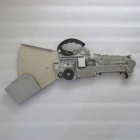
Yamaha CL feeder from 8mm up to 56mm wide


>>Screw thread ball drives?
Same as HP machine yes

>>Encoders?
Same as HP machine feed back servo drive no extra linear encoders planned

>>Aluminium or granite bed?
granite bed  :-DD yes need to place 50000cph
Aluminium machine based on a frame contruction closed working area build in Germany.

>>Existing software like current machines?
yes we use the same

>> What month 'later his year'?
I told you we release END of the year!
« Last Edit: March 24, 2016, 11:02:51 am by Smallsmt »
 

Offline Smallsmt

  • Frequent Contributor
  • **
  • Posts: 598
  • Country: de
Re: SmallSMT - Discussion Thread.
« Reply #83 on: March 24, 2016, 09:01:23 pm »
>>Its odd for a Chinese Company to be building in a high cost location like Germany? Are you ditching your chinese manufaturing?
No we only add a third line of products especially for Europe customers so it's a good solution to build the heavy chassis in Europe to reduce shipping costs.
Our Chinese partner don't need this kind of machine.
And finally we close the gap between the prototyping machines and the smaller professional machine from Juki / Samsung ...
We don't want to build a high speed machine we want a flexible reliable solution for a good price.
And because of the modular design a future upgrade is possible.
 

Offline Smallsmt

  • Frequent Contributor
  • **
  • Posts: 598
  • Country: de
Re: SmallSMT - Discussion Thread.
« Reply #84 on: March 24, 2016, 09:11:17 pm »
The machine stops if the line was accessed and the cover tape not removed.
To repair this problem you need to advance the tape for some parts and feed the tape in the winder again.
You have many options to prevent this case:
1. Arrange the parts on the different feeder sides
2. Take out the cover tape of unused lines
3. Remove the complete tape of an unused line
 

Offline Smallsmt

  • Frequent Contributor
  • **
  • Posts: 598
  • Country: de
Re: SmallSMT - Discussion Thread.
« Reply #85 on: March 24, 2016, 09:13:53 pm »
Our Chinese partner don't need this kind of machine.
Quote

Is SmallSMT a chinese company or a german company?  THis is very cofusing.

I think it's easy to understand we are a Chinese company sales office and manufacturing located in China.
I am German so I stay most of my time in Germany run our support and control the development.
 

Offline Smallsmt

  • Frequent Contributor
  • **
  • Posts: 598
  • Country: de
Re: SmallSMT - Discussion Thread.
« Reply #86 on: March 24, 2016, 09:26:07 pm »
This is a preview for the nozzle changer and vibration feeder function.


https://youtu.be/AYg5mWZnSvk
« Last Edit: March 24, 2016, 09:29:28 pm by Smallsmt »
 

Offline Smallsmt

  • Frequent Contributor
  • **
  • Posts: 598
  • Country: de
Re: SmallSMT - Discussion Thread.
« Reply #87 on: March 24, 2016, 09:37:50 pm »
This problem happens after thousands of access cycles so it is not a real problem!
I always tell our customers all advantages and disadvantages.
 

Offline Smallsmt

  • Frequent Contributor
  • **
  • Posts: 598
  • Country: de
Re: SmallSMT - Discussion Thread.
« Reply #88 on: March 24, 2016, 10:01:40 pm »
Yes the cover tape slips between the 2 saw tooth wheels when it reaches the end.
But on each access cycle the tape moves forward and back for the complete feeder side.
Our advantage is we can control the tape length to open different sized pockets and reduce the overrun by using a short retract length. It is also possible to control the speed and acceleration of the tape for sensitive parts.
The only option is a type of clutch and maybe it's possible to enable using the push feeder head.
But my favorite solution is a modular feeder cassette.
And finally if your machine setup is good the unused tape maybe cut after more than 2500 access cycles.
Remember a normal setup use the West feeder for common parts placements and North / East feeder for special parts. I never had a tape cut on my north feeder.


Offline thommo

  • Frequent Contributor
  • **
  • Posts: 268
  • Country: au
Re: SmallSMT - Discussion Thread.
« Reply #89 on: March 24, 2016, 10:37:24 pm »
MrP,

As I understand, this it what occurs.

There is only one drive for the tape peeler, and it is common for all reels on that side of the machine.

It is a spindle that runs through the centre of the peeler's toothed gear.

Engagement between the spindle and gear is friction only  - there is no key way. Friction is relatively firm I imagine, and sufficient to peel off the tape.

Assuming that only 1 feeder is accessed per component pick then, although the spindle rotates to remove the tape on that feeder, all other tape peelers try to rotate simultaneously. The others can't peel any tape however because their tape is not advanced - no components are removed from their feeder.

So the tension is applied at the jaw where the tape and cover separate. If this happens frequently enough, the tape fatigues at the jaw and finally shears the cover material like a cutting blade.

Michael says it only happens after thousands of cycles, but if you intend leaving your machine setup and loaded for multiple jobs, and other jobs that consume 'thousands' of components, then those unused, or used less frequently become potential candidates I guess.

It doesn't take long to run 'thousands' of components.

So it all depends on your projects.

My main concern is the lack of flexibility is making up the 'mix' of component tape widths. It seems I would lose the advantage of the extra standard maximum qty of feeders right there. Hence I'm looking for a machine that advances tape and cover in sync, and one with individual cartridge feeders ideally.
 

Offline thommo

  • Frequent Contributor
  • **
  • Posts: 268
  • Country: au
Re: SmallSMT - Discussion Thread.
« Reply #90 on: March 24, 2016, 10:56:01 pm »
Michael,

Where does the 'spent tape' actually 'go' after it disappears through the slot?

Who writes the software for these machines - is it you or the machine manufacturer?

Is there a vibrator mechanism in the vib feeder, or does it rely largely on low friction and gravity?

Have you used the Yamaha feeders ever? How noisy are they compared to the solenoid tape peeler/feeder?
« Last Edit: March 24, 2016, 10:58:35 pm by thommo »
 

Offline thommo

  • Frequent Contributor
  • **
  • Posts: 268
  • Country: au
Re: SmallSMT - Discussion Thread.
« Reply #91 on: March 25, 2016, 03:38:10 am »
Michael - a couple of questions that didn't get addressed in previous post.

1.  Can you load both heads from the same feeder, and image them, then place them before returning to the feeders?

2.  Is the idea of 2 cameras to enable different fields of view? What is the largest single component you can image and load? We would like to load modules also if it were possible.

Hi Michael,

Congrats on the new machine. Like MrP said, it's quiet by comparison. Would be great if you were able to replace that solenoid in the peeler with something quieter too.

The video says 0402, but the footprint silk screen description say 0603. It looks like they are 0603s - is that correct?

Any reason that only a single head is used in the demo?
Can you load both heads from the same feeder, and image them, then place them before returning to the feeders?

Is the idea of 2 cameras to enable different fields of view? What is the largest single component you can image and load? We would like to load modules also if it were possible.

Like MrP asked, what are the plans for the tape peeler to stop fatigue and eventually breakage with seldom used components?

Have you considered rearranging the LEDs in the bottom cameras into linear rather than circular design to unify the light better and reduce reflections?

How do I modify the feeder formats/tape sizes? For instance, if I need to add say 2 more 16mm feeders and an extra 12mm feeder for a job.

Here is a 0402 placement video using vision alignment more than 100 pcs placement!

The machine shows all new improvements like West and East tapes are moving now through the machine body.
We have add nozzle changer to all HP machines for free now!

The machine was placing 0402 on a 0603 footprint!
This video was a function check for a customer machine so we didn't use the double head mode.
I thought it could be interesting to show the machine is reliable accessing and placing the small components.

Our vision system needs no even light so we don't improve this.

We have no plans to improve the clear tape winder it will increase the machine price again!

If you need a different feeder configuration you need to buy a different feeder block but it's possible to change.
 

Offline Smallsmt

  • Frequent Contributor
  • **
  • Posts: 598
  • Country: de
Re: SmallSMT - Discussion Thread.
« Reply #92 on: March 25, 2016, 07:15:53 am »
Michael,

Where does the 'spent tape' actually 'go' after it disappears through the slot?
Yes through the slot under the machine there is a tunnel.

Who writes the software for these machines - is it you or the machine manufacturer?
Our Chinese manufacturer / partner

Is there a vibrator mechanism in the vib feeder, or does it rely largely on low friction and gravity?
There is a vibration motor in the bottom

Have you used the Yamaha feeders ever? How noisy are they compared to the solenoid tape peeler/feeder?
Yes I did some test runs the are working nice
 

Offline Smallsmt

  • Frequent Contributor
  • **
  • Posts: 598
  • Country: de
Re: SmallSMT - Discussion Thread.
« Reply #93 on: March 25, 2016, 07:19:24 am »
MrP,

As I understand, this it what occurs.

There is only one drive for the tape peeler, and it is common for all reels on that side of the machine.

It is a spindle that runs through the centre of the peeler's toothed gear.

Engagement between the spindle and gear is friction only  - there is no key way. Friction is relatively firm I imagine, and sufficient to peel off the tape.

Assuming that only 1 feeder is accessed per component pick then, although the spindle rotates to remove the tape on that feeder, all other tape peelers try to rotate simultaneously. The others can't peel any tape however because their tape is not advanced - no components are removed from their feeder.

So the tension is applied at the jaw where the tape and cover separate. If this happens frequently enough, the tape fatigues at the jaw and finally shears the cover material like a cutting blade.

Michael says it only happens after thousands of cycles, but if you intend leaving your machine setup and loaded for multiple jobs, and other jobs that consume 'thousands' of components, then those unused, or used less frequently become potential candidates I guess.

It doesn't take long to run 'thousands' of components.

So it all depends on your projects.

My main concern is the lack of flexibility is making up the 'mix' of component tape widths. It seems I would lose the advantage of the extra standard maximum qty of feeders right there. Hence I'm looking for a machine that advances tape and cover in sync, and one with individual cartridge feeders ideally.

>>So the tension is applied at the jaw where the tape and cover separate. If this happens frequently enough, the tape >>fatigues at the jaw and finally shears the cover material like a cutting blade.

That's not the problem only the slipping between the sawtooth wheels damage the clear cover tape!
 

Offline Smallsmt

  • Frequent Contributor
  • **
  • Posts: 598
  • Country: de
Re: SmallSMT - Discussion Thread.
« Reply #94 on: March 25, 2016, 07:37:07 am »
Quote
1.  Can you load both heads from the same feeder, and image them, then place them before returning to the feeders?

Yes the machine take 2 parts from the same feeder and move to camera adjusting both in two steps

Quote
2.  Is the idea of 2 cameras to enable different fields of view? What is the largest single component you can image and load? We would like to load modules also if it were possible.

We use different magnification to improve precision for small parts.

Quote
Have you considered rearranging the LEDs in the bottom cameras into linear rather than circular design to unify the light better and reduce reflections?

There is no need to improve the light now the vision system has no problems.

Quote
How do I modify the feeder formats/tape sizes? For instance, if I need to add say 2 more 16mm feeders and an extra 12mm feeder for a job.

You buy a special feeder layout at the order time. But if you need to change you can mill a feeder by yourself or buy a different feeder block. It's easy to change it's hold by 6 screws. After changing the feeder block you need to adjust the feeder lines using camera. If you repeat this some times you should add two dowel pins for proper alignment.
Some user did custom feeder blocks by themselves.

And if you dislike the cover tape winder you can add your own solution it's easy to separate from the machine and add a custom solution. Future upgrades possible too.


« Last Edit: March 25, 2016, 07:38:41 am by Smallsmt »
 

Offline Smallsmt

  • Frequent Contributor
  • **
  • Posts: 598
  • Country: de
Re: SmallSMT - Discussion Thread.
« Reply #95 on: March 25, 2016, 02:27:34 pm »
You can visit me in Germany for a demonstration if you need  :)
 

Offline Ichan

  • Regular Contributor
  • *
  • Posts: 86
Re: SmallSMT - Discussion Thread.
« Reply #96 on: March 25, 2016, 02:42:19 pm »
How about you make some demonstration video yourself? A real job from start to end is what people waiting for.

-ichan
 

Offline Smallsmt

  • Frequent Contributor
  • **
  • Posts: 598
  • Country: de
Re: SmallSMT - Discussion Thread.
« Reply #97 on: March 25, 2016, 03:04:49 pm »
I think we have a lot of informations on our website and videos too.
That should be enough!
 

Offline Ichan

  • Regular Contributor
  • *
  • Posts: 86
Re: SmallSMT - Discussion Thread.
« Reply #98 on: March 25, 2016, 03:12:53 pm »
None i saw doing a real assy job, that just not enough to convince anyone.

I do really interested to see it.

-ichan
 

Offline Ice-Tea

  • Super Contributor
  • ***
  • Posts: 3070
  • Country: be
    • Freelance Hardware Engineer
Re: SmallSMT - Discussion Thread.
« Reply #99 on: March 25, 2016, 06:49:02 pm »
You can visit me in Germany for a demonstration if you need  :)

Where in Germany exactly?


Share me

Digg  Facebook  SlashDot  Delicious  Technorati  Twitter  Google  Yahoo
Smf