Author Topic: Teardown : LEM ULTRASTAB 1ppm 600A current sensor  (Read 4008 times)

0 Members and 1 Guest are viewing this topic.

Offline TiNTopic starter

  • Super Contributor
  • ***
  • Posts: 4543
  • Country: ua
    • xDevs.com
Teardown : LEM ULTRASTAB 1ppm 600A current sensor
« on: August 01, 2015, 04:38:32 pm »
Fluxgate technology current sensors madness, welcome little impromptu tear-down.
If you have interesting idea of experiments using such a device, feel free to comment!


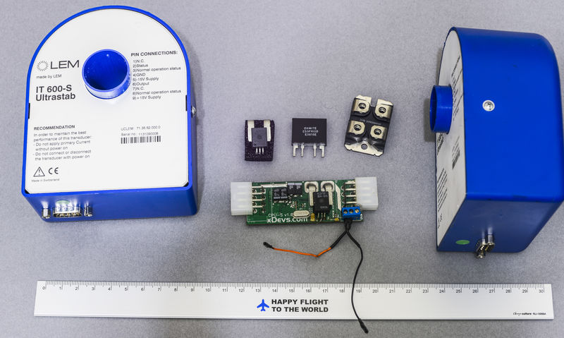
At worklab I have 210A capable DC load and few 400-500A capable low-voltage power convertors, and 150A Tektronix clamp system, so can do something with some beefy amps.
YouTube | Metrology IRC Chat room | Let's share T&M documentation? Upload! No upload limits for firmwares, photos, files.
 
The following users thanked this post: thm_w, Inverted18650

Offline gamer388

  • Newbie
  • Posts: 4
  • Country: fr
Re: Teardown : LEM ULTRASTAB 1ppm 600A current sensor
« Reply #1 on: March 13, 2018, 08:39:40 pm »
Thanks for the teardown and showing us what's inside that current transformer.
I use 4 of these at work with WT1600 Wattmeter from Yokogawa.

I forgot to turn on the power supply for the sensors (+15V and -15V), and now one of my CT is saying about 33 Amp RMS instead of 1A.  |O |O |O
There quite a lot of circuitry inside. I wasn't exepecting that much.


Share me

Digg  Facebook  SlashDot  Delicious  Technorati  Twitter  Google  Yahoo
Smf