Author Topic: Directional coupler 150MHz. Buy or diy?  (Read 13068 times)

0 Members and 1 Guest are viewing this topic.

Offline YansiTopic starter

  • Super Contributor
  • ***
  • Posts: 3893
  • Country: 00
  • STM32, STM8, AVR, 8051
Directional coupler 150MHz. Buy or diy?
« on: December 30, 2017, 11:19:11 pm »
Hello,

since my other thread is not getting much attention as the topic /title/ might  not be so attractive, I've decided to separate this coupler  stuff from it.

I need a directional coupler for the frequency range of 400kHz up to 150 MHz (20dBm max. operating power, coupling 15-20dB). Unfortunately, I can not find any off the shelf component to fit this frequency range. I have found some, but they are no longer made, or have found others with ultra wtf pricepoints.  Can someone recommend where to source this stuff? 

As I need the coupler for a project that I do to learn some new stuff, I have also considered building my own coupler. Below are the results.


I have used an uknown dual aperture core to make a 15dB coupler. It kinda works. Insertion loss about 0.75dB, coupling 15.6dB and directivity 25dB (well... nothing exceptional).  All measured at 118MHz +7dBm only, as my home lab is quite under-equipped regarding RF test equipment. But I plan to further characterize all of these couplers on a VNA - if they let me use it.  ???
This coupler using dual aperture core was wired as following. Winding ratio 1:6. 


I then proceeded to reverse engineer a MiniCircuits ZEDC-15-2B coupler. What I have found interesting, is that it is wired in different manner, like this. Why? What is the difference? Also, the ISOLATED port is terminated using a parallel combination of 50R and some unknown capacitor. What may be the purpose of the capacitor? (apart from the obvious that with increasing frequency the termination impedance gets lower).
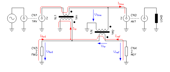

I also plan to make a coupler using two separate toroidal cores. Let's see, what the difference in parameters will be.

How is one supposed to increase the directivity of the coupler?

Thx, Y.

« Last Edit: December 30, 2017, 11:57:01 pm by Yansi »
 

Offline YansiTopic starter

  • Super Contributor
  • ***
  • Posts: 3893
  • Country: 00
  • STM32, STM8, AVR, 8051
Re: Directional coupler 150MHz. Buy or diy?
« Reply #1 on: December 30, 2017, 11:56:37 pm »
Have made a test using two 6mm toroidal cores (couldn't find any smaller). Same 1:6 turn ratio.  It turned out, it works worse.  17.2dB coupling, 1.5dB loss, 21dB directivity.

I then switch the point where the secondary of the IN-OUT transformer is connected, so the circuit corresponded to the second schematic. I did expect something significant to happen, but well... no. No difference. I can barely measure the difference (some fractions of dB of change did that produce).

I then tried adding some small parallel capacitance to the ISO port termination: Small cap (1 puff) does barely anything measurable (using my equipment). 20pF does decrease directivity significantly.

 :-//
 

Offline cdev

  • Super Contributor
  • ***
  • !
  • Posts: 7350
  • Country: 00
Re: Directional coupler 150MHz. Buy or diy?
« Reply #2 on: December 31, 2017, 01:44:40 pm »
It would be nice to know the magnetic material you used for the two aperture core.  Was it from a VHF/UHF balun?

Some work much better than others for VHF/UHF. It looks like you have more turns on yours than I ever have used but you want it to work down to 400 KHz? 


>How is one supposed to increase the directivity of the coupler?

Have you tried using additional beads around/along your parallel wires longitudinally?

-------

As far as using a single toroid, you can use one where the transmission line goes through the middle along the toroids (only) axis. Then the readings are taken from the winding.

Don't know how wideband that would be, that's the setup that seems most commonly used.

Just from my visual impressions of magnetics Ive seen used, small ones are what I would gravitate towards.

You could also use two or more (even numbers) small beads - perhaps glued to one another, like you would a binocular core.

You may (kind of speaking out of my expertise here, so keep that in mind, I don't know the math involved, just guessing at it) need more magnetic in a smaller amount of distance as you go up in frequency?

I would start with more binocular cores (maybe add them end to end first) if you have them. Don't glue anything until you're sure that's the way to go.

I would look at patents. That's the fastest way.

I am just guessing here, suggesting a trial and error process.

How are you doing for magnetic materials?

Keep notes..
« Last Edit: December 31, 2017, 02:00:57 pm by cdev »
"What the large print giveth, the small print taketh away."
 

Offline YansiTopic starter

  • Super Contributor
  • ***
  • Posts: 3893
  • Country: 00
  • STM32, STM8, AVR, 8051
Re: Directional coupler 150MHz. Buy or diy?
« Reply #3 on: December 31, 2017, 02:00:49 pm »
Really do not know the material. It came from an old SAT TV tuner, near from a diode ring mixer. Most likely it was the main mixer in that thing  - i.e. UHF band.

Why do you think I have too much turns? There is minimum turns possible to achieve a 15dB coupler. That is 1 primary turn, 6 secondary turns on each side.

>How is one supposed to increase the directivity of the coupler?

Have you tried using additional beads around/along your parallel wires longitudinally?

I do not understand how should I do that. Can you please explain more, best with a schematic? What is it supposed to do or help with?


Offline cdev

  • Super Contributor
  • ***
  • !
  • Posts: 7350
  • Country: 00
Re: Directional coupler 150MHz. Buy or diy?
« Reply #4 on: December 31, 2017, 02:07:32 pm »
I'm just getting up now and most of my folder of collected stuff is on my other computer. But you know the guy on ebay in the Ukraine who sells the e-field antennas, he also sells one of these broadband directional couplers. I am sure he derived the design from some ham's design, that's what he does he sells implementations of well known designs.

I don't own one or I would be happy to dissect it for science..   

I think that if you can wait a bit I can probably find it if you don't beat me to it. But give what I just told you should get you there.

I've seen the design before and I do think it works.

It uses a lot of beads.

Here is another alternative nicely implemented in a good case but using cheap parts.

http://www.changpuak.ch/electronics/DIY-DualDirectionalCoupler.php

Here is one you can make if you have a suitable two aperture core.  You could also try multiple cores stacked. Note how the windings are at the ends and on the outward side.

its from a digikey article

https://www.digikey.com/en/articles/techzone/2015/apr/tiny-directional-couplers-meet-demands-of-compact-rf-applications

other images- more of the same.

You likely can use other magnetics is what I am getting at. At least that was my interpretation of how that worked

Even though you would think not.. if its designed so the reactance cancels out.
« Last Edit: December 31, 2017, 02:51:34 pm by cdev »
"What the large print giveth, the small print taketh away."
 

Offline YansiTopic starter

  • Super Contributor
  • ***
  • Posts: 3893
  • Country: 00
  • STM32, STM8, AVR, 8051
Re: Directional coupler 150MHz. Buy or diy?
« Reply #5 on: December 31, 2017, 02:26:44 pm »
No I do not no such seller.

But I may now know what you mean by a lot of beads. Those designs are 3dB couplers. Almost useless for my application.

Otherwise I do really not know what do you mean by the beads.
 

Offline cdev

  • Super Contributor
  • ***
  • !
  • Posts: 7350
  • Country: 00
Re: Directional coupler 150MHz. Buy or diy?
« Reply #6 on: December 31, 2017, 03:24:45 pm »
Beads meaning long toroids.  Magnetic material shaped like beads, with a hole in the middle for a single or multiple conductors.

The ebay seller may have been anton_ra0sms (from Russia) but I no longer see the directional coupler.

(Maybe you were right and it doesn't work well?)

He makes and sells the mini-whip antenna kit. And a bunch of other small ham-and-swl related items.

Maybe he has the directional coupler on his web site?

So, not that this would work so well for broadband.. but if you just want to try things like turn ratios and varied configurations out quickly..

For HF you can use one, two or four clip on beads, (usually made out of #43 material) even, for a ghetto style RF transformer.


They lend  themselves to rapid prototyping because you can just clip them shut, making the winding part almost instantaneous.. as long as you don't use that many turns.. (which you likely don't need as with a longer magnetic you usually need fewer turns)

 Also, you can just stack them (going from two side by side to four side by side for example) to increase the inductive reactance. That's what I was getting at by "more beads". 

If like me you have a bunch around, that is good for rapid prototyping because you can wrap the already twisted wires around an open core much faster than laboriously threading them through a closed one.
« Last Edit: December 31, 2017, 03:40:21 pm by cdev »
"What the large print giveth, the small print taketh away."
 

Offline YansiTopic starter

  • Super Contributor
  • ***
  • Posts: 3893
  • Country: 00
  • STM32, STM8, AVR, 8051
Re: Directional coupler 150MHz. Buy or diy?
« Reply #7 on: December 31, 2017, 04:20:14 pm »
Please do not edit posts that somebody have already replied to. It makes a mess. Now I see you edited post I have already responded to. 

As you may have already seen, I have made a couple of custom couplers and posted back the results. I find it not necessary to post images from google how it is supposed to be connected or how does these parts usually look like. I have already gone through all of that. I am instead in the situation where I need to make the couplers behave better in terms of their performance, but can not find any clues to do so. 

I do know how a ferrite bead looks like. I do not know how to add one in my existing coupler design you see above? That just does not currently make any sense to me. I think you did say I have to add those? Hence asking how and where.
 

Offline cdev

  • Super Contributor
  • ***
  • !
  • Posts: 7350
  • Country: 00
Re: Directional coupler 150MHz. Buy or diy?
« Reply #8 on: December 31, 2017, 07:04:48 pm »
http://www.sdr-deluxe.com/publ/vch_most_dlja_raboty_hiqsdr_v_kachestve_vna/1-1-0-3


Must translate from Russian but the picture is clear on its construction.

The cores are Amidon BN43-2402.

"What the large print giveth, the small print taketh away."
 

Offline YansiTopic starter

  • Super Contributor
  • ***
  • Posts: 3893
  • Country: 00
  • STM32, STM8, AVR, 8051
Re: Directional coupler 150MHz. Buy or diy?
« Reply #9 on: December 31, 2017, 07:27:33 pm »
Someone already posted an ebay auction with this into this topic (or maybe the other one?).  But this kind of construction yields a 3dB coupler, doesn't it? I am more interested into how to construct a high directivity (more like my 25dB ghetto style gizmo) coupler with like 15 or 20dB coupling.
 

Offline cdev

  • Super Contributor
  • ***
  • !
  • Posts: 7350
  • Country: 00
Re: Directional coupler 150MHz. Buy or diy?
« Reply #10 on: December 31, 2017, 08:27:09 pm »
 I don't know. To be honest with you, i've seen similar designs before, just going on my memory, that were supposed to be quite good, but I am not sure this is the same design as them without going through dozens of files looking for the ones I saved before and I am just too busy right now to do that.

I can't see how it would only be 3db.


This design yields excellent performance-

Here is what I recommend. It really is true that a picture says a thousand words. You should put in a few words describing construction details, ("RF bridge" seems to do well!) - do a google search , look at the image results, you'll save a lot of time that way, you should easily be able to find the one that looks similar and then you should be able to find out its performance.

Just doing that I found a great many possibilities. This is a high performance device you could build yourself if you have a bunch of the proper binocular cores and the interconnects, etc. lying around.

Look, found this:

« Last Edit: December 31, 2017, 08:52:14 pm by cdev »
"What the large print giveth, the small print taketh away."
 

Offline yl3akb

  • Regular Contributor
  • *
  • Posts: 100
  • Country: lv
Re: Directional coupler 150MHz. Buy or diy?
« Reply #11 on: December 31, 2017, 08:43:04 pm »
Someone already posted an ebay auction with this into this topic (or maybe the other one?).  But this kind of construction yields a 3dB coupler, doesn't it? I am more interested into how to construct a high directivity (more like my 25dB ghetto style gizmo) coupler with like 15 or 20dB coupling.

With those resistor values it is 6 dB coupler (with 6 dB coupling, 6 dB 'main line' loss and theoretically ideal directivity). But like cdev said, it does not have to be only one value. Here is publication which describes design of such couplers with different loss/coupling values (of course it is compromise between two values due being resistive type)
 

Offline cdev

  • Super Contributor
  • ***
  • !
  • Posts: 7350
  • Country: 00
Re: Directional coupler 150MHz. Buy or diy?
« Reply #12 on: December 31, 2017, 09:00:36 pm »
I don't understand what parameter you are referring to with 3 db/6db, could you explain as if you were speaking to an 15 year old or so?
"What the large print giveth, the small print taketh away."
 

Offline G0HZU

  • Super Contributor
  • ***
  • Posts: 3015
  • Country: gb
Re: Directional coupler 150MHz. Buy or diy?
« Reply #13 on: December 31, 2017, 09:39:42 pm »

Minicircuits do the PDC20-3 models and they cost under $30?

https://ww2.minicircuits.com/pdfs/PDC-20-3BD+.pdf

200kHz to 250MHz, 20dB coupling, <0.3dB loss and 40dB directivity.
 

Offline YansiTopic starter

  • Super Contributor
  • ***
  • Posts: 3893
  • Country: 00
  • STM32, STM8, AVR, 8051
Re: Directional coupler 150MHz. Buy or diy?
« Reply #14 on: December 31, 2017, 10:39:21 pm »
Yeah, these are decent. However $30.. I do not steal or shit money yet.  ;D

Also only seems to be available on the MiniCircuits website. Add shipping costs and it'll cost twice that  :( And also there is a $4 fee for being european. So $34 a piece plus shipping.   :-\

I'd rather continue making diy ones. Just need to find the right recipe for better directivity  >:D


Offline rhb

  • Super Contributor
  • ***
  • Posts: 3481
  • Country: us
Re: Directional coupler 150MHz. Buy or diy?
« Reply #15 on: January 01, 2018, 03:46:10 am »
How is one supposed to increase the directivity of the coupler?

The following is from the ARRL book, "Introduction to Radio Frequency Design" by Wes Hayward, W7ZOI

[edit]

I also found this:

http://www.armms.org/media/uploads/1335954969.pdf

and an MSEE thesis:

https://scholarsmine.mst.edu/cgi/viewcontent.cgi?article=6108&context=masters_theses


« Last Edit: January 01, 2018, 05:49:52 am by rhb »
 

Offline yl3akb

  • Regular Contributor
  • *
  • Posts: 100
  • Country: lv
Re: Directional coupler 150MHz. Buy or diy?
« Reply #16 on: January 01, 2018, 10:17:11 am »
I don't understand what parameter you are referring to with 3 db/6db, could you explain as if you were speaking to an 15 year old or so?

Like I said: its coupling factor and main line loss. These type couplers are usually used to measure reflected signal and it would be little unusual to use it other way around (I understand, that Yansi wants to use coupler for forward coupling), but it would work! If we use designations of schematic You posted at #8: input would be 'vswr_out', 'hf_input' - output, 'ref' - 50ohm resistor, and  'DUT' would be forward coupled port, signal of which which would stay constant with varying load at output (or 'hf_input') port.
 

Offline Wolfgang

  • Super Contributor
  • ***
  • Posts: 1775
  • Country: de
  • Its great if it finally works !
    • Electronic Projects for Fun
Re: Directional coupler 150MHz. Buy or diy?
« Reply #17 on: August 08, 2018, 12:16:33 am »
Well, I made one myself based on an old ARRL article. It works from low HF to 220MHz,
and I built one with stright outputs and with detector diodes.

https://electronicprojectsforfun.wordpress.com/rf-module-gallery/swr-bridges/
 

Offline cdev

  • Super Contributor
  • ***
  • !
  • Posts: 7350
  • Country: 00
Re: Directional coupler 150MHz. Buy or diy?
« Reply #18 on: August 11, 2018, 02:29:42 pm »
Is it possible to make and use a directional coupler for wires in general (including Ethernet)?

This would also be useful for hunting down sources of RFI that was riding on wires of any kind..

 I am thinking it could likely be done with clip on toroids around the lines.
« Last Edit: August 11, 2018, 02:31:58 pm by cdev »
"What the large print giveth, the small print taketh away."
 

Offline tkamiya

  • Super Contributor
  • ***
  • Posts: 2178
  • Country: us
Re: Directional coupler 150MHz. Buy or diy?
« Reply #19 on: August 11, 2018, 03:21:19 pm »
Just a few cents....

I made few myself and scanned it.  The circuit looked easy but I guess there is a lot of know-how that goes into it.  It was difficult to get it to respond uniformly (flat).  In the end, I bought one.  It would be an interesting project but at that time, I just needed one that works.
 

Offline YansiTopic starter

  • Super Contributor
  • ***
  • Posts: 3893
  • Country: 00
  • STM32, STM8, AVR, 8051
Re: Directional coupler 150MHz. Buy or diy?
« Reply #20 on: August 11, 2018, 04:36:02 pm »
Well that is an interesting idea. Not sure about your requested bandwidth (due to the clip-on ferrite material being rather very lossy at RF) but I'd give that a go.
 

Offline cdev

  • Super Contributor
  • ***
  • !
  • Posts: 7350
  • Country: 00
Re: Directional coupler 150MHz. Buy or diy?
« Reply #21 on: August 11, 2018, 06:08:40 pm »
(Just ruminating out loud) gee, I wonder every time I see these meters, what the lowest amount of power which could be used to do these kinds of measurements?

I wonder what the minimum signal practicable would be..

I guess I am wondering if the power emitted by a sig-gen would be enough to deflect them?

If any of these directional couplers work with the power generated by a cheap signal generator only?

(i.e. power levels that are so low they are not considered RF transmission of any kind?)

Maybe an oscilloscope would be okay within its frequency range?

(I'm thinking of the nonlinearity problem with diodes and low voltages.)

Network analyzers do something like that.
« Last Edit: August 11, 2018, 06:23:24 pm by cdev »
"What the large print giveth, the small print taketh away."
 

Offline T3sl4co1l

  • Super Contributor
  • ***
  • Posts: 21657
  • Country: us
  • Expert, Analog Electronics, PCB Layout, EMC
    • Seven Transistor Labs
Re: Directional coupler 150MHz. Buy or diy?
« Reply #22 on: August 11, 2018, 06:28:03 pm »
Is it possible to make and use a directional coupler for wires in general (including Ethernet)?

This would also be useful for hunting down sources of RFI that was riding on wires of any kind..

I am thinking it could likely be done with clip on toroids around the lines.

The gold standard method is a CDN (coupling-decoupling network).  For telecom pairs (like Ethernet), you use a TLT wired as CT choke to get a midpoint of the pairs (without causing too much disturbance to the (AC coupled) signal on the pairs themselves -- thus, this works for Ethernet, say, but changes are necessary to do the same for POTS), and add a CMC to the pair to isolate the common mode from the two ports of the network.  Put another way: it's a bias tee for the common mode of a pair.
https://www.seventransistorlabs.com/Precompliance/

A clamp sensor (can be a mere current transformer with relatively high gain) can indeed help for sniffing, and is actually used directly in some standards.

Tim
Seven Transistor Labs, LLC
Electronic design, from concept to prototype.
Bringing a project to life?  Send me a message!
 

Offline joeqsmith

  • Super Contributor
  • ***
  • Posts: 11708
  • Country: us
Re: Directional coupler 150MHz. Buy or diy?
« Reply #23 on: January 16, 2021, 06:04:41 am »
Slightly exceeded the 4W max limit.  The main winding was all that was left.   The new wire is dark green and was soldered to the pads rather than welding.   My eyes are no longer good enough and I had to wrap it under the microscope using tweezers.   Had to remove the PCB to work on it. 

https://www.minicircuits.com/pdfs/ZFDC-20-3.pdf


Share me

Digg  Facebook  SlashDot  Delicious  Technorati  Twitter  Google  Yahoo
Smf