Author Topic: Fractal Antennas  (Read 4591 times)

0 Members and 1 Guest are viewing this topic.

Offline raspberrypiTopic starter

  • Frequent Contributor
  • **
  • !
  • Posts: 358
  • Country: us
Fractal Antennas
« on: January 14, 2017, 07:55:02 am »
This is an interesting topic. Basically this guy made a fractal antenna and compared it to see which is better. Do you think that his results were right? I wonder if his fractals didn't perform as well because they are sensitive to small details like asymmetry having a huge effect on performance. What I'm trying to figure out is what makes it work at which frequency? Is it the angles the length the length of each segment? I have one of my own I'm making but I don't have access to a SWR meter or much else besides plugging it in and seeing if it works. The wikipedia page is lacking.


http://www.antenna-theory.com/antennas/fractal.php


Antenna designers are always looking to come up with new ideas to push the envelope for antennas, using a smaller volume while striving for every higher bandwidth and antenna gain. One proposed method of increasing bandwidth (or shrinking antenna size) is via the use of fractal geometry, which gives rise to fractal antennas.
Fractals

Fractals are those fun shapes that if you zoom in or zoom out, the structure is always the same. They have wild properties, like having a finite area but infinite perimeter. They are often constructed via some sort of iterative mathematical rule, that generates a fractal from a simple object step by step. In the last section of this page, we will do that in designing a fractal antenna.

Examples of fractal geometry are shown in Figures 1 and 2:
example of a fractal geometry

Figure 1. A snail like fractal geometry.

triangle fractal geometry

Figure 2. Triangle Fractal Geometry.
Fractal Antennas

Since fractals show up in the real world of nature (snail shells, leaves on a tree, pine cones), why not see if they perform well as antennas? It turns out that if you make antennas with fractal shapes, they will radiate, and often have multiband properties. Exmaples of these antennas are below:

examples of fractal antennas

Figure 3. Triangle Fractal Geometry. Upper Left: Patch Antenna Fractal. Lower Left: Monopole Fractal. Lower Right: Bowtie Monopole Fractal Antenna .

Analysis of Fractal Antennas

The argument on why you might want to use a fractal geometry essentially is "if you have a very complex shape, you will allow for many electric current modes (i.e. distinct current distributions) to exist, all of which can give rise to radiation. As a result, a complex fractal antenna should have very wide bandwidth, and because the lengths of the traces are very long the antenna will be smaller than otherwise need to be".

This is a valid argument, and some people love fractal antennas. It certainly sounds intelligent. Having never encountered a situation where a fractal antenna has been used, I decided to build up a triangle fractal antenna and test it, as I evolve it from a simple bowtie antenna through iterations to become a fractal. Let's see what happens. The length is approximately 7 inches (18cm) and the width is about 3.5 inches (9cm).

I start with a simple bow-tie antenna as shown in Figure 4:

iteration 0 of my fractal antenna

Figure 4. A bowtie antenna - this is our baseline antenna for comparison.

I will then use an iteration approach, each time making the triangle antenna approach the geometry of the fractal in Figure 2. The first step is to remove a couple triangles, such that we have 3 idential triangles on each side of the antenna:

iteration 1 of my fractal antenna

Figure 5. Iteration 1 of the evolution from bowtie to fractal antenna.

We then repeat that same process on each triangle - this is the iteration method that will give rise to the fractal. Iteration 2 makes for 18 total triangles that make up the antenna:

iteration 2 of my fractal antenna

Figure 6. Iteration 2 of the evolution from bowtie to fractal antenna.

Finally, for fun we'll add antoher iteration, ending up with 54 total triangles, and an ever more complicated structure approaching a fractal:

iteration 3 of my fractal antenna

Figure 7. Iteration 3 of the evolution from bowtie to fractal antenna.

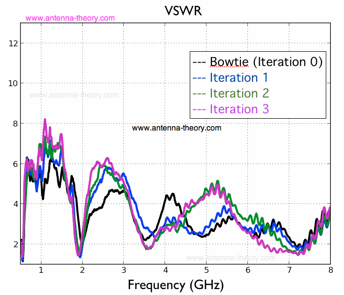
Now, to test these antennas, we will measure the VSWR and the antenna efficiency at each stage and compare the results. The VSWR results are shown in Figure 8:

vswr of fractal antenna

Figure 8. VSWR for the Bowtie and Iterations 1-3 of the fractal Antenna.

Figure 8 shows that the baseline case and the antennas of Figures 5-7 (iterations 1,2,3) are not significantly different. There are some frequency regions where the fractals are better (such as around 4 GHz), and some places where the baseline case is better (about 5 GHz). From Figure 8, the conclusion is that there is no fundamental benefit to performing the fractal iteration over a bowtie antenna from a VSWR (mismatch loss) perspective.

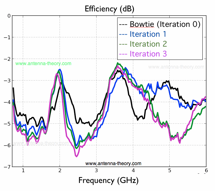
Next, we look at the antenna efficiency. This is shown in Figure 9:

fractal antenna efficiency

Figure 9. Antenna Efficiency for the Bowtie and Iterations 1-3 of the fractal Antenna.

Figure 9 is very interesting. At the low frequencies (700MHz-1.5 GHz), the baseline case performs better than the fractals. In fact - as each iteration occurs on the bowtie geometry, the low frequency antenna efficiency gets worse. This is very interesting. One of the reasons fractal antennas are touted as valuable is that they are able to shrink the size of the antenna - if this were the case, the lowband efficiencies should get better with each iteration.

There are some regions where fractals appear to have better performance - 2 GHz and 3.5 GHz (for instance) - but it is not significantly better. In fact, there are wide bandwidths where performing the iteration to make the fractal actually degrades the antenna efficiency. Hence, this data shows that implementing a triangle fractal (of Figure 2) as an antenna adds little to no value, and can often degrade performance.

This is very interesting. It implies that a lot of the talk around fractal antennas is in fact hype. If you have a volume available to you for antenna design, it is best to use a large conducting area (as in Figure 5 - no cut outs or meandering). It is not advantageous to increase manufacturing and design complexity by creating fractals. This may explain why fractals are not widely used.

There is some talk of fractals used in defense applications. I honestly am not sure if this is because the defense industry is significantly less (or more) intelligent than other industries (due to government ownership), or if there exists some advantages to some types of fractal antennas. But it just goes to show - test things out and see for yourself!

I hope you've enjoyed this article and learned a thing or two about fractal antennas. Tell your friends!

Antennas List

Antennas (Home)

Smith Chart

"Fractal antennas" by antenna-theory.com has been copyrighted. Copyright antenna-theory.com, 2009-2013.
I'm legally blind so sometimes I ask obvious questions, but its because I can't see well.
 

Offline Ammar

  • Regular Contributor
  • *
  • Posts: 154
  • Country: au
Re: Fractal Antennas
« Reply #1 on: January 14, 2017, 08:04:18 am »
Fractal antennas appear to be hype, as the article demonstrates. Check with antenna simulation software if you are unsure. There are plenty of free and non-free packages available.
 

Offline T3sl4co1l

  • Super Contributor
  • ***
  • Posts: 21675
  • Country: us
  • Expert, Analog Electronics, PCB Layout, EMC
    • Seven Transistor Labs
Re: Fractal Antennas
« Reply #2 on: January 14, 2017, 10:04:57 am »
There are lots of fractals, but only a subset of them are useful for radio frequency purposes.

Fractals that have a linear aspect (like a fern fractal with no twist), and geometric self-similarity (i.e., each element is an equal ratio bigger or smaller than the adjacent elements), have wide bandwidth, linear polarization, and directivity along the axis (prime example: log periodic).

Fractals with a radial aspect have directivity along the symmetry (i.e., radially), linear polarization, and wide bandwidth.  Prime example: conical dipole.  (Note that a cone is continuous, not discrete.  At any rate, any conical sub-unit (i.e., not a frustrum) of a cone, is still a cone, so it's geometrically self-similar, without using discrete elements or stages!)

Fractals with a tangential aspect have directivity along the symmetry (i.e., axially), circular polarization, and wide bandwidth.  Prime example: spiral antenna.  (A logarithmic spiral is geometrically self-similar, but an Archimedean spiral also has a similarly useful property of being self-dual, when dimensioned correctly.)

You can mix and match to get other interesting shapes, like the conical spiral, which has circular polarization and linear directivity.

Self-dual antennas have the useful property that their feedpoint impedance is constant and equals Zo/2, i.e., around 188 ohms.  Well, it may not be particularly useful compared to traditional 50 or 300 ohm feedlines, but that's just a balun away.

Fractals that don't have these E&M-friendly characteristics should not be expected to exhibit useful performance compared to simpler designs.  In the above plots, the simple bowtie seems to perform better in some properties!

Curve fractals, like the Koch snowflake, lie on the dubious border between fractals that are practical, and those that are useless.  The property that every sub-segment is at a different angle, length and distance from every other part, means that the radiation pattern won't be much of anything: just lumpy.  If you wanted directivity, you won't get it (and the pattern will vary with frequency); if you didn't want directivity (to get closer to an isotropic antenna), you'll end up with holes.

And if you're going for small antennas and narrow bandwidths, the fractal structure matters absolutely none -- the sharp corners of your intricately cut fractal, can only be "felt" by waves of a comparable wavelength.  For such an application, you can't spare the space for an antenna ten times (or more) longer than your operating wavelength!  For "short" antennas, the shape matters very little indeed; practical designs are usually a whip, or tab, or patch, with some tuning / matching circuitry at the bottom (which may be part of the antenna geometry itself, like the "gamma match" connection).

So the only applications where fractal antennas make sense, are those with very high bandwidth demands (more than an octave), and low to modest directivity.

Tim
Seven Transistor Labs, LLC
Electronic design, from concept to prototype.
Bringing a project to life?  Send me a message!
 

Offline KD0CAC John

  • Frequent Contributor
  • **
  • Posts: 707
  • Country: us
Re: Fractal Antennas
« Reply #3 on: January 14, 2017, 03:56:03 pm »
With a lack of info - from you not what you copied & pasted , such as are you receiving and or transmitting ?
Frequencies , power etc.
Then with no test gear , SWR meter - really about the cheapest most common single thing widely available as cheap as $5 - 10 and up .
Also no idea of any about antenna theory - at least that the length of the wave of a frequency in question - relative to size of elements .
I applaud the interest , but you may need to backup and get some basics 1st , of course many of us bite off something that gives us the interest / questions to ask when we do go back to find the basics -  REMEMBER the only stupid question is the one not ask ;)
The as mentioned this can be a rabbit-hole !
At least as I know , Chip one of the main people I know of , is a ham and hangs out of QRZ forums , and PBS / maybe Nova , did a program on fractals and he was one of the people mentioned , has tried to talk about them on QRZ , but has been harassed a lot there , maybe part of it is that he is a entrepreneur - has patents and is trying to make money with , so is not totally forth coming with all info as a result .
They are being used from what I have gathered with small devices like cell phones , higher frequencies .
Many of the hams are non believers , which is a hole another issue .
I have not come across of any used for HF frequencies where they are needed when ham wants to get on 160 meters from an apartment hi-hi , 1/4 wave length depending , 133 feet . 
 

Offline Lightages

  • Supporter
  • ****
  • Posts: 4314
  • Country: ca
  • Canadian po
Re: Fractal Antennas
« Reply #4 on: January 15, 2017, 03:15:35 am »
AFAIK, fractal antennas are just snake oil. I had a run in with a nut case on antenna newsgroups, fractenna?, who made all kinds of claims and just did the insult and run tactic when pushed for real information. Fractals can't change the laws of physics.
 
The following users thanked this post: TheBay

Offline slicendice

  • Frequent Contributor
  • **
  • Posts: 365
  • Country: fi
Re: Fractal Antennas
« Reply #5 on: January 15, 2017, 01:13:25 pm »
Though fractals can be extremely useful in many applications, I don't see the benefit of adding extreme calculation complexity to antenna design using fractals.
 

Online ConKbot

  • Super Contributor
  • ***
  • Posts: 1384
Re: Fractal Antennas
« Reply #6 on: January 18, 2017, 04:54:40 pm »
Can't beat physics. Your incoming power/area is fixed on a rx antenna, so your gain can only be so high with a certain effective aperture.  So a "perfect" 10mm x 10mm 2.4 ghz antenna may perform the same as a 30x30mm patch with a  lame 11.1% radiation efficiency.   Like others said, wideband and low gain is where they are applicable.
 

Offline Kelbit

  • Regular Contributor
  • *
  • Posts: 58
  • Country: ca
Re: Fractal Antennas
« Reply #7 on: January 22, 2017, 10:25:02 am »
Fractal antennas do actually have some use, they aren't "snake oil." I have fabricated a few myself (both Koch loops and Hilbert dipoles) and tested them with a VNA. There are also lots of papers covering cases where people have designed and optimized them in software like CST and the fabricated them in the real world. Properly designed and matched, they do enable you to squeeze a tiny bit more performance out of a physically small antenna.

Of course, you can't escape the Chu limit, which is where a lot of the confusion with small antennas lies. There is a hard, physical limit, end of story.
 
The following users thanked this post: orolo

Offline KD0CAC John

  • Frequent Contributor
  • **
  • Posts: 707
  • Country: us
Re: Fractal Antennas
« Reply #8 on: January 22, 2017, 01:55:48 pm »
I suck at the math side of this , but I get the implication that this is why they would be problematic for HF / ham ?
 

Offline T3sl4co1l

  • Super Contributor
  • ***
  • Posts: 21675
  • Country: us
  • Expert, Analog Electronics, PCB Layout, EMC
    • Seven Transistor Labs
Re: Fractal Antennas
« Reply #9 on: January 22, 2017, 10:59:09 pm »
They're not really applicable to a lot of HAM work because the amateur bands are very narrow.  It's if you want many bands without touching anything, and don't have the space for a big one like a log periodic, conical dipole or log spiral.

Tim
Seven Transistor Labs, LLC
Electronic design, from concept to prototype.
Bringing a project to life?  Send me a message!
 

Offline Ivan7enych

  • Regular Contributor
  • *
  • Posts: 158
  • Country: ru
    • My astronomy projects
Re: Fractal Antennas
« Reply #10 on: February 17, 2017, 10:26:39 am »
Looks like useless toy.  VSWR is almost everywhere > 2..3.

I've made a Log periodic antenna - it worked much better, VSWR < 3 in a wide freq range.

This site have a good example
http://www.antenna-theory.com/antennas/wideband/log-periodic-dipole.php
« Last Edit: February 17, 2017, 10:31:18 am by Ivan7enych »
 

Offline T3sl4co1l

  • Super Contributor
  • ***
  • Posts: 21675
  • Country: us
  • Expert, Analog Electronics, PCB Layout, EMC
    • Seven Transistor Labs
Re: Fractal Antennas
« Reply #11 on: February 17, 2017, 05:57:59 pm »
Looks like useless toy.  VSWR is almost everywhere > 2..3.

That's a good thing -- well, it can be.  If it's modest (2-4) but stable (no crazy peaks or dips), over a wide range, that suggests only a matching error, which is easily solved with a balun (or un-un, or whatever).  This is characteristic of self-dual antennas (like the conical dipole and planar spirals).

The VSWR is still pretty useless in the OP example though :P

Tim
Seven Transistor Labs, LLC
Electronic design, from concept to prototype.
Bringing a project to life?  Send me a message!


Share me

Digg  Facebook  SlashDot  Delicious  Technorati  Twitter  Google  Yahoo
Smf