Assuming RF above 500MHz and a VNA becomes a very important tool to be able to do many needed measurements in an effective and reliable way.
Then measured 50+j0 Ohm, it never happens for an embedded antenna or radio.
Both antenna and radio impedance are with freq. irregular complex impedance curves, never a straight line.
Data sheet may say radio interface is 50 or 100 Ohm. Only thing to be sure about, impedance value is different for each PCB design and is seldom close to assumed ideal value.
PCB is affecting radio impedance. Vcc decoupling, Vcc trace lengths, ground trace lengths, PCB ground impedance, length and width of all RF-traces are a few of the impedance factors.
Match both radio and antenna to 50+j0 Ohm and then connect? Forget it. It only create losses by adding unnecessary impedance poles making a in total less good matching network..
I do design embedded antennas and impedance matching network for living. In average do I create a matching network once every day. Mostly wideband matching, GPRS 1-3 GHz, with components in size 0201-0402 and I do always also design the antenna as well.
As both input and output impedances are irregular over frequency must designed matching network also be that to create best conjugate match.
In below description how of a possible work flow when doing this kind of job is a software used which I have written. It is a specific kind of software that adds live functions to a VNA.
This kind of software, no need to use same as me! There are a number of more or less similar software such as Optenni and Betamatch but in this case is AnTune used as something must be used to describe the work flow of PC aided VNA impedance matching.
It is often a bit expensive software but pays for it self within few weeks as it at least doubles an RF engineer productivity and quality of job when doing embedded antenna and matching work. It also reduced lab time and even reduces time needed in anechoic chamber.
Few software have that short time of ROI.
This kinds of software which works as extension to VNA are simple to use because if you is familiar with how to handle a VNA is also this software familiar, no learning curve. you is productive within minutes after first seen this software..
Following steps can be done in several ways, with aid of software of above described type as a helping tool.
It is possible to use any software that can do complex math calculations but maybe not as practical.
Using ruler an a lead pencil directly at printed Smith chart is also possible. I have done it several times for a single frequency. For wideband irregular signals, is it way too time consuming.
The helper software reads data directly from VNA and present it in a PC in similar way as it is shown at VNA but with some new math functions added.
A interface between PC and VNA must exist if live data should be able to be shown at PC screen. Typical exist interfaces over GPIB/USB/LAN but some VNA interfaces are too slow to be usable or do not provide any standard protocol.
A typical impedance matching scenario is that a prototype antenna since before is designed at a PCB with aid of CU tape. This design is transferred to Gerber format and added to a radio PCB.
PCB have after few weeks now been printed and radio chip is implemented active and working but not yet matched to antenna. Space is reserved as a PI or T network.
Antenna impedance for printed PCB is maybe not exactly same as when cu-tape was used to create antenna pattern but that is seldom critical, as long as antenna impedance is reasonable in same range as the prototype antenna. Minor changes will be taken care of by matching circuit.
Typical tuning/matching job is done by me as following:
1. Solder 10 cm semi-rigid cable at DUT near where location is for an intended matching network. Other end of cable have an SMA connector. Cable braid have got ferrit tubes to avoid extending ground plane of DUT, which else can affect measured antenna impedance.
2. At VNA is a 1 meter long high quality coaxial cable connected. At end of this cable is 10 cm long cable connected of same type as was soldered at DUT, but this one have SMA connectors in both ends.
3. Whole cable length is calibrated, 1m+10 cm. Idea to include last 10 cm is to include same type of reactive losses as for soldered pigtail cable. Port extension part is not important at the moment.
4. Remove 10 cm cable extension and connect 1meter cable to coaxial cable soldered to DUT.
5. Cable at DUT should have its center wire 2-3 mm extended above a soldering pad at intended location for matching network but it is not yet soldered to anything, it open circuit.
Now startup AnTune or corresponding software.
6. in software, press button "auto port forward" for automatic calibration of amplitude and phase for OPEN. It is automatically selected OPEN as center wire is unsoldered.
7. Usually with an exacto, shortcut center wire to braid and press same button again for automatic calibration of SHORT. Those both steps makes current setup calibrated with high precision. both in phase and amplitude.
8. Now solder center wire at matching network such that RX and TX circuit can be measured. If needed in software, can measured impedance curves be weighted for Tx and Rx, as it never is same impedance for TX and RX.
It is also possible to tell software if harmonics should be taken in account as part of filtering/matching network. Especially as in many cases do it exist several solutions that provide same matching impedance but suppress harmonics rather different.
8. Next step press button in software that saves current Tx and/or Rx impedance.
9. In software, set this saved impedance as reference impedance instead of assumed 50 Ohm. Software will automatically assume that conjugate matching of a network is next step.
10 Move coaxial center pin from direction radio to instead direction antenna, including empty places for a matching network (typical a pi or T network.)
11. Select in software actual filter topology and size/brand of tuning components.
12. Software will from now on calculate optimal network. If surrounding near antenna is changed due to hand effect or load of enclosure is matching network dynamically updated..
13a. Assume that software present a VSWR that seems to meet requirements for a specific setup. If PCB RF-ground is very low loss and distance between each component in matching network only add minor phase error can now matching network be soldered at PCB.
In software verify that real matching network results in same VSWR as predicted by VSWR calculated using virtual components.
13b, this step is when 13a fails. 13a do mostly work well but if optimal result is important or PCB not is ideal, especially in combination with frequencies above 1-2 GHz must we modify a bit how to perform a high quality matching job.
Modification is to implement matching minor network in steps. Solder just matching component closest to antenna, and in software check that soldered value is optimal. If not optimal adjust value a step up or down, according to software directive.
When satisfied, do same procedure with next two components, one at the time.
14 Done.
A bit long description, it takes longer time to read then practically perform. Time nedded is usually 10-15 minutes to implement a matching network of PI or T type and when job is is finished are all curves saved for documentation and matching network will be saved as a BOM-list.
Report, graphical curves and BOM is saved as a html file and curves can be saved as touchstone files for further calculations and reference if something changes in production of further batches of PCB.
This kind of software main advantage is else when designing prototype antenna in combination with matching network. For every minor adjustment of antenna shape will total resulting VSWR including for the moment optimized network be shown. This part is also of value when tuning for widest range of handling different surroundings near antenna, held in free space, hand-held..
The software I use provide a bit unique function which is of good help when designing antennas.
A very efficient antenna is not necessarily something 50 Ohm, which anyway not is of interest if optimal matching radio circuit neither provide a 50 Ohm interface.
But how to know if a particular antenna design is a good radiator and not just more or less a resistor? Rough estimation can be done by doing practical RSSI measurements. Long experience what usually work is also a good help.
For reliable results with somewhat precision is an anechoic chamber needed to measure antenna efficiency. It is not for every RF-lab, a such chamber is expensive, big and it takes time to do measurements.
What makes this software a bit unique is that it can measure antenna efficiency directly at lab bench, dynamically and without delays with precision similar to an anechoic chamber, a few % +/- but now 10 times/second or depending on sweep speed of the VNA.
One sweep in anechoic chamber needs you to stop development process at lab bench and waiting for 30 minutes for this single sweep and then process data to find antenna efficiency.
All software functions together makes it a very complete tool if working with embedded antennas or RF filter matching in general.
However most functions are rather useless if you not have a VNA with GPIB compatible interface (USB/LAN/GPIB) or an VNA such as from Copper Mountain Technologies which provide a VISA compatible interface directly in PC or over LAN.
All above described functions can be done in Excel or many RF simulator tools as well, but not as live data at PC screen.
Non live data, manually handled, makes job process much slower. Instead of 10-15 minutes to create same level of optimizing is a more manual way maybe jobs for weeks if same optimized goal is needed.
Some measurement curves from my latest impedance matching for a BT 2.4 GHz unit in order how I did the job:
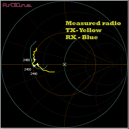
Measured RX impedance is not exactly same as TX impedance but both curves are unusual similar. From these two curves will I create a third curve which is average of these both. Function to do this exist in software.
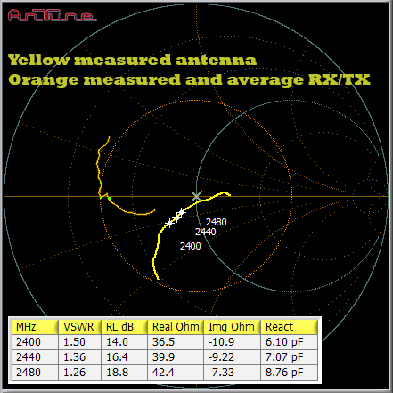
Average radio impedance and now is also antenna impedance measured. Antenna is measured with same coaxial cable as it is only center wire that is moved between two pads in reserved space for matching network.
Table refers to yellow curve.
Matching component family is selected in AnTune as S-parameters differs between brand and physical size of component for same value. In this case did I select Murata 0402 with wire-based inductors (type LQW15).
Conjugate of average impedance is now set as reference impedance instead of 50+j0 Ohm (the cross in center of Smithchart becomes a curve).
Software create automatically an optimized matching network and resulting impedance (antenna+network) is shown as yellow curve.
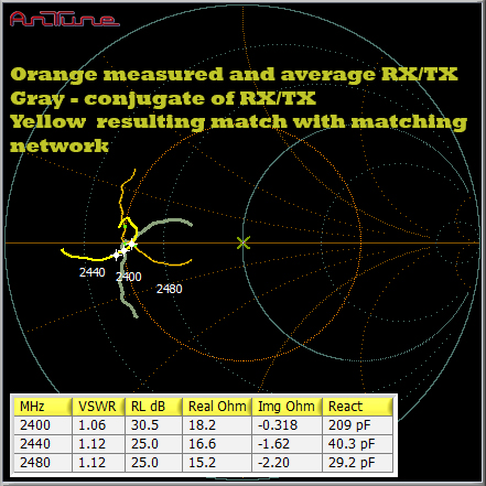
Within actual frequency band is yellow curve now very close to impedance goal represented by grey curve.
Table refers to yellow curve.
So far, these curves are measured at same location , It is only center wire that is moved between two 0402-pads
Next step is to verify by software proposed network. Network is presented both as component values and as a simple schema.
If there are no problem do it remains to measure resulting VSWR and save all documentation.
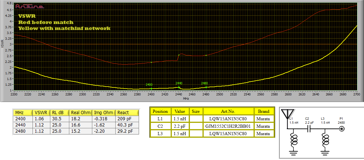
Measured original and final matched result. Notify table values such as resistance and reactance for low VSWR is far away from 50 Ohm.
Antenna efficiency is not shown, It was measured as a part of antenna shape design, previous done.
If you not have a VNA that is GPIB compatible will not this kind of software working as VNA extension be of much help.
VNA extending software, adds functionality which VNA not had before. Even old HP VNA will get auto port forwarding, FFT, a lot of memory and clear big color screen just to mention a few things.
This kind of software is useless as simulation tool. There exist a lot of better alternatives for doing RF simulations.
I mention this several times as it is a common mistake to think about this kind of software as a simulation tool.
It is a measurement tool, using real data delivered from an VNA in real time. For virtual network is real measured S-parameters used for each L and C component. Each virtual component is interchangeable with real components. Measured result or virtual result are interchangeable as non ideal circumstances are taken in account in every step.
Both radio and antenna impedance are measured values, anything else is not possible when doing serious matching job.


