Hello
just came across an interesting stuff. Was looking for a reference schematic how to terminate properly an RF IC with differential current outputs. The easiest way is of course using a proper RF transformer. While looking for some inspiration for part numbers and schematic concepts, I found
a few many of them... let's say interesting.
Looking at the datasheet, for example this one:
https://ww2.minicircuits.com/pdfs/TC1-1T+.pdf They do say the transformer ratio is 1:1. Does that mean that all three windings have the same number of turns (1:1:1) or does that mean the center tap is really a center tap, and the ratio is indeed 1:0.5:0.5? I think the latter should be right.
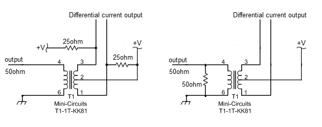
Now looking at some amateur implementations of such balun for the RF IC, I am becoming a little confused even though I should understand quite well how the balun works. See the example #1 here:

The T1-1T is obviously a 1:1 transformer, according to the datasheet. By using any of the two assumptions about the turn ratios above, the circuit just ain't right, or is it? Why is he transformer terminated both sides? Does not make sense.
Example #2. This seem not right either.

This is even more crazy. I found the TTWB4 transformer to be 1:4 ratio. So 16x gets the impedance transformed. Again, why is the transformer doubly terminated? Doesn't make sense to me. Don't you just need to terminate once, to convert the differential current outputs into single ended voltage out at 50ohm?
What I think should be enough is just use the 1:1 balun (1:0.5:0.5 like the T1-1T or TC1-1T+), terminate both leads from the RF IC with 25ohm and voila, have a 50ohm out?
OR use the same transformer, current drive the primary directly and then terminate single resistor 50ohm on the secondary? Should not this be enough?
Am I missing something or am completely dumb? As I could find a shitton of other schematics on the web, that has the balun implemented wrong, as far as I can tell. The only schematic I could find in a minute or two that seemed to be correct (using only two 25ohm resistors) was the manufacturer EVALuation board for that IC.


