Author Topic: Strange BFO issue: runs then stops  (Read 7185 times)

0 Members and 1 Guest are viewing this topic.

Offline ChristofferBTopic starter

  • Frequent Contributor
  • **
  • Posts: 929
  • Country: dk
  • Chemistry phd student!
    • My channel:
Strange BFO issue: runs then stops
« on: July 13, 2017, 02:45:16 pm »
Hi! I'm currently building a shortwave SSB receiver. The RF part works fine, so now I'm working on the 455KHz IF side of things.

Here's the 'block diagram'

->[IF filter]->[IF amp]->(prod. det.)->[AF AMP]
                                        î
                                    [BFO]

Receiver works pretty good for about a minute, then the BFO dies, output simply flatlines, and of course, nothing is received then.

I'm at a complete loss as to what could cause this. Has anyone experienced anything like it? Any common causes?

Attached is my schematic. The output frequency is a bit high, so I've tried to pull it a bit more than shown here. 20 nf across the variable cap or so.
Transistor's just a standard BC548

The bfo is fed directly to a product detector made from a 10-turn toroidal transformer and some diodes, the one shown here:
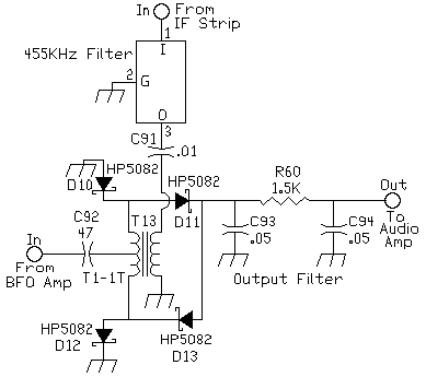

Any insight into the world of IF would be greatly appreciated!

thanks!
« Last Edit: July 13, 2017, 02:50:50 pm by ChristofferB »
--Christoffer //IG:Chromatogiraffery
Check out my scientific instruments diy (GC, HPLC, NMR, etc) Channel: https://www.youtube.com/channel/UCZ8l6SdZuRuoSdze1dIpzAQ
 

Offline ChristofferBTopic starter

  • Frequent Contributor
  • **
  • Posts: 929
  • Country: dk
  • Chemistry phd student!
    • My channel:
Re: Strange BFO issue: runs then stops
« Reply #1 on: July 13, 2017, 03:38:19 pm »
New discovery; there was a bad diode in the product detector. When the BFO. was connected to the prod.det. , it the output was down to around 0.8Vp-p, and with no load, its output closes 5Vp-p! - likely that the heavy load would heat up the transistor of the BFO and caused it to fail, but I don't know yet. Haven't figured out if one should have a BFO level potentiometer inbetween either.
--Christoffer //IG:Chromatogiraffery
Check out my scientific instruments diy (GC, HPLC, NMR, etc) Channel: https://www.youtube.com/channel/UCZ8l6SdZuRuoSdze1dIpzAQ
 

Offline BigBoss

  • Regular Contributor
  • *
  • Posts: 115
  • Country: fr
Re: Strange BFO issue: runs then stops
« Reply #2 on: July 13, 2017, 07:05:52 pm »
It might be a thermal drift or bad designed oscillator.
Critical oscillator bias circuitry must be designed so closed loop gain and phase should always maintain the Barkhausen oscillation conditions-at least ..
I recommend you to modify this oscillator circuit with a thermal compensated bias circuit and I guess it does not love to oscillate due to poorly designed circuit or poor crystal specifications.
Because even the diode is short circuit, oscillator shouldn't stop, its output level can drop but it runs as desired.I think the oscillator has also some sickness..
 
The following users thanked this post: ChristofferB

Offline PA0PBZ

  • Super Contributor
  • ***
  • Posts: 5125
  • Country: nl
Re: Strange BFO issue: runs then stops
« Reply #3 on: July 13, 2017, 07:25:44 pm »
20 nf across the variable cap or so.

If it still fails what happens when you replace that cap by a more sane value, let's say 100p?
I understand that the freq will be off but just as a test.
Keyboard error: Press F1 to continue.
 
The following users thanked this post: ChristofferB

Offline vk3yedotcom

  • Frequent Contributor
  • **
  • Posts: 612
  • Country: au
    • vk3ye dot com (radio articles and projects)
Re: Strange BFO issue: runs then stops
« Reply #4 on: July 13, 2017, 08:22:06 pm »
I would be looking at the relationship between the BFO and the product detector. Eg is the product detector loading down the BFO too much and causing oscillation to drop out?

A diode product detector typically has a fairly low impedance and requires a high level BFO. 

To generate the required BFO level and provide isolation between the BFO and product detector it's good design practice to insert a one transistor buffer amplifier.

An example is in the Bitx transceiver - circuit at http://www.phonestack.com/farhan/bitx.html
NEW! Ham Radio Get Started: Your success in amateur radio. One of 8 ebooks available on amateur radio topics. Details at  https://books.vk3ye.com
 
The following users thanked this post: ChristofferB

Offline ChristofferBTopic starter

  • Frequent Contributor
  • **
  • Posts: 929
  • Country: dk
  • Chemistry phd student!
    • My channel:
Re: Strange BFO issue: runs then stops
« Reply #5 on: July 13, 2017, 08:56:07 pm »
Thanks for the interest! I did manage to get it going, and I do get some reception, but as said, the BFO output is dragged fairly low, so it might be a sound investment to buffer it.

I'm not really certain what buffer topology would be best for an 455KHz, and I couldn't really find any examples with VCC=9V to plagiarize, so I think I'll just duplicate my IF amp stage and use that:

--Christoffer //IG:Chromatogiraffery
Check out my scientific instruments diy (GC, HPLC, NMR, etc) Channel: https://www.youtube.com/channel/UCZ8l6SdZuRuoSdze1dIpzAQ
 

Online T3sl4co1l

  • Super Contributor
  • ***
  • Posts: 21657
  • Country: us
  • Expert, Analog Electronics, PCB Layout, EMC
    • Seven Transistor Labs
Re: Strange BFO issue: runs then stops
« Reply #6 on: July 14, 2017, 12:04:03 am »
Your diagram shows schottky diodes.  One would expect them to heavily load any port supplied by > 0.5V peak.

Indeed, this is the trick with DBMs: the LO port should be overdriven, from a current limited source (normally a matched impedance, i.e. 50 ohms or the like), so that the pairs of diodes it drives into conduction are driven with a near square wave.  The pairs of conducting diodes then connect the two remaining ports together.  Since the LO is alternating, the phase of that connection alternates, thus achieving detection.

If this is shorting out your oscillator, it would seem the solution is as simple as adding a series resistor, or reducing the value of the coupling capacitor (so its reactance plays a similar role). :)

Tim
Seven Transistor Labs, LLC
Electronic design, from concept to prototype.
Bringing a project to life?  Send me a message!
 
The following users thanked this post: ChristofferB

Offline w2aew

  • Super Contributor
  • ***
  • Posts: 1780
  • Country: us
  • I usTa cuDnt speL enjinere, noW I aR wuN
    • My YouTube Channel
Re: Strange BFO issue: runs then stops
« Reply #7 on: July 14, 2017, 02:01:00 pm »
To better understand the mixer operation, you might enjoy these two videos of mine:


And...


YouTube channel: https://www.youtube.com/w2aew
FAE for Tektronix
Technical Coordinator for the ARRL Northern NJ Section
 
The following users thanked this post: ChristofferB

Offline G0HZU

  • Super Contributor
  • ***
  • Posts: 3015
  • Country: gb
Re: Strange BFO issue: runs then stops
« Reply #8 on: July 14, 2017, 02:48:05 pm »
Thanks for the interest! I did manage to get it going, and I do get some reception, but as said, the BFO output is dragged fairly low, so it might be a sound investment to buffer it.

I'm not really certain what buffer topology would be best for an 455KHz, and I couldn't really find any examples with VCC=9V to plagiarize, so I think I'll just duplicate my IF amp stage and use that:


You haven't given any resistor values in your circuit but that circuit will tend to have a 'very' low input (and output) impedance. Probably best to include a fairly large series resistor at the input to this circuit to stop it loading your oscillator circuit and also to get a sensible voltage level at the input/output. Ideally, it should have a series resistor at its output, typically 47R if you want to have a 50R output. This type of circuit can have very good reverse isolation. In your case you don't need lots of voltage gain, you just need a buffer that can deliver the right drive level to the BFO so you would have to design it for resistor values that keep the voltage levels sensible.
« Last Edit: July 14, 2017, 02:54:12 pm by G0HZU »
 
The following users thanked this post: ChristofferB

Offline ChristofferBTopic starter

  • Frequent Contributor
  • **
  • Posts: 929
  • Country: dk
  • Chemistry phd student!
    • My channel:
Re: Strange BFO issue: runs then stops
« Reply #9 on: July 14, 2017, 05:45:41 pm »
Thanks for the replies! I forgot to mention that the mixer's made with standard 1n4148's!

Putting a resistor in series with the amp may be a good idea! What is 'fairly large'?
in the amp: R9,R10,R11 are 1K, 5,6K, 470ohm and R12 is 1K

W2AEW: I'm pretty convinced I have watched them in the past, they're great nevertheless!
--Christoffer //IG:Chromatogiraffery
Check out my scientific instruments diy (GC, HPLC, NMR, etc) Channel: https://www.youtube.com/channel/UCZ8l6SdZuRuoSdze1dIpzAQ
 

Online T3sl4co1l

  • Super Contributor
  • ***
  • Posts: 21657
  • Country: us
  • Expert, Analog Electronics, PCB Layout, EMC
    • Seven Transistor Labs
Re: Strange BFO issue: runs then stops
« Reply #10 on: July 14, 2017, 09:29:46 pm »
Hmmm, a resistor around 1k, or a capacitor around 350pF.  Try different values.  Can also rewind the transformer so it steps down, so you get a low impedance at the diodes and a higher impedance at the LO.  Or, to put it another way: you've already found you're not going to get the full 5V from the LO, so you have to burn some of it in an impedance, and maybe step it down to the ~1.2V at the diodes, too.

Tim
Seven Transistor Labs, LLC
Electronic design, from concept to prototype.
Bringing a project to life?  Send me a message!
 

Offline G0HZU

  • Super Contributor
  • ***
  • Posts: 3015
  • Country: gb
Re: Strange BFO issue: runs then stops
« Reply #11 on: July 14, 2017, 11:19:05 pm »
Your buffer amp will have a very low input impedance for small signals (maybe less than 50 ohms?) and lots of voltage gain so you need a fairly large series resistor at the input to define the input impedance (presented to the oscillator output) and this resistor will also help control the voltage gain from input to output to a sensible amount.

I would start off with 4700R in series at the buffer input and see if you get enough LO drive to the diodes. The amp will then produce a (small signal) voltage gain of about 5600/4700 and the input impedance will be about 4700 ohm. So it won't load your crystal oscillator very much.

Your BFO circuit is drawn in a strange way because I would normally feed the LO to the single winding and feed the IF to the centre tap. i.e. swap the ports around. This way you get the diodes driven in antiphase and you get LO cancellation at the output. Also, you need to define/control the DC operating point at the output of the BFO or the circuit can misbehave especially if you feed it to an AF stage with DC bias on it.
« Last Edit: July 14, 2017, 11:52:01 pm by G0HZU »
 

Offline ChristofferBTopic starter

  • Frequent Contributor
  • **
  • Posts: 929
  • Country: dk
  • Chemistry phd student!
    • My channel:
Re: Strange BFO issue: runs then stops
« Reply #12 on: July 14, 2017, 11:49:39 pm »
Maybe I should try swapping the product detector ports then!

I've tried installing 1K as buffer input limiting, and 50ohm as output impedance matching, and with this configuration I get around 0.8V at the BFO side of the amp and 0.1V at the product detector port.. Should I simply go for another, more high impedance buffer, or ?

By the way, my series decoupling capacitors are 100nF, just chosen out of habit.. could that be an issue?

thanks again!
--Christoffer //IG:Chromatogiraffery
Check out my scientific instruments diy (GC, HPLC, NMR, etc) Channel: https://www.youtube.com/channel/UCZ8l6SdZuRuoSdze1dIpzAQ
 

Offline G0HZU

  • Super Contributor
  • ***
  • Posts: 3015
  • Country: gb
Re: Strange BFO issue: runs then stops
« Reply #13 on: July 15, 2017, 12:27:04 am »
No don't swap the BFO ports around because the transformer may be wound with turns ratios to impedance match each port correctly. I'm just not used to seeing the circuit drawn the way you have drawn it so this has thrown me a bit.

I really just wanted to advise you about your buffer amplifier. It will have a very low input impedance so you need to be aware of this.
« Last Edit: July 15, 2017, 12:31:09 am by G0HZU »
 

Offline ChristofferBTopic starter

  • Frequent Contributor
  • **
  • Posts: 929
  • Country: dk
  • Chemistry phd student!
    • My channel:
Re: Strange BFO issue: runs then stops
« Reply #14 on: July 15, 2017, 01:03:56 am »
Sorry, slow perception at 3AM. I think next step is to ditch the amp I inserted and design a standard higher impedance single transistor buffer. If that won't bring the BFO way up I may re-do the product detector with a dual-gate J-fet or something similar, requiring less violent LO.
--Christoffer //IG:Chromatogiraffery
Check out my scientific instruments diy (GC, HPLC, NMR, etc) Channel: https://www.youtube.com/channel/UCZ8l6SdZuRuoSdze1dIpzAQ
 

Offline G0HZU

  • Super Contributor
  • ***
  • Posts: 3015
  • Country: gb
Re: Strange BFO issue: runs then stops
« Reply #15 on: July 15, 2017, 01:07:16 am »
Quote
I've tried installing 1K as buffer input limiting, and 50ohm as output impedance matching, and with this configuration I get around 0.8V at the BFO side of the amp and 0.1V at the product detector port.. Should I simply go for another, more high impedance buffer, or ?

I don't want to get too caught up in this stuff as I don't have much free time at the moment but I can give you a few (crude) pointers as to how to 'tinker' with your buffer circuit. Providing you stick with sensible resistor values you can think of it in these terms:

Looking at the amended circuit diagram below:

Assuming C3 is large enough to be insignificant...

Input impedance = R1 (this is because the input impedance at the transistor base is very low, maybe <50 ohms)

Voltage gain Vin to Vout = R10/R1    (This is only approximate and only applies to small signals and won't apply if the amp starts to clip)

The voltage at Q3 collector ideally needs to be just above Vcc/2 which is about 5V. So to maintain this then R10/R9 needs to be kept at about a ratio of approx. 5.5:1.

So if you change R10 to change the AC voltage gain then you need to change R9 as well. Otherwise the amplifier will not have the right DC voltage at Q3 collector.

Note that all of the above is just an approximation and don't expect it to behave exactly like this. But hopefully this will help you understand your buffer circuit better :)

« Last Edit: July 15, 2017, 10:36:06 am by G0HZU »
 
The following users thanked this post: ChristofferB

Online T3sl4co1l

  • Super Contributor
  • ***
  • Posts: 21657
  • Country: us
  • Expert, Analog Electronics, PCB Layout, EMC
    • Seven Transistor Labs
Re: Strange BFO issue: runs then stops
« Reply #16 on: July 15, 2017, 01:37:39 am »
Just an emitter follower will get you plenty of current gain and isolation to keep the IF and LO happy.

Tim
Seven Transistor Labs, LLC
Electronic design, from concept to prototype.
Bringing a project to life?  Send me a message!
 

Offline ChristofferBTopic starter

  • Frequent Contributor
  • **
  • Posts: 929
  • Country: dk
  • Chemistry phd student!
    • My channel:
Re: Strange BFO issue: runs then stops
« Reply #17 on: July 16, 2017, 08:11:38 pm »
Thanks all for your assistance! I have one more question though:

I've rebuilt the buffer as a simple voltage follower, as seen in schematic below. Afterwards, the BFO gives a good full swing, but the output is still very low - around 0.8V - this time with a very funky waveform! What has happened, and what could be optimized??
--Christoffer //IG:Chromatogiraffery
Check out my scientific instruments diy (GC, HPLC, NMR, etc) Channel: https://www.youtube.com/channel/UCZ8l6SdZuRuoSdze1dIpzAQ
 

Offline ahbushnell

  • Frequent Contributor
  • **
  • Posts: 738
  • Country: us
Re: Strange BFO issue: runs then stops
« Reply #18 on: July 16, 2017, 09:55:25 pm »
Don't you need bias on your amp so the signal can swing both ways?   
 

Online T3sl4co1l

  • Super Contributor
  • ***
  • Posts: 21657
  • Country: us
  • Expert, Analog Electronics, PCB Layout, EMC
    • Seven Transistor Labs
Re: Strange BFO issue: runs then stops
« Reply #19 on: July 17, 2017, 01:21:47 am »
Yeah, remove the input coupling capacitor, so it gets biased by the BFO collector voltage.  Also, split the BFO's collector resistor into two 1k's in series, and use that "tap" to supply the follower.

Tim
Seven Transistor Labs, LLC
Electronic design, from concept to prototype.
Bringing a project to life?  Send me a message!
 

Offline ChristofferBTopic starter

  • Frequent Contributor
  • **
  • Posts: 929
  • Country: dk
  • Chemistry phd student!
    • My channel:
Re: Strange BFO issue: runs then stops
« Reply #20 on: July 17, 2017, 02:00:10 am »
That sounds like a sound plan. I'll implement that tomorrow.

 I've drawn up the design as it looks so far:
--Christoffer //IG:Chromatogiraffery
Check out my scientific instruments diy (GC, HPLC, NMR, etc) Channel: https://www.youtube.com/channel/UCZ8l6SdZuRuoSdze1dIpzAQ
 

Online T3sl4co1l

  • Super Contributor
  • ***
  • Posts: 21657
  • Country: us
  • Expert, Analog Electronics, PCB Layout, EMC
    • Seven Transistor Labs
Re: Strange BFO issue: runs then stops
« Reply #21 on: July 17, 2017, 02:23:05 am »
Eh, don't forget the junction dot for the base bias divider. :o

Tim
Seven Transistor Labs, LLC
Electronic design, from concept to prototype.
Bringing a project to life?  Send me a message!
 

Offline ChristofferBTopic starter

  • Frequent Contributor
  • **
  • Posts: 929
  • Country: dk
  • Chemistry phd student!
    • My channel:
Re: Strange BFO issue: runs then stops
« Reply #22 on: July 17, 2017, 02:26:35 am »
I haven't! it's there in the schematic file, dunno why it doesn't show on exported bitmap.
--Christoffer //IG:Chromatogiraffery
Check out my scientific instruments diy (GC, HPLC, NMR, etc) Channel: https://www.youtube.com/channel/UCZ8l6SdZuRuoSdze1dIpzAQ
 

Offline ChristofferBTopic starter

  • Frequent Contributor
  • **
  • Posts: 929
  • Country: dk
  • Chemistry phd student!
    • My channel:
Re: Strange BFO issue: runs then stops
« Reply #23 on: July 17, 2017, 09:16:52 pm »
I implemented aforementioned circuit, and it gives a very cleanly shaped wave at the output! Only at 1.2VP-P, and it still loads down the BFO quite a bit.. down to around 3Vp-p.
Still, having a clean output at 1V peak is probably easier to work with than a 2V peak signal that's not very pretty.

thanks!
--Christoffer //IG:Chromatogiraffery
Check out my scientific instruments diy (GC, HPLC, NMR, etc) Channel: https://www.youtube.com/channel/UCZ8l6SdZuRuoSdze1dIpzAQ
 

Online T3sl4co1l

  • Super Contributor
  • ***
  • Posts: 21657
  • Country: us
  • Expert, Analog Electronics, PCB Layout, EMC
    • Seven Transistor Labs
Re: Strange BFO issue: runs then stops
« Reply #24 on: July 18, 2017, 12:25:52 pm »
It should load down; if it's not, you aren't delivering any power!  Sounds pretty reasonable then. :)

Tim
Seven Transistor Labs, LLC
Electronic design, from concept to prototype.
Bringing a project to life?  Send me a message!


Share me

Digg  Facebook  SlashDot  Delicious  Technorati  Twitter  Google  Yahoo
Smf