i think alot of literature on RF is garbage if you don't have a ridiculous mathematical background.
I have experience with MV calculus, differential equations, physics, linear algebra and half of this stuff would require me to get textbooks I never seen before to attempt. I know where to look if I really wanted to figure some solutions out but its just not appealing to do so at all for fun/hobby. There is also a TON of untested theoretical stuff out there because no one can afford to buy the mathematician machine shop hours to test his work. Look for documents prior to like 1975 if you want to get the intuitive feel you are looking for. Otherwise you are going to get literally clobbered with math. The military is particularly useful at explaining antennas if you can find their researchers documents from navy lab etc.
Some of the stuff I picked up at a university library that was more recent is like being stupid enough to open the mall doors in a zombie invasion. Just compare something like sedra smith to the art of electronics, with RF/plasma its much worse.
The absolute worse shit (only rivaled by SOME books about DSP) is this tome I found about radars once. Oh man cool satellite dish on the cover, some stars, I thought 'damn they musta built some kind of cool radio astronomy van', I thought I would be dog earing that thing in a cafe.. I open it and I feel my eyes diverting and eventually bulging out of my head. Pages upon pages of surface integrals. Not a single picture of anything useful or practical, I could not even find a fucking sketch of something remotely useful. If it was called "boring ass addendum used to optimize cost sensitive radar designs that is useful between the years 1985-1988 and may summon evil spirits" I would have given it some credit. Instead it was called something like 'introduction to radars". To this way I wonder what the person looked like that would find it to be a introduction to radars. I know what they probably looked like, the greeks described this creature as a "gorgon".
What you get in a old textbook, is less math nonsense optimization, and some examples of earlier experiments that help clarify. You just won't understand the process unless you got an idea of how they started developing that math. No engineer approached it from a rigid theoretical framework, they found one that fit eventually when they got some kind of peicewise model going (which is still useful to know).
***
Actually I will say, there is one beast that may be worse then the microwave books, this is the nuclear physics books. I found some shit written in German before (probably pulled out of the fuhers eagle castle) that blitzkreiged my fucking brain. The only interesting thing about it was that I learned they had a integral symbol on a special type writer. I was told there was only a few copies of those books in existence( for good reason). Yea thats right, I am pretty sure it was Nazi literature about reactors. Something like 1936. Despite being horrific on the eyes, there is the possibility the book was called something like "how to perform detailed calculation of nuclear subsystem xx5" (well known German specificity) rather then 'introduction to nuclear energy'. Double surface integral

or something on the first freaking page. Believe it musta been un-touched for at least 50 years given how difficult it was to pry out of the book shelf and how glued it was to surrounded literature. It smelled bad and I always wondered what would happen if you approached it with a Geiger counter.
**************************************************************************
And to answer the OP question, what it looks like is the antenna is in the middle and there is a stationary sensor and the antenna rotates around at a fixed distance. The antenna wont orbit the sensor because thats too complicated to make a track its easier to put it on a swivel joint and spin it around. Like no one would do that because its a ridiculous amount of variables to add
they use this type of stuff
https://www.pasternack.com/rf-rotary-joints-category.aspxthen the planes should be easy to imagine once you get the image of the setup
You don't want to move the cables around because they introduce flex-related phase error and they wear down (being made of foam dielectric typically for better cables), wheras the rotary joint comes with a manufacturers specification and it can be easily replaced.
The EMI labs and even small room test stations with a single wall all come with a kind of turn table that has a controller which you can make it spin, and it has a signal that outputs the angle and you control its speed, they often put a wooden table on top of it.
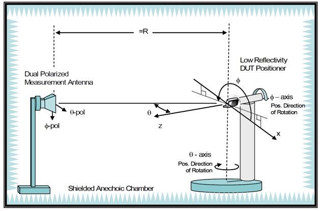
so you make a polar plot based on the angle the table sensor puts out and the signal (often just power) from the receiver antenna. You can go 3d polar if you add another rotary joint or some kind of universal joint and have it sweep.
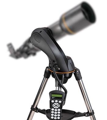
I made something like this out of a old hobby telescope mount, it spins in a circle and up and down a certain number of degrees and you program it with a little controller and it runs on 12V. Decent construction quality etc. Has a camera screw on the bottom to mount to a decent tripod and the base is fly-cut aluminum for flatness.
If you are testing antenna polarity you also want to be able to tilt the antenna on another axis. You can also use a actuator to move the height of the antenna around if you get it high up in the air (think like a basketball hoop) rather then try to tilt it.
you can add another rotary platform to rotate the antenna but then you need more joints, and it might be cheaper, easier and more stable to make the receiver rotate rather then giving the antenna a rotational axis along its major axis (where it radiates the most energy if its directional, like the face of a horn).
Those 3d plots are mostly the same shit as the projects that you see about turning a hand-held IR laser thermometer into a REALLY SLOW thermal imaging camera, but keep the phase in mind (meaning you need to rotate it 360 degrees at all measurement points).
https://hackaday.com/2011/03/09/arduino-thermo-cam/but instead of reflection back into the transmitter, imagine the laser as a flashlight that moves around at every possible angle relative to the sensor and backfeeds its position.
The confusing part might be the receiver, but keep in mind it has its own profile (you can imagine it for simplicity as a camera lens with a specific FOV), and you measure that FOV constantly, you are not measuring a single point. If you have a 15 degree FOV on the sensor (say the horn angle), and you rotate the antenna being measured by 1 degree, you are still measuring 15 degrees, so you can kinda think of a box-car filter like effect going on. You just get a magnitude.
More advanced systems might measure it with a phased array or something, but its unlikely you will ever see this unless they are testing it with a AEGIS missile cruiser or F22 radar (supposedly). Everyone else just rotates shit mechanically.