Author Topic: > 1 GHz DIY differential probes  (Read 66112 times)

huyphuc92 and 1 Guest are viewing this topic.

Online dietert1

  • Super Contributor
  • ***
  • Posts: 2061
  • Country: br
    • CADT Homepage
Re: > 1 GHz DIY differential probes
« Reply #75 on: October 22, 2018, 06:57:17 pm »
Yes, definitely 10x gain is  better than 5x. Also very interesting: The THS4303 datasheet contains a schematic diagram of the amplifier.
When we compare the large signal gain curves (Figure 3), both amplifiers show the -3 dB point at about 1.4 or 1.5 GHz. The THS3402 has a minor bandwidth advantage only with small signals.
My own 1.8 GHz bandwidth estimate above was "almost large signal": -10 dBm into 50 Ohm = 200 mVpp, 5x => 1 Vpp.
 

Offline David Hess

  • Super Contributor
  • ***
  • Posts: 16607
  • Country: us
  • DavidH
Re: > 1 GHz DIY differential probes
« Reply #76 on: October 24, 2018, 09:08:57 pm »
Both designs are well and good in themselves, but don't forget that the title contains >1GHz and differential in its title.

Both are single ended, the JFETs in Bob's design run out of steam at ~200MHz and the P6202 is a 500MHz design.

I linked them as examples of what is involved.  Both serve as benchmarks for what is possible without resorting to hybrid construction.

I think a >1GHz differential probe is unrealistic without hybrid construction but performance better than the famous and very long lived Tektronix 100MHz P6046 differential probe should be feasible.  I would take a very close look at maximum performance design using the AD8130 difference amplifier as the differential to single ended conversion stage to get better than P6046 performance.

If there is a better part than the AD8130 for differential probes, I have not found it yet.
 

Online dietert1

  • Super Contributor
  • ***
  • Posts: 2061
  • Country: br
    • CADT Homepage
Re: > 1 GHz DIY differential probes
« Reply #77 on: October 25, 2018, 07:25:45 am »
The amplifier testkits i wrote about are no hybrids but standard PC boards. The LMH3401 board has four layers with the amplifier side made from RF material. Its common mode is near perfect up to 3 GHz, its differential mode extends up to 7 GHz (datasheet spec). The HEMT fet buffer i tested should be good for 5 or 10 GHz as well. The wiggles in my measurements are reflections and mean nothing. Some days ago i found better patch cables and some SMA attenuators which make the measurements smooth to about +/- 0.2 dB.
If you prefer AD over TI, the differential amplifier ADL5565 mentioned above seems to be very similar to the LMH3401. Or the ADL5569 with 2x 20 dB gain on a single chip and good common mode suppression up to 3 GHz.
If you want to make hybrids, please search for "agilent ghz die" at ebay. Wellcome to 2018!
« Last Edit: October 25, 2018, 09:03:58 am by dietert1 »
 

Offline Marco

  • Super Contributor
  • ***
  • Posts: 6719
  • Country: nl
Re: > 1 GHz DIY differential probes
« Reply #78 on: October 25, 2018, 02:42:42 pm »
AFAICS it's impossible to guess what the CMRR is for the ADs for single ended output. Only the LMH3401 has anything in the datasheet about it (Fig. 42, Common-mode input, common-mode output transfer function).
 

Online nctnico

  • Super Contributor
  • ***
  • Posts: 26895
  • Country: nl
    • NCT Developments
Re: > 1 GHz DIY differential probes
« Reply #79 on: October 25, 2018, 04:42:56 pm »
Both designs are well and good in themselves, but don't forget that the title contains >1GHz and differential in its title.

Both are single ended, the JFETs in Bob's design run out of steam at ~200MHz and the P6202 is a 500MHz design.

I linked them as examples of what is involved.  Both serve as benchmarks for what is possible without resorting to hybrid construction.

I think a >1GHz differential probe is unrealistic without hybrid construction but performance better than the famous and very long lived Tektronix 100MHz P6046 differential probe should be feasible.  I would take a very close look at maximum performance design using the AD8130 difference amplifier as the differential to single ended conversion stage to get better than P6046 performance.

If there is a better part than the AD8130 for differential probes, I have not found it yet.
One way to get in the ball park of 1GHz is to use 2 closed loop buffers (from TI for example) and drive a regular opamp or differential amplifier with these to get the differential signal. It should be possible to get over 20k Ohm of differential input impedance and more if you make it a 1:10 probe but I think the capacitive divider will be tricky to get right.
There are small lies, big lies and then there is what is on the screen of your oscilloscope.
 

Online dietert1

  • Super Contributor
  • ***
  • Posts: 2061
  • Country: br
    • CADT Homepage
Re: > 1 GHz DIY differential probes
« Reply #80 on: October 26, 2018, 09:38:20 am »
If we are still considering DIY, a 3 mm "antenna" of thin wire soldered vertical to one end of a 0603 resistor helps. Then you can adjust compensation by bending the loose end in one direction or the other. Also "solder blobs" were mentioned above.
 

Online nctnico

  • Super Contributor
  • ***
  • Posts: 26895
  • Country: nl
    • NCT Developments
Re: > 1 GHz DIY differential probes
« Reply #81 on: October 26, 2018, 11:55:11 am »
The question is how low do you want to get the input capacitance. On one of my prototypes I measured less than 0.5pf between the tips (and that is with some uncertainties). The actual capacitance between the tips may even be lower. This also implies that aiming for a very high differential input impedance isn't going to do much good because at several GHz the input capacitance will dominate the input impedance anyway.
There are small lies, big lies and then there is what is on the screen of your oscilloscope.
 

Offline 0xdeadbeef

  • Super Contributor
  • ***
  • Posts: 1572
  • Country: de
Re: > 1 GHz DIY differential probes
« Reply #82 on: October 26, 2018, 06:26:03 pm »
This also implies that aiming for a very high differential input impedance isn't going to do much good because at several GHz the input capacitance will dominate the input impedance anyway.
While it's true of course that a capacitance becomes low ohmic at high frequencies (e.g. 1pF at 1GHz equals ~159Ohm), your signal typically consists of a wide range of frequencies where the (real part) resistance will matter the more, the more low frequency components you have.
Trying is the first step towards failure - Homer J. Simpson
 

Online dietert1

  • Super Contributor
  • ***
  • Posts: 2061
  • Country: br
    • CADT Homepage
Re: > 1 GHz DIY differential probes
« Reply #83 on: October 26, 2018, 10:28:18 pm »
This will be similar to any other scope frontend.  Once you know how to DIY you can solve the DC impedance problem using AC coupling or using an adjustable DC offset source or by adapting the division ratio. Depends on the application.
For myself i want a high impedance 10:1 probe, so i designed a small 4-layer board with 2x HEMT buffers plus DC servos plus a LMH3401 difference stage plus low noise +/- 2.5 V regulators. A HEMT easily oscillates above 10 GHz and the probe will have two of them next to each other, so i already know i will suffer. Probably i should first try a THS4303 single ended 10:1 probe, will be much easier.
 

Offline Marco

  • Super Contributor
  • ***
  • Posts: 6719
  • Country: nl
Re: > 1 GHz DIY differential probes
« Reply #84 on: October 27, 2018, 12:13:26 am »
The quality to which Baluns can be made is quite impressive by the way. Marki has one which does 40 dB CMRR out to 6 GHz ... they of course go higher, but for those the CMRR is reduced across the board.

What's inside these things? I suspect ferrite on coax.
 

Offline Marco

  • Super Contributor
  • ***
  • Posts: 6719
  • Country: nl
Re: > 1 GHz DIY differential probes
« Reply #85 on: October 29, 2018, 12:58:06 pm »
Discontinued.
Such a shame too. Some of those Broadcomm pHEMT's go up to a transconductance of 2000 mS, there's nothing else like them in the discrete world.
 

Online nctnico

  • Super Contributor
  • ***
  • Posts: 26895
  • Country: nl
    • NCT Developments
Re: > 1 GHz DIY differential probes
« Reply #86 on: October 29, 2018, 02:14:55 pm »
Discontinued.
Such a shame too. Some of those Broadcomm pHEMT's go up to a transconductance of 2000 mS, there's nothing else like them in the discrete world.
Off topic: IMHO it is a major PITA that Broadcom is killing all the nice RF parts from HP/Agilent/Avago. Also a lot of opto stuff is being discontinued.  :wtf:
There are small lies, big lies and then there is what is on the screen of your oscilloscope.
 

Offline LapTop006

  • Supporter
  • ****
  • Posts: 467
  • Country: au
Re: > 1 GHz DIY differential probes
« Reply #87 on: October 29, 2018, 02:53:08 pm »
Off topic: IMHO it is a major PITA that Broadcom is killing all the nice RF parts from HP/Agilent/Avago. Also a lot of opto stuff is being discontinued.  :wtf:

Given how hard it is to be able to purchase or even just get real datasheets for their parts that might actually be the better option, at least now a competitor knows they have a good chance at picking up customers.
 

Offline Marco

  • Super Contributor
  • ***
  • Posts: 6719
  • Country: nl
Re: > 1 GHz DIY differential probes
« Reply #88 on: October 29, 2018, 04:31:02 pm »
High GHz discrete RF is such a niche that probably no one will pick them up. CEL and Skyworks will probably keep producing their parts for a while, but those just don't compare to Broadcomm's as far as transconductance is concerned. I don't see them developing ones to rival Broadcomm's ... gone with the wind now.
« Last Edit: October 29, 2018, 08:07:05 pm by Marco »
 

Online nctnico

  • Super Contributor
  • ***
  • Posts: 26895
  • Country: nl
    • NCT Developments
Re: > 1 GHz DIY differential probes
« Reply #89 on: October 31, 2018, 09:32:13 pm »
Today I had some time to put a new board with the LMH3401 together. The differential impedance is 2k Ohm with a 1:20 attenuation. I'm contemplating having a 1:50 version with 5k Ohm differential input impedance but that is for later. Some initial testing shows promising results:


This is with the input normal and reversed so it should give an idea on how good the common mode amplification is. I'll need to do a whole lot more testing but for that I need to finish the rest of the board first. This is just the amplifier (and 0402 decoupling capacitors) powered from a bench PSU.
« Last Edit: October 31, 2018, 09:35:45 pm by nctnico »
There are small lies, big lies and then there is what is on the screen of your oscilloscope.
 

Offline David Hess

  • Super Contributor
  • ***
  • Posts: 16607
  • Country: us
  • DavidH
Re: > 1 GHz DIY differential probes
« Reply #90 on: November 01, 2018, 12:08:25 am »
High GHz discrete RF is such a niche that probably no one will pick them up. CEL and Skyworks will probably keep producing their parts for a while, but those just don't compare to Broadcomm's as far as transconductance is concerned. I don't see them developing ones to rival Broadcomm's ... gone with the wind now.

NXP has discontinued their 4GHz PNP RF transistors as well and unlike some of the Avago/Broadcom parts, there are no substitutes for them or at least I have not found any.


Offline Gerhard_dk4xp

  • Frequent Contributor
  • **
  • Posts: 327
  • Country: de
Re: > 1 GHz DIY differential probes
« Reply #91 on: November 01, 2018, 12:57:59 am »
https://www.digikey.de/products/de?keywords=hfa3096bz-nd   >

but yes, it's a dying species.

regards, Gerhard
 

Offline Marco

  • Super Contributor
  • ***
  • Posts: 6719
  • Country: nl
Re: > 1 GHz DIY differential probes
« Reply #92 on: November 01, 2018, 01:12:50 am »
There are so many legacy BFT92 designs, they could charge 2$ a piece and they'd still sell them.
 

Online nctnico

  • Super Contributor
  • ***
  • Posts: 26895
  • Country: nl
    • NCT Developments
Re: > 1 GHz DIY differential probes
« Reply #93 on: November 15, 2018, 11:58:49 pm »
Time for an update on my design using an LMH3401. The differential impedance is 2k Ohm and the capacitance is less than 0.5pf (I can't measure any lower). The maximum differential input voltage is +/-20V RMS (based on dissipation). The maximum common-mode voltage is +/-13V. These ranges are wide enough to measure low-side current sense resistors and the gates of MOSFETs in the low side of a switching power supply as well.

First some graphs from the spectrum analyser up to 3GHz.
Normal and reverse connected bandwidth to show where the common mode amplification starts to deteriorate:


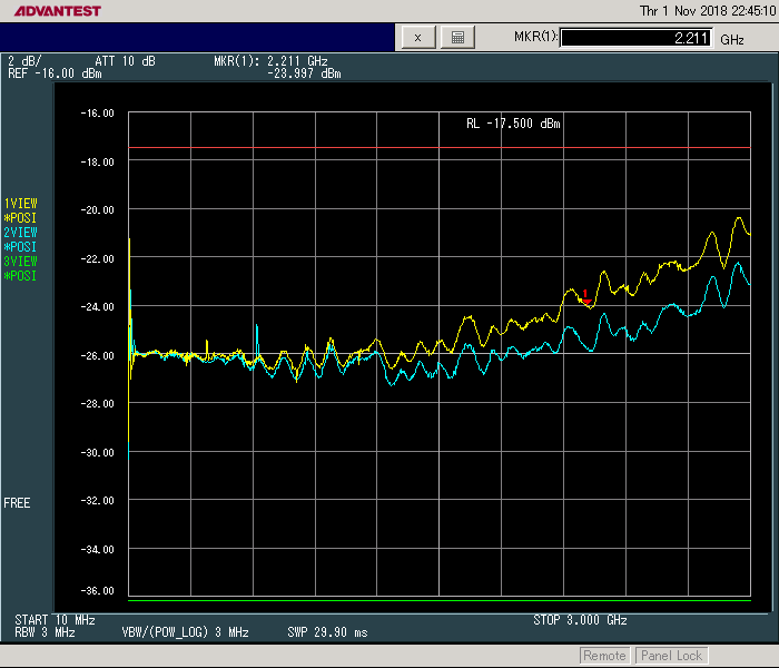
Common mode rejection:


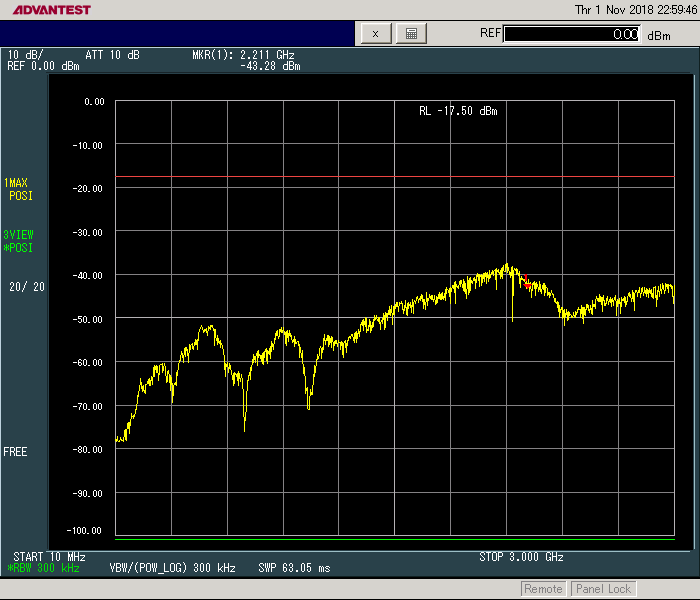
It looks reasonably flat up to 2.2GHz and the CMMR is -40dB at the worst point. All measurements where made using a levelled RF generator set to 0dBm and 50cm of Huber+Suhner coax (and a DC blocker) connected between the probe and the spectrum analyser.

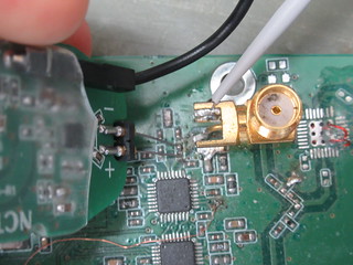
On to the practical part. On the differential probes I've seen there are moveably probe tips so points with a variety of distances can be probeb. I wanted to achieve something similar. After some thinking I came up with the idea of using thin stainless spring steel rods inserted into sockets. The end result is this:


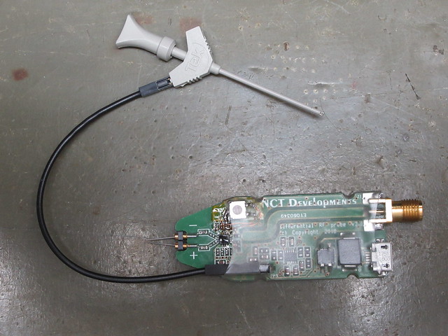
I didn't expect the offset voltage to be as bad as it is (in the prototype it is 30mV) so I had to bodge a potmeter onto it. The ground lead is to equalise the ground of the probe with the ground of the DUT. The power is supplied using a micro-USB connector. A switching capacitor chip with linear post-regulators provides a positive and negative suply voltage.

Let's measure some signals. First a 1.25Gbit ethernet stream:


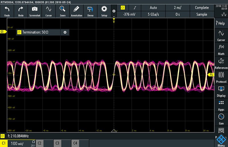
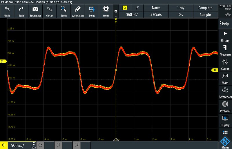
Secondly a 250MHz square wave:


The stainless steel spring rods seem to work fine. Probing a 0402 component is doable as well:


All in all I'm quite impressed. It took 3 board spins to come up with something decent. The results from the initial version with the ADA4927 made me sceptical about using a fully differential amplifier but I'm happy dietert1 held a strong argument in favour of using the LM3401.

I still need to add the potmeter to the final PCB design. Perhaps I'll add a slit between the input divider resistors to reduce the input capacitance as far as possible. If there is some interest I could have a small batch made. For now I have used heat-shrink tubing as a casing but I have created some indents in the board so it can be held in place in a 3D printed housing.
« Last Edit: November 16, 2018, 12:47:03 am by nctnico »
There are small lies, big lies and then there is what is on the screen of your oscilloscope.
 
The following users thanked this post: thm_w, Carrington, KE5FX, Manx, www.MKRD.info

Offline Hydron

  • Frequent Contributor
  • **
  • Posts: 985
  • Country: gb
Re: > 1 GHz DIY differential probes
« Reply #94 on: November 16, 2018, 11:41:36 am »
Looks great, definitely interested in more details/design info.

RE the offset issue - I assume that you're terminating the inverting output in 100R, could you potentially use this output to sense the offset when inputs are shorted and use a micro to calibrate it out using a digital pot/dac when a button is pressed? If the offset doesn't drift then this is probably overkill and a pot is the best.
 
The following users thanked this post: the Willows

Offline Carrington

  • Super Contributor
  • ***
  • Posts: 1202
  • Country: es
Re: > 1 GHz DIY differential probes
« Reply #95 on: November 16, 2018, 12:21:14 pm »
Cool!  :-+

... If there is some interest I could have a small batch made ...

I'm interested, and I think I'm not going to be the only one.  :)
My English can be pretty bad, so suggestions are welcome. ;)
Space Weather.
Lightning & Thunderstorms in Real Time.
 

Online nctnico

  • Super Contributor
  • ***
  • Posts: 26895
  • Country: nl
    • NCT Developments
Re: > 1 GHz DIY differential probes
« Reply #96 on: November 16, 2018, 03:11:17 pm »
Looks great, definitely interested in more details/design info.

RE the offset issue - I assume that you're terminating the inverting output in 100R, could you potentially use this output to sense the offset when inputs are shorted and use a micro to calibrate it out using a digital pot/dac when a button is pressed? If the offset doesn't drift then this is probably overkill and a pot is the best.
That could be an option. The datasheet from TI actually suggests to use an extra opamp to correct the offset error of the LMH3401. I'm wary to do that because it complicates the PCB design and some extra load needs to be connected to the output of the LMH3401. I suppose the offset doesn't drift that much but it is something I could test to see if it depends a lot on the operating temperature.
There are small lies, big lies and then there is what is on the screen of your oscilloscope.
 

Offline JohnGTopic starter

  • Frequent Contributor
  • **
  • Posts: 570
  • Country: us
Re: > 1 GHz DIY differential probes
« Reply #97 on: November 19, 2018, 02:34:27 pm »
Cool!  :-+

... If there is some interest I could have a small batch made ...

I'm interested, and I think I'm not going to be the only one.  :)

I would also be interested.

Thanks,
John
"Reality is that which, when you quit believing in it, doesn't go away." Philip K. Dick (RIP).
 

Offline dpenev

  • Regular Contributor
  • *
  • Posts: 188
Re: > 1 GHz DIY differential probes
« Reply #98 on: November 19, 2018, 04:18:34 pm »
I am interested too.

Sent from my MI NOTE Pro using Tapatalk


Offline rx8pilot

  • Super Contributor
  • ***
  • Posts: 3634
  • Country: us
  • If you want more money, be more valuable.
Re: > 1 GHz DIY differential probes
« Reply #99 on: November 19, 2018, 05:16:42 pm »
This is a very interesting and practical project. Very impressive results.

Digging through the rest of the thread looking to see how you measured impedance and capacitance - delicate measurements.

Short and misplld from my mobile......

Factory400 - the worlds smallest factory. https://www.youtube.com/c/Factory400


Share me

Digg  Facebook  SlashDot  Delicious  Technorati  Twitter  Google  Yahoo
Smf