Author Topic: > 1 GHz DIY differential probes  (Read 66107 times)

0 Members and 2 Guests are viewing this topic.

Offline joeqsmith

  • Super Contributor
  • ***
  • Posts: 11709
  • Country: us
Re: > 1 GHz DIY differential probes
« Reply #25 on: August 19, 2016, 03:19:41 am »
I don't want to break Elektor's copyright, but this is the specs:

Technical specification
• Attenuation: 10:1 with a differential signal and 50 ? termination in the ‘scope
• Differential input resistance: 5 k?
• Single-ended input resistance: 2.5 k?
• Output resistance: 50 ?
• Bandwidth: 1.9 GHz (–3 dB)
• Rise/fall time: 300 ps
• Power supply: ±8 to 12 V DC.

They also write:

For readers who are interested the author
offers ready-to-use and tested PCB modules, also a kit consisting of case, RF cable
with BNC connector and power supply
lead with plug. Further information from:
alfred_rosenkraenzer@gmx.de.

Looked to see if they had a website or something with more info.  Do you have a link besides the email address?

Offline Cerebus

  • Super Contributor
  • ***
  • Posts: 10576
  • Country: gb
Re: > 1 GHz DIY differential probes
« Reply #26 on: August 19, 2016, 12:48:57 pm »
I don't want to break Elektor's copyright, but this is the specs:

Technical specification
• Attenuation: 10:1 with a differential signal and 50 ? termination in the ‘scope
• Differential input resistance: 5 k?
• Single-ended input resistance: 2.5 k?
• Output resistance: 50 ?
• Bandwidth: 1.9 GHz (–3 dB)
• Rise/fall time: 300 ps
• Power supply: ±8 to 12 V DC.

They also write:

For readers who are interested the author
offers ready-to-use and tested PCB modules, also a kit consisting of case, RF cable
with BNC connector and power supply
lead with plug. Further information from:
alfred_rosenkraenzer@gmx.de.

Looked to see if they had a website or something with more info.  Do you have a link besides the email address?

I finally managed to find a copy of this to look at. There's very little to this probe. An ADA4927-1 op amp, input and feedback resistors for it, two 7xL05 regulators and associated decoupling. That is pretty much all. The amp only has an  input common mode range of +/- 3.5V. The most concerning thing from my perspective is that there is not even a nod to input protection - the author relies on 2297 ohms of input resistance and whatever the chip has on board as input protection. Given there is a differential output already available from the amplifier so some sort of bootstrapped protection network wouldn't have been too taxing to design.

I'm pretty comfortable that posting just the schematic for study and discussion falls under fair use, so here it is:

Anybody got a syringe I can use to squeeze the magic smoke back into this?
 
The following users thanked this post: Mechatrommer

Offline JohnGTopic starter

  • Frequent Contributor
  • **
  • Posts: 570
  • Country: us
Re: > 1 GHz DIY differential probes
« Reply #27 on: August 19, 2016, 01:14:17 pm »
Interesting. I would not have guess that you could do the differential to single-ended conversion that way.

Also, a 300 ps rise and fall time does not correspond to a 1.9 GHz BW. That is more what I would expect from a ~1.2 GHz probe. Either the frequency response is not approximately single-pole near the BW, or 1.9 GHz is for small-signal only. I'll look up the specs on the chip.

John
"Reality is that which, when you quit believing in it, doesn't go away." Philip K. Dick (RIP).
 

Offline Marco

  • Super Contributor
  • ***
  • Posts: 6719
  • Country: nl
Re: > 1 GHz DIY differential probes
« Reply #28 on: August 19, 2016, 07:39:26 pm »
Interesting. I would not have guess that you could do the differential to single-ended conversion that way.

I'd like to see some CMRR measurements. As I said before the datasheet CMRR might be a result of errors in the differential output canceling out.
 

Offline alfredr

  • Newbie
  • Posts: 3
  • Country: de
Re: > 1 GHz DIY differential probes
« Reply #29 on: September 05, 2018, 06:53:58 am »
Hi, my name is Alfred Rosenkraenzer.
I am the designer of this active high speed probe described in Elektor 2016. This version is no longer available, but there is a new one described in ELEKTOR 3/2017(DE) using a USB power supply. The analog specs are similiar.
I am selling loaded and tested pcb and finished probes (no blank boards). More info under alfred_rosenkraenzer@gmx.de
 
The following users thanked this post: doktor pyta, KE5FX

Offline KE5FX

  • Super Contributor
  • ***
  • Posts: 1889
  • Country: us
    • KE5FX.COM
Re: > 1 GHz DIY differential probes
« Reply #30 on: September 05, 2018, 07:13:15 am »
Hi, my name is Alfred Rosenkraenzer.
I am the designer of this active high speed probe described in Elektor 2016. This version is no longer available, but there is a new one described in ELEKTOR 3/2017(DE) using a USB power supply. The analog specs are similiar.
I am selling loaded and tested pcb and finished probes (no blank boards). More info under alfred_rosenkraenzer@gmx.de

Nice.  Is that an LMH5401?
 

Offline nctnico

  • Super Contributor
  • ***
  • Posts: 26892
  • Country: nl
    • NCT Developments
Re: > 1 GHz DIY differential probes
« Reply #31 on: September 05, 2018, 07:39:09 am »
Hi, my name is Alfred Rosenkraenzer.
I am the designer of this active high speed probe described in Elektor 2016. This version is no longer available, but there is a new one described in ELEKTOR 3/2017(DE) using a USB power supply. The analog specs are similiar.
I am selling loaded and tested pcb and finished probes (no blank boards). More info under alfred_rosenkraenzer@gmx.de
Very interesting. Do you have some kind of datasheet? Also, why are you using RG316? In my experience this is already quite lossy at 'only' 1 GHz.
There are small lies, big lies and then there is what is on the screen of your oscilloscope.
 

Offline alfredr

  • Newbie
  • Posts: 3
  • Country: de
Re: > 1 GHz DIY differential probes
« Reply #32 on: September 05, 2018, 07:48:06 am »
No, it is an Analog Devices ADA4927-1. It gives you about 2 GHz bandwidth (-3dB). The differential input impedance is about 5.1 KOhm
The LMH5401 gives you even more bandwidth (maybe up to 4 GHz) but it lowers the input impedance even more.
I use the LMH5401 in another application, but I did not test it for a probe.
The higher bandwidth might not be usefull for most people since you need a expensive scope.
There is a description with specs attached.
I use the RG316 to stay at an affordable price.
 
The following users thanked this post: KE5FX

Offline nctnico

  • Super Contributor
  • ***
  • Posts: 26892
  • Country: nl
    • NCT Developments
Re: > 1 GHz DIY differential probes
« Reply #33 on: September 05, 2018, 08:03:13 am »
And what would the price be when using better coax? 1 meter of RG316 gives a loss of 1.2dB at 1GHz which is an amplitude error of around 15%. I could use this probe but I would like to have the best possible frequency response.
There are small lies, big lies and then there is what is on the screen of your oscilloscope.
 

Offline alfredr

  • Newbie
  • Posts: 3
  • Country: de
Re: > 1 GHz DIY differential probes
« Reply #34 on: September 05, 2018, 09:51:02 am »
I would propose you buy the loaded board and the housing (drilled holes and added connectors if you like) and install whatever cable you like.
The USB cable should not be aproblem
 

Offline nctnico

  • Super Contributor
  • ***
  • Posts: 26892
  • Country: nl
    • NCT Developments
Re: > 1 GHz DIY differential probes
« Reply #35 on: October 14, 2018, 08:41:46 pm »
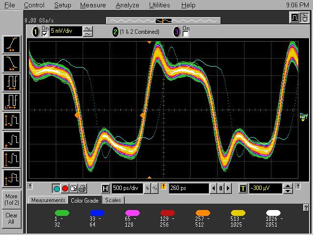
I got a bit intrigued and rebuild the Elektor design but this time using 0402 capacitors & resistors to get better HF performance and an improved board layout which should minimise the HF peaking. This posting is an update of where I'm at now. Unfortunately my design also showed some hefty peaking so I didn't got very far. A 400MHz square wave for example:


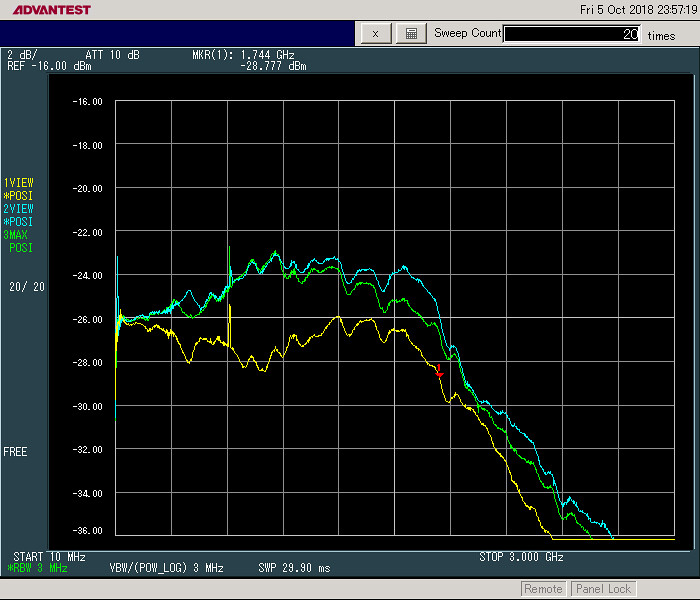
Things get even worse for a 200MHz square wave. Time to pull out the spectrum analyser and do some sweeps. Now a differential probe should show the same signal amplitude regardless the polarity of the input signal. Interestingly reversing the polarity of the input shows two entirely different traces. In one situation it peaks and in the other it drops. The effect seems to be the strongest between 700MHz and 800 MHz. A CMMR (common mode rejection ratio) measurement also shows poor performance in the same frequency range.


This turned into a bit of a head scratcher. The simulation (using the ADA4927 model from Analog Devices) doesn't show this behaviour at all and I did not manage to find the cause in the circuit board layout. It has to be something in the amplifier which isn't in the pspice model!

At one point this graph in the ADA4927 datasheet the  caught my eye:


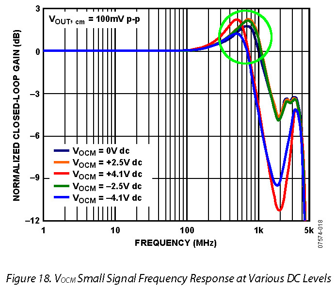
This shows the common mode amplification with peaking in the 750MHz region! And since the ADA4927 is not used differentially but as a common-mode amplifier this graph just explains everything. Some further research showed me that all so called fully differential amplifiers will suffer from this behaviour because the amplifier for the common mode has a poor frequency response. IMHO the fully differential amplifier are simply not suitable for use in a differential probe if the output is used in a single-ended way.
« Last Edit: October 14, 2018, 09:10:58 pm by nctnico »
There are small lies, big lies and then there is what is on the screen of your oscilloscope.
 
The following users thanked this post: egonotto, KE5FX

Offline Cerebus

  • Super Contributor
  • ***
  • Posts: 10576
  • Country: gb
Re: > 1 GHz DIY differential probes
« Reply #36 on: October 14, 2018, 09:17:55 pm »
I find pretty much all of nctnico's findings unsurprising. Every commercial differential probe design I've seen has frequency response trimming between both halves of the differential input (one or both sides), CMMR trim, etc. The assumption that this design makes in omitting them and expecting to get acceptable results is, IMHO, a foolish one and seems to be bourne out by measurement.
Anybody got a syringe I can use to squeeze the magic smoke back into this?
 

Offline Marco

  • Super Contributor
  • ***
  • Posts: 6719
  • Country: nl
Re: > 1 GHz DIY differential probes
« Reply #37 on: October 15, 2018, 09:18:07 am »
IMHO the fully differential amplifier are simply not suitable for use in a differential probe if the output is used in a single-ended way.
Need a GHz version of the AD8129.
 

Online dietert1

  • Super Contributor
  • ***
  • Posts: 2059
  • Country: br
    • CADT Homepage
Re: > 1 GHz DIY differential probes
« Reply #38 on: October 15, 2018, 09:49:54 am »
Happened to find this thread after completing various measurements with a probe i bought recently from A. Rosenkränzer. In my opinion the probe is useful to record a LVDS data stream, but i would not call it a 1.9 GHz differential probe. My measurements with our HP 8560A show that ADA4927 common mode is limited to about 600 MHz if you require 3 dB accuracy. The measurement shows gain on direct (faint curve) and inverting input (bright curve).
I would consider the design incomplete. For example, he writes the probe is 1:10 while it really is 1:20. 400 mV difference on LVDS results in 20 mV in the scope (with 50 Ohm terminated input).
Anyway the concept should be valid, when elaborated carefully, e.g. with metal enclosure. Maybe a LMH3401 serves better. It is specified with a common mode bandwidth of 3.3 GHz.
Regards,
Dieter
« Last Edit: October 15, 2018, 09:56:27 am by dietert1 »
 

Offline nctnico

  • Super Contributor
  • ***
  • Posts: 26892
  • Country: nl
    • NCT Developments
Re: > 1 GHz DIY differential probes
« Reply #39 on: October 15, 2018, 10:17:24 am »
The LMH3401 won't work because the minimum stable gain is >6.3 which together with the GBW product throws you back to little over 1GHz of bandwidth in an actual design. Most (if not all) of these fully differential amplifiers are designed as a front-end for fast AD converters which need a 1Vpp or 2Vpp (-ish) input signal. Also I don't think a metal enclosure will help much. All nodes in the circuit are low impedance anyway.

@Cerebus: the problem isn't in the mismatch between the inputs. I've used a symmetric PCB design and 0.1% resistors. There is no amplification so any mismatch between the inputs doesn't get multiplied. I'm convinced the problem is in the behaviour of the common mode amplifier of the ADA4927.
« Last Edit: October 15, 2018, 10:30:22 am by nctnico »
There are small lies, big lies and then there is what is on the screen of your oscilloscope.
 

Online dietert1

  • Super Contributor
  • ***
  • Posts: 2059
  • Country: br
    • CADT Homepage
Re: > 1 GHz DIY differential probes
« Reply #40 on: October 15, 2018, 10:37:09 am »
Where did you get that number "6.3"? Can't find that in the LMH3401 datasheet.
The evaluation board manual describes a 50/200 Ohm configuration (gain = 4), so i unterstood that was supposed to be stable.
 

Offline Marco

  • Super Contributor
  • ***
  • Posts: 6719
  • Country: nl
Re: > 1 GHz DIY differential probes
« Reply #41 on: October 15, 2018, 11:40:12 am »
Why not build an AC differential amplifier from a pair of RF transistors?
 

Offline tggzzz

  • Super Contributor
  • ***
  • Posts: 19470
  • Country: gb
  • Numbers, not adjectives
    • Having fun doing more, with less
Re: > 1 GHz DIY differential probes
« Reply #42 on: October 15, 2018, 01:39:31 pm »
Why not build an AC differential amplifier from a pair of RF transistors?

Or from a few bits of coax and a combiner, e.g. http://emcesd.com/pdf/cd94scr.pdf

Note: I haven't tried such a probe!
There are lies, damned lies, statistics - and ADC/DAC specs.
Glider pilot's aphorism: "there is no substitute for span". Retort: "There is a substitute: skill+imagination. But you can buy span".
Having fun doing more, with less
 
The following users thanked this post: RoGeorge

Offline nctnico

  • Super Contributor
  • ***
  • Posts: 26892
  • Country: nl
    • NCT Developments
Re: > 1 GHz DIY differential probes
« Reply #43 on: October 15, 2018, 01:46:30 pm »
Where did you get that number "6.3"? Can't find that in the LMH3401 datasheet.
The evaluation board manual describes a 50/200 Ohm configuration (gain = 4), so i unterstood that was supposed to be stable.
The number 6.3 is from the specs on the website. That corresponds with a gain of 16dB. I just checked the evaluation kit manual but I can't find any mention of configuring the chip for a gain of 4x. Creating an opamp with a high bandwidth which is stable at a gain of 1 is very hard because it needs compensation to be stable but at the same time the compensation eats into the bandwidth.
« Last Edit: October 15, 2018, 01:55:42 pm by nctnico »
There are small lies, big lies and then there is what is on the screen of your oscilloscope.
 
The following users thanked this post: Renaud

Online dietert1

  • Super Contributor
  • ***
  • Posts: 2059
  • Country: br
    • CADT Homepage
Re: > 1 GHz DIY differential probes
« Reply #44 on: October 15, 2018, 02:35:35 pm »
Yes, they use 16 dB as a basic configuration of the LMH3401 in the specs. But that is not a stability limit, see for example Figure 2 in the datasheet, which is for 12 dB and extends well up to 5 GHz. Schematic is in Figure 51. The 12 dB configuration is also mentioned in the evaluation board user manual, paragraph 4.4.
As far as i understand one advantage of the LMH3401 over the LMH5401 mentioned before is the internal feedback path which helps for stability.
 

Offline snoopy

  • Frequent Contributor
  • **
  • Posts: 767
  • Country: au
    • Analog Precision
Re: > 1 GHz DIY differential probes
« Reply #45 on: October 15, 2018, 11:11:24 pm »
The probe heads on the commercial probes such as Keysight and Tektronix are usually built using strip-line techniques on special pcb materials with consistent dielectrics used for rf design so there is quite a bit of R&D in them to get them right. I just picked up a differential probe off ebay for a good price but they are getting hard to find at good prices. Considering the new ones cost megabucks your best bet is to look for used ones that are in working order.


Offline Marco

  • Super Contributor
  • ***
  • Posts: 6719
  • Country: nl
Re: > 1 GHz DIY differential probes
« Reply #46 on: October 16, 2018, 06:22:41 am »
Those aren't high impedance though, not unless you count a couple hundred Ohms as high impedance.

GHz is in that sweet-spot where you can still have something relatively high impedance and general purpose.
 

Online dietert1

  • Super Contributor
  • ***
  • Posts: 2059
  • Country: br
    • CADT Homepage
Re: > 1 GHz DIY differential probes
« Reply #47 on: October 16, 2018, 08:10:23 am »
The offers of Keysight may be well competitive, but they forgot who are their customers: engineers and scientists. Sorry, they cannot address me with a TV spot talking about a spiral inductor and ESD protection. They don't offer a solution compatible with various makes of scopes.
The calling price of a generic 1.5 GHz differential probe seems to be $ 1500, see http://www.significantdevices.com.au. Any hands on experience?
 

Offline Marco

  • Super Contributor
  • ***
  • Posts: 6719
  • Country: nl
Re: > 1 GHz DIY differential probes
« Reply #48 on: October 16, 2018, 08:24:17 am »
Or from a few bits of coax and a combiner, e.g. http://emcesd.com/pdf/cd94scr.pdf

More expensive than a bunch of BFU660F's though. How about something simple like this? Is the simulator really giving me that bad an impression of how it would work with a tight layout and some =<0204 components? R1=R2=0 is only useful for say 10s of mV of input, probably want to bias the bases to ~4V with opamps instead of resistor dividers, might want to clamp R5-R8 with Schottkys.

PS. that Deltasense probe has nice specs, large voltage range and input impedance.
« Last Edit: October 16, 2018, 08:37:22 am by Marco »
 

Offline Cerebus

  • Super Contributor
  • ***
  • Posts: 10576
  • Country: gb
Re: > 1 GHz DIY differential probes
« Reply #49 on: October 16, 2018, 09:55:13 am »
Those aren't high impedance though, not unless you count a couple hundred Ohms as high impedance.

GHz is in that sweet-spot where you can still have something relatively high impedance and general purpose.

What are you calling "high impedance" in this context, bearing in mind that 1pF across an input @ 1GHz would equate to 159 ohms, and that the stray capacitance across an 0603 part is around 0.04pF and an 0201 part 0.02pF (the latter being ~8k @ 1 GHz)?
Anybody got a syringe I can use to squeeze the magic smoke back into this?


Share me

Digg  Facebook  SlashDot  Delicious  Technorati  Twitter  Google  Yahoo
Smf