I would love to see the schematic for the 100v range.
There isn't anything special - the output buffer amp is fed by ±150V and gain adjusted as appropriate
Having found a few old ebay auctions with better pics, and having had chance to look through the schematics for the 521 I can see a couple of differences between it and the 522
- The 521 has a 7-segment display, the 522 actually has an alphanumeric display
- The 522 doesn't seem to have provision for the 1000V option.
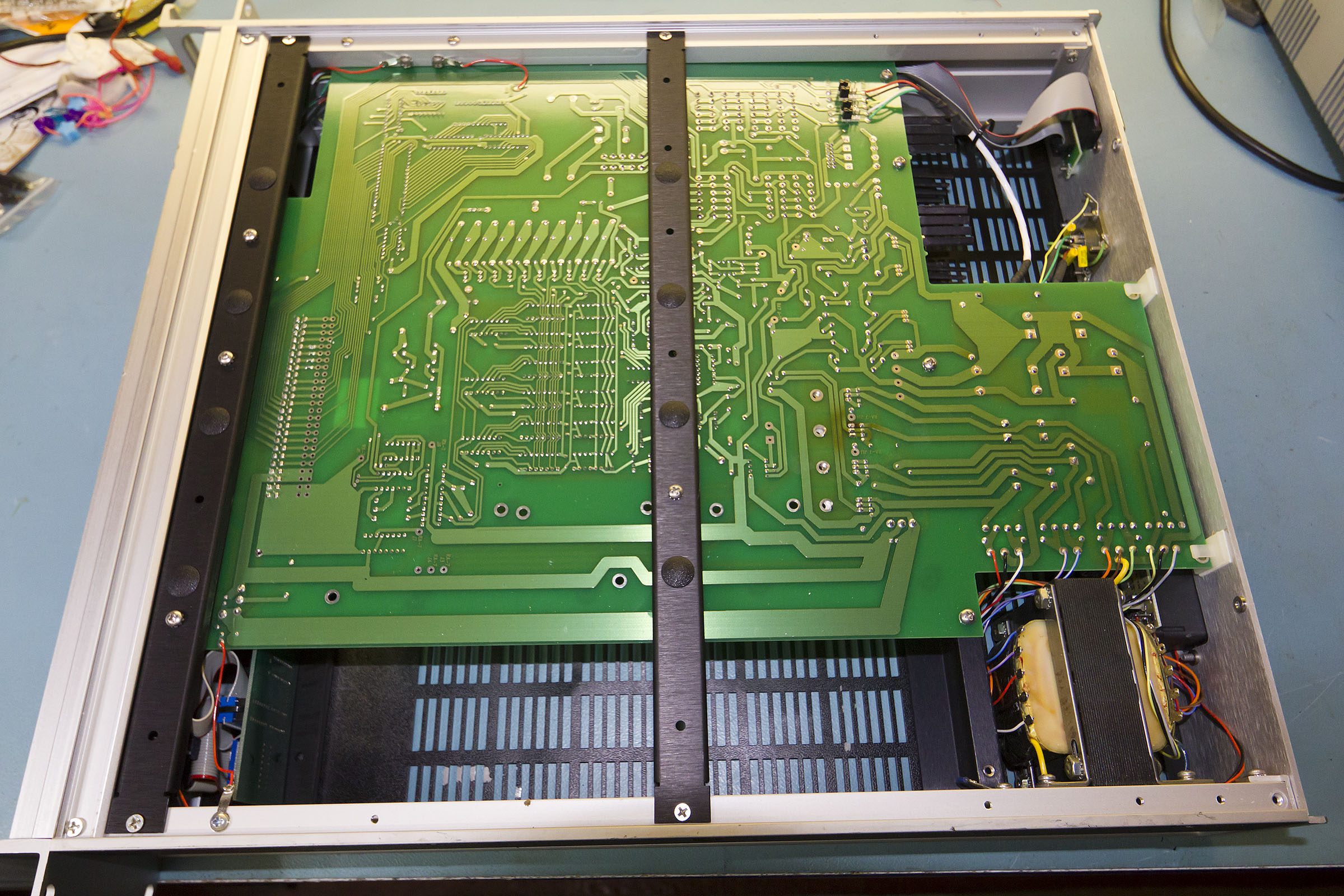
A few teardown pics:
Inside the unit (click on picture for larger version).
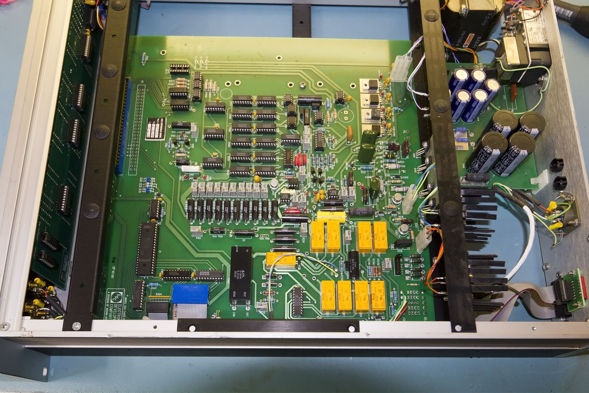
Generally it's pretty tidy inside. There is evidence of repair to one of the voltage regulators but otherwise it looks factory fresh. Date codes on ICs suggest a 1999 or 2000 build date so it's actually not that old.
The unit is built around the same voltage reference as Dave's MV106J but instead of the range switches forming a voltage divider the reference voltage is fed into a 24-bit DAC.
The DAC architecture is a bit odd in that is seems to be built as a decimal rather than binary circuit. First of all there is a 10-tap voltage divider formed from 10x precision 1k 0.01% resistors, these can be seen in a row under a set of trimmers in the centre of the picture. Each voltage tap can be tweaked with the trimmer. Then pairs of 4051 analogue multiplexers, which can be seen above the row of trimmers, are used to form 1-of-16 switches (of which 10 inputs are used). Finally the voltages from the 10 taps are summed via a six input decade weighted mixer and then passed to the buffer amp and then to the outputs.
The whole thing is controlled by a 6502 microprocessor.
It really looks like they took the basic design of the older units and just built a digital version of the front panel switches.
This is the voltage reference.
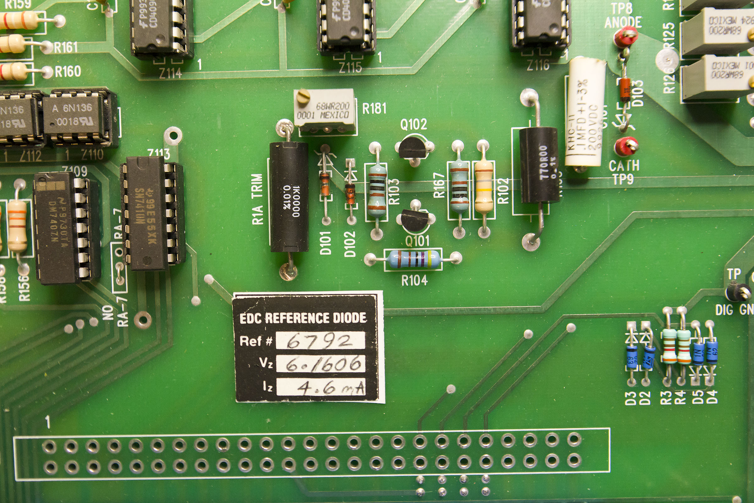
As with Dave's unit there is a little sticker with the diode parameters. Again a 1N829A is used for a 0.0005% per
oC temperature coefficient - presumably aged and hand picked. What I can't quite figure out is why the temperature coefficients of the divider chain aren't thought to worsen the diode figure. The 1K resistors are probably low tempco ones but even if they are measured and matched they aren't exactly taking care to ensure a consistent thermal environment. Trimmers have, of course, notoriously bad thermal coefficients but I suspect the saving grace with them is that they are being used as voltage dividers so any change in absolute resistance will affect the ratio of resistance between the wiper and each end much less.
Unlike Dave's the diode is just soldered into the board
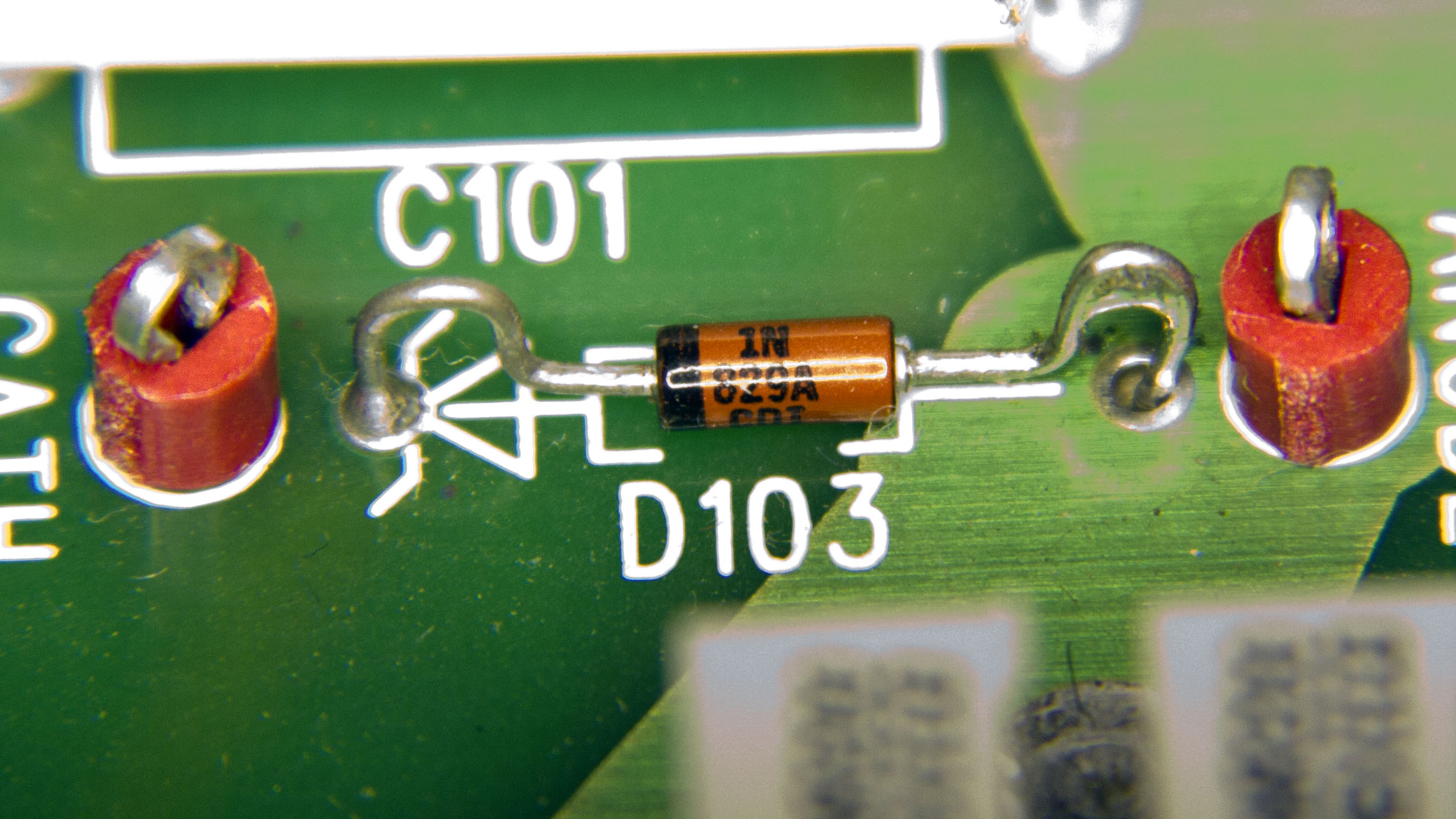
I imagine the bent leads are for strain relief.
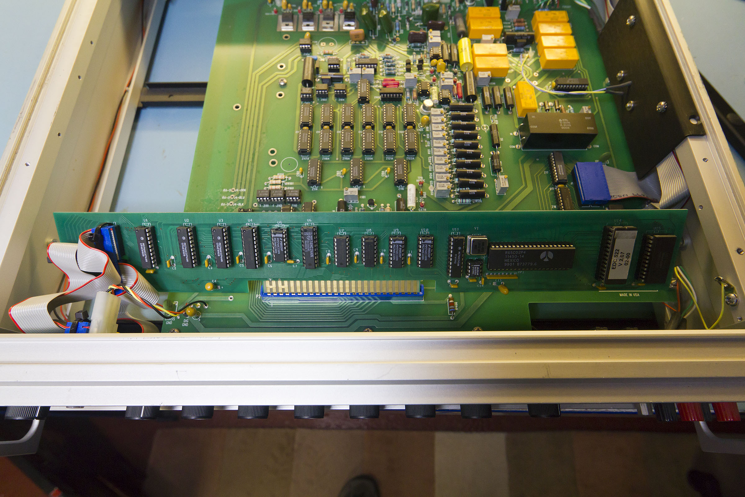
The CPU sits on a long plug in board at the front of the unit - very old school 65C02 with external ROM and RAM.
the reverse of the main PCB is not especially interesting, top right are the links which select front or rear panel output.
On the whole the design appears to be much more straightforward than the Fluke 343A, for much the same spec


