Author Topic: North Hills CS-11 Precision Current Source Teardown  (Read 2953 times)

0 Members and 1 Guest are viewing this topic.

Offline safedorkTopic starter

  • Newbie
  • Posts: 4
  • Country: us
North Hills CS-11 Precision Current Source Teardown
« on: September 30, 2018, 05:29:39 am »
Hi all,
This is my first topic, but I've been a lurker for some time, and been watching eevblog since 2008. I enjoy teardowns and understanding how things work quite a bit and I take a lot of pictures and whatnot. I was talking to a friend and they recommended that I start posting them here for others to enjoy so that's what I'm doing now. I have some devices that I wasn't able to find any teardowns of and some have very little info at all.

The first is a "north hills" CS-11 Precision current source. This is a huge and very old school unit. Unfortunately I wasn't able to find any manual for this online. I'm about 3/4 the way done writing the schematic and will post that here when it's ready. It has 5 decades and can go from 1 uA to 99.999 mA. Using it with my DMM, it seems to be pretty close to that, but I'm waiting to take some better measurements. This unit is from 1988 according to one of the voltage regulators, but the other IC's are from 1983-86 so I imagine it was in production for several years.

I'm still thinking up a good workflow for posting pictures, so I've got this as a 1024*440 pixel preview that you can click on for full resolution. All my photos are CC-BY so feel free to share with attribution.
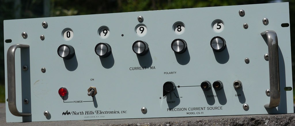

Despite being quite large, this unit is very lightweight due to being mostly empty space inside.
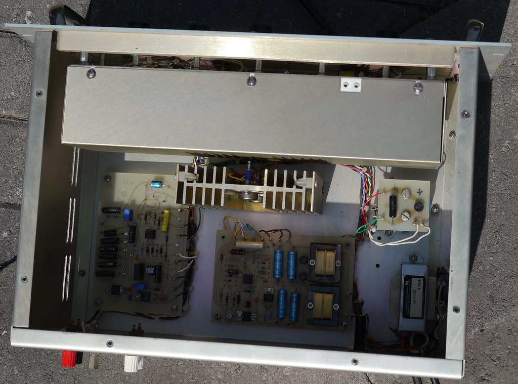


Inside you can see very old school construction. The unit is broken up into logical blocks and they are connected together with a really nice wire loom with cable ties. At the top of the frame is the shielded box with the big rotary switches and resistors in it.
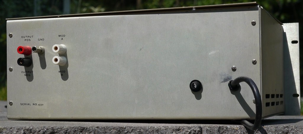

Even the rear is quite sparse with an additional output and a fuse. I don't know what the "mod" jacks do, but we'll have a better idea once I finish with my schematic.
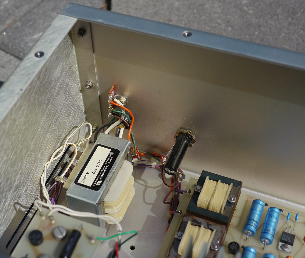

After the fuse and the switch, power comes in through this transformer which looks to be the newest thing in this unit.
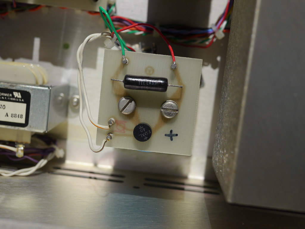

Basic and very old school regulation: diode bridge, enormous capacitor. It still takes about 10 seconds to discharge the capacitor, even with that resistor there.
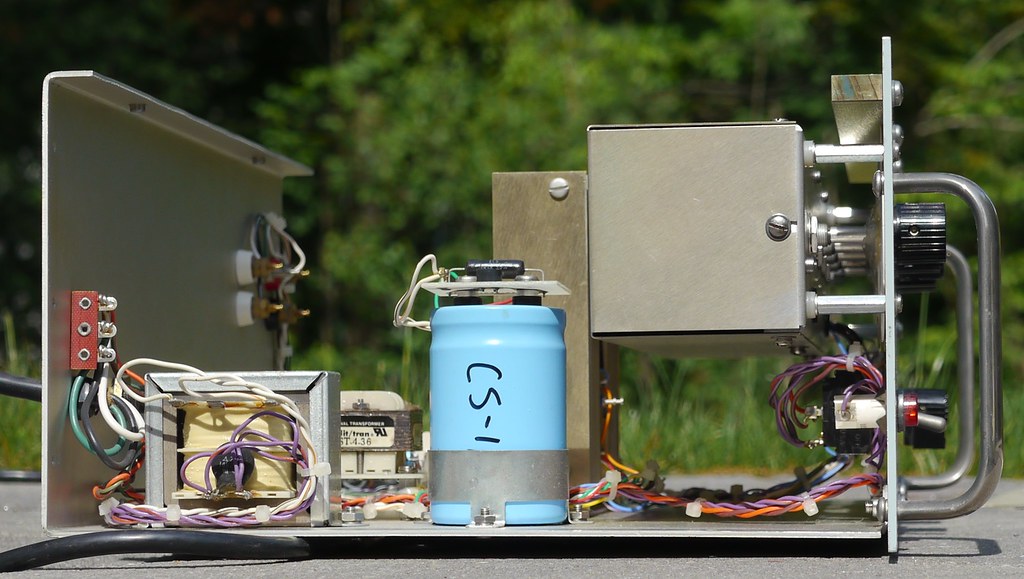

I really like the enclosure that this has, because it's very easy to work with, especially after you take the sides off. You can see the main capacitor here and it's labeled with the model number of the unit. It's a Mallory 250 V unit. Only 85C, but it doesn't really get that hot in the enclosure. It's in the MFD range, but I didn't take it out of it's holder to see what exact value.
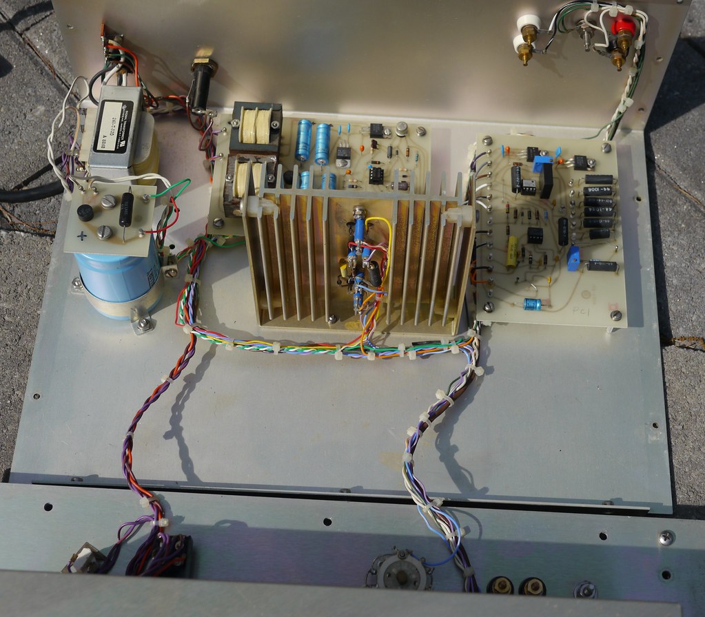

Here I have taken the front panel off to better show off the insides. It comes apart very easily. You can see those two transistors on the large heatsink and the circuitry is built off them from turrets. Was this to keep the leakage down so this unit can get it's 1 uA resolution or just a product of the times? This picture is very useful to see where all the bits of the cable loom go and how nicely they are connected together. The lower transistor is an IRF332 and the upper one is a 2n5250 (I think, my picture isn't very clear)


close up of transistor wiring. I love how bright and festive the colors are. The "crust" is flux residue that I plan to clean off next time I have the alcohol out.
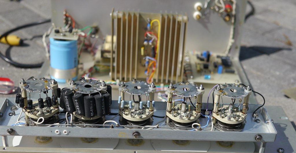

Box of resistors opened! Here you see the resistors connected to the ranging switches. You can also see the digit on the switch is just hot glued to the shaft. A few of the 10 M resistors on the left are different and look newer. Perhaps this was repaired once? You can also see the test points at the lower left here, which can be accessed when the box is closed.
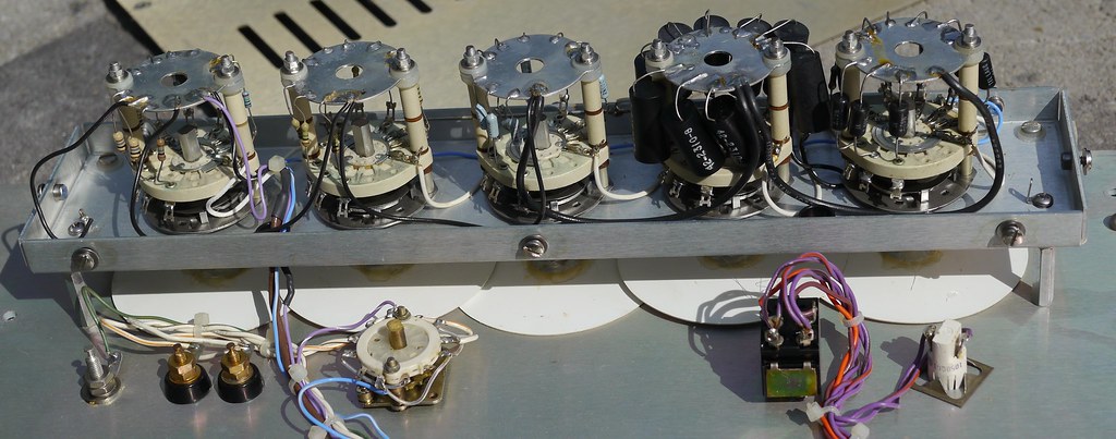

Back of the range resistors. You can also see the outputs on the lower left, the polarity switch in the middle and on the right are the power switch and power lamp. There are only 3 wires going to the resistors. the blue with white stripe, the purple with white stripe and the brown, which is coaxial. The big expensive looking ones are only on the first 2 ranges and the rest are more normal resistors. Maybe the 10 M on the left and 1M next to it for the lowest ranges precision doesn't matter as much as for the higher ranges.
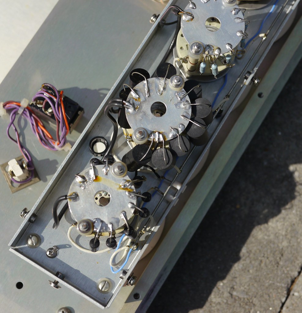

Top of the ranges. You can see how they barely managed to cram those resistors in there, and the soldering work is good to look at. Having soldered to metal, I know how hard it is, so I cut them some slack, but it's not exactly even and they didn't clean off the flux later.
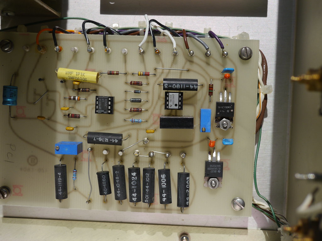

Back to the inside, this is the board I'm making a schematic for now. Since it's a 1 layer PCB it's not hard. I'm still not sure about the component right below the OP07, there is no marking on it at all. Right now the guess is that's a zener diode in a thermal box. I'm still not sure why two of those resistors have been shorted out
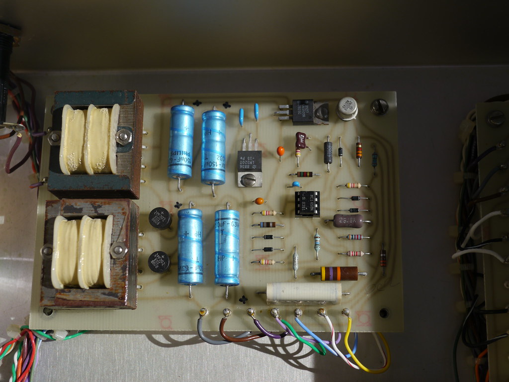

Here's the power supply for the unit. It's pretty high voltage, over 100V. I like how the capacitor polarity is labeled on the PCB by hand. I'll measure what's going on a bit better soontm. Yes that is rust on the transformers.

I'll post the schematic and wiring once I get done with it. Let me know here if you have any questions. The full album of photos can be found here.
https://www.flickr.com/photos/dork_vader/albums/72157666604137483/
 I have some other devices that I've taken apart and I'll post about them in time. I also have some others that I haven't uploaded to flickr yet. Most of the test equipment is towards the bottom.

I was going to post my kikusui PMC35-2 but the photos are terrible so I will have to reshoot them again. It's a huge pain to take apart though.

Cheers!
 
The following users thanked this post: TiN, babysitter, xrunner, Vgkid, doktor pyta, 2N3055

Online HighVoltage

  • Super Contributor
  • ***
  • Posts: 5469
  • Country: de
Re: North Hills CS-11 Precision Current Source Teardown
« Reply #1 on: September 30, 2018, 11:53:23 am »
Nice teardown
What DMM did you use to test the 1 uA range and how stable is it at 1 uA?
There are 3 kinds of people in this world, those who can count and those who can not.
 

Offline TiN

  • Super Contributor
  • ***
  • Posts: 4543
  • Country: ua
    • xDevs.com
Re: North Hills CS-11 Precision Current Source Teardown
« Reply #2 on: September 30, 2018, 12:18:40 pm »
safedork
You have my welcome to forum. Your picture flow is good, but I'd suggest to consider using your own hosting, instead of flickr. Never know when those cloud hostings decide to update their EULA and make all your pics broken.  :palm:

Very nice photos too! Perhaps next step in your worklog would be documenting test setup and providing with measurement results , so we can all enjoy and comment :)

Resistors on PCB shorted out likely as a trim for specific voltage reference output to get coarse calibration in place.
« Last Edit: September 30, 2018, 12:24:18 pm by TiN »
YouTube | Metrology IRC Chat room | Let's share T&M documentation? Upload! No upload limits for firmwares, photos, files.
 

Offline safedorkTopic starter

  • Newbie
  • Posts: 4
  • Country: us
Re: North Hills CS-11 Precision Current Source Teardown
« Reply #3 on: September 30, 2018, 11:33:50 pm »
Nice teardown
What DMM did you use to test the 1 uA range and how stable is it at 1 uA?
Thanks HighVoltage.
I haven't taken the time to let it heat up and do proper measurements on it yet (just some quick power and and adjust knobs). My best DMM for low current is my keithley 3706 which is 500+50ppm(reading +range) in the 10 uA range (at 1 year). It hasn't been calibrated recently though. That will happen next.

safedork
You have my welcome to forum. Your picture flow is good, but I'd suggest to consider using your own hosting, instead of flickr. Never know when those cloud hostings decide to update their EULA and make all your pics broken.  :palm:

Very nice photos too! Perhaps next step in your worklog would be documenting test setup and providing with measurement results , so we can all enjoy and comment :)

Resistors on PCB shorted out likely as a trim for specific voltage reference output to get coarse calibration in place.
TiN you are definitely one of my biggest influences. I read all your teardowns and fixes and greatly enjoy them all, even incomplete ones. Thank you for your kind words of welcome.

Since there is no manual, specification sheet or even a sales document, I did want to do some testing of it's capability once I get the schematic written. That'll be a lot of fun I think.

Regarding photo hosting: I've run into that issue already a few times and lost some images forever. Everything I have is now backed up multiple places here and at least one offsite. Right now I trust yahoo (flickr) to keep the images available, which is good enough for now. I'm putting in some effort to put together a website and will host everything on S3 once that's done, but I have a lot of classes right now, so it's on the backburner until next semester.
 

Offline Vgkid

  • Super Contributor
  • ***
  • Posts: 2710
  • Country: us
Re: North Hills CS-11 Precision Current Source Teardown
« Reply #4 on: October 01, 2018, 01:29:00 am »
Nice job on the teardown. Your unit looks much more conventional than my cs-152 . Looks like it uses an inverting amp, as opposed to a kelvin varley divider. Your unit also has more opamps in it than mine 3vs 1. Despite my unit being newer , but the basic design dates to the 1960's. One thing I can't find on your unit is the current senseing resistor. It should be beefy.
If you own any North Hills Electronics gear, message me. L&N Fan
 

Offline xrunner

  • Super Contributor
  • ***
  • Posts: 7517
  • Country: us
  • hp>Agilent>Keysight>???
Re: North Hills CS-11 Precision Current Source Teardown
« Reply #5 on: October 01, 2018, 01:38:43 am »
Very nice job and good clear bright pics.  :-+
I told my friends I could teach them to be funny, but they all just laughed at me.
 

Offline safedorkTopic starter

  • Newbie
  • Posts: 4
  • Country: us
Re: North Hills CS-11 Precision Current Source Teardown
« Reply #6 on: October 05, 2018, 01:25:37 am »
I finished my "schematic" of the board with the OP-07 and LM725 on it. it's below. I didn't pretty it up yet. It's the first time I've done something like this and it's pretty rough. Component values are currently missing. The image I made this from is rotated 180 degrees from the one I have here in this topic, so in the image below you can see all the binding posts and wires at the bottom, the resistor "array" is at top and the voltage regulators are at the left.
(click to embiggen).
I'm pretty sure this was repaired much later than it was made, since the blue resistor on that board + some of the ones in the switches look WAY newer than the other brown resistors there.

I'm out of time for today. I have three exams and an interview tomorrow, but I'll have time this weekend to chip at this further. Next step is to go through the wire loom and figure out how everything is interconnected, then figure out what voltages the power supply is outputting, etc.

Nice job on the teardown. Your unit looks much more conventional than my cs-152 . Looks like it uses an inverting amp, as opposed to a kelvin varley divider. Your unit also has more opamps in it than mine 3vs 1. Despite my unit being newer , but the basic design dates to the 1960's. One thing I can't find on your unit is the current senseing resistor. It should be beefy.
I couldn't find anything that looked like a big beefy current sense resistor, but I'll have a better idea when I figure out the wiring loom. The feedback resistor array on the OP07 looks like it can handle some serious power. This can only output 100 mA, which isn't "that" much (depending on the voltage). The biggest resistor in it is a black 30 ohm that's between the two big transistors on that heatsink. Looks like it can do 5W at least.

I did see your teardown when I was researching this unit and I remembered your signature so I'm glad you were able to see this post.

Very nice job and good clear bright pics.  :-+
Thanks! I was looking through my photos and I took these a long time ago (may 2016). I've learned a lot as a photographer since them. You can see (for example) that there's shadows covering things, like the front binding posts cast an odd shadow on the front panel, and some of the boards inside are obscured. A lot of my newer work is better. But I enjoy this kind of thing so I try to make the photos be clear.  :-+

Cheers!
 

Offline Vgkid

  • Super Contributor
  • ***
  • Posts: 2710
  • Country: us
Re: North Hills CS-11 Precision Current Source Teardown
« Reply #7 on: October 08, 2018, 02:05:00 am »
Found you some specs , didn't even think about checking my cs-152 manual.
This is from a 1973 catalog.
If you own any North Hills Electronics gear, message me. L&N Fan
 
The following users thanked this post: czgut

Offline safedorkTopic starter

  • Newbie
  • Posts: 4
  • Country: us
Re: North Hills CS-11 Precision Current Source Teardown
« Reply #8 on: October 22, 2018, 09:53:37 pm »
Thanks very much for the specs Vgkid. A very old design indeed, and more accurate than I had originally thought.
 
One error in the schematic I wrote is that the diode (marked ??? ) is connected between pins 3 and 4 of the OP-07, biasing the inverting input with respect to the negative power rail. I'm deciding how best to make the schematic better or just leave it as-is.

I did some performance verification of this unit vs two of my current meters (both in series, set to maximum resolution (7.5 digits for the 3706) and NPLC=1). Unfortunately either it doesn't meet its performance specification or my multimeters are off. This was just getting some quick data to get a general idea as to how accurate it is (good enough for now). The advantest cannot measure more than 19,999 mA so it was disconnected at higher currents. According to my notes I let everything warm up for 30 minutes before I took any measurements. The main reason I included the advantest is to get an idea as to how close it is to my keithley. The advantest was received DOA from eBay and I replaced a fuse. It is about 300 PPM off the keithley except in very low ranges. I soldered up a custom triax to bnc cable (ignoring the guard of the triax) and used a BNC to banana adapter to connect the instruments. This is my no means a precise setup, I just wanted to get an idea.

CS-11Keithley 3706Advantest%diff kei%diff adv
0unstableunstable
0.001unstableunstable
0.0022.040342.0371.977121461.816396662
0.0033.034533.031.1379027390.99009901
0.0044.042294.0381.0461891650.941059931
0.0055.021015.0140.4184417080.279218189
0.0065.994675.981-0.088912317-0.31767263
0.0076.974286.953-0.368783588-0.675967208
0.0087.919377.905-1.018136544-1.201771031
0.0098.890938.875-1.226755806-1.408450704
0.0110.0418710.0260.4169542130.259325753
0.0219.9035319.901-0.484687892-0.497462439
0.0329.9532829.94-0.15597624-0.200400802
0.0439.8006139.79-0.500972221-0.527770797
0.0549.905349.89-0.189759404-0.220485067
0.0659.7059559.69-0.492496979-0.519349975
0.0769.5241469.51-0.684452911-0.704934542
0.0879.3376979.32-0.834798694-0.857286939
0.090.089134589.12-0.971004493-0.987432675
0.10.099971999.95-0.028107898-0.050025013
0.20.1999303199.88-0.034862149-0.060036022
0.30.2998665299.8-0.044519811-0.066711141
0.40.3998233399.7-0.044194523-0.075056292
0.50.4997792499.7-0.04417951-0.060036022
0.60.5997497599.6-0.041734077-0.066711141
0.70.6997214699.6-0.039815847-0.057175529
0.80.7997184799.6-0.035212395-0.050025013
0.90.8997473899.5-0.028085664-0.055586437
10.99961999.4-0.039015216-0.060036022
21.9988161998.7-0.059235067-0.065042277
32.9981912.998-0.060336383-0.066711141
43.9975763.998-0.060636746-0.050025013
54.9969634.997-0.060776916-0.060036022
65.9963565.996-0.060770241-0.066711141
76.9956846.996-0.061695182-0.057175529
87.9950567.995-0.061838216-0.062539087
98.9944288.995-0.061949465-0.055586437
109.9975619.998-0.02439595-0.020004001
2019.9956119.991-0.021954819-0.045020259
2019.99546disconnected-0.022705154
3029.994-0.020004001
4039.98791-0.030234138
5049.98503-0.029948967
6059.99028-0.016202625
7069.98182-0.025978175
8079.97288-0.033911496
9089.9671-0.036568924
99.99999.95806-0.040957177
(thanks to https://theenemy.dk/table/ for easy BBCode table creation )

I did also measure the voltages along the side of the power board (with the two transformers on it) and the side of the "amp board" (with the op-07 on it). These were all with respect to the (-) terminal of the big blue mains capacitor. all taken with eevblog 121gw

power board
wire colormeasured voltage
grey15.178
brown13.239
purple43.418
lavender/green0
light blue/white142.11
white/red142.13
yellow142.72

amp board
wire colormeasured voltage
purple43.42
grey15.178
brown13.208
white9.994
black/white9.993
white9.994
(nothing)9.994
black0
black/white0
(nothing)11.602
black0
orange11.498
(nothing)0

+ rail for the opamps is 30.339V and - rail at 0.
The OP-07 feedback resistor measured 3.6272k (in circuit but unpowered).
Measuring the voltage at the output with my multimeter gives 139.1V which is a little higher than the 100V specified.
Note that the output of the op-07  (first "white" cable on the amp board) is suspiciously close to 10V. I might get a better multimeter on it.

While powered I measure 186.8V on the main capacitor. After 10 seconds after turning it off the voltage was still 94V. After 60 seconds it was still 6.3V. Definitely don't mess around here!

Next step here is to figure out how the front panel resistor decades are connected to the rest of the unit. I do know they go through a shielded cable to the rear panel, but I'm unsure how it connects from there. It uses the same brown shielded cable that is in Vgkid's cs-152. Then I will write how the transistors fit into the mix. I'll probably do that tomorrow morning before class.

Since I can't really calibrate this unit until I get a multimeter calibrated, I'll probably move on to a new teardown after this unless someone has interest. I may use this to help me learn how to do some fun GPIB logging once I get that system set up. The keithley has some really powerful options to control it. I can then run the stability test.
 

Offline Vgkid

  • Super Contributor
  • ***
  • Posts: 2710
  • Country: us
Re: North Hills CS-11 Precision Current Source Teardown
« Reply #9 on: October 22, 2018, 11:19:10 pm »
Check the polarity difference on the readings. It lead to several percent error(until cleaned/replaced) on mine/pigrews, others units.
If you own any North Hills Electronics gear, message me. L&N Fan


Share me

Digg  Facebook  SlashDot  Delicious  Technorati  Twitter  Google  Yahoo
Smf