Author Topic: Teardown - Hitachi V1065  (Read 43935 times)

0 Members and 1 Guest are viewing this topic.

Offline grumpydocTopic starter

  • Super Contributor
  • ***
  • Posts: 2905
  • Country: gb
Teardown - Hitachi V1065
« on: January 26, 2014, 11:48:03 pm »
I happened across another Hitachi V1065 recently so thought I'd take a few pics this time as I checked it out.

Hitachi made several 'scopes and the V1065 is one of a series of very similar instruments made in the mid-late 80's. It's a 100MHz bandwidth analogue 'scope with cursor readout. They're actually very nice 'scopes to use although there is a bit of "one knob does everything" going off with some of the settings. The tubes are very nice and have an utterly pin-sharp trace. They are also a nice 'scope should you need to do any DIY fault finding as they are almost completely standard parts (except the custom CPU).

Manual including schematics at http://www.wild-pc.co.uk/docs/Hitachi-V-1585-65-60-V-695-OM-Schematics-English.pdf

There was a thread recently on what constitutes a teardown - this is more a take-apart than teardown but I still find it useful to see how something goes together. As it happens there was no great problem with the 'scope - the small selector switch used to control the function of the "variables" knob was sticky and didn't return cleanly to the centre position - getting the front panel PCB out to get at it to clean/lubricate it needs pretty much the whole 'scope taking apart.

In fact this is really a tear-up as I'd got the whole thing apart before I thought of taking any photos - so they were done in reverse order as I put it back together.

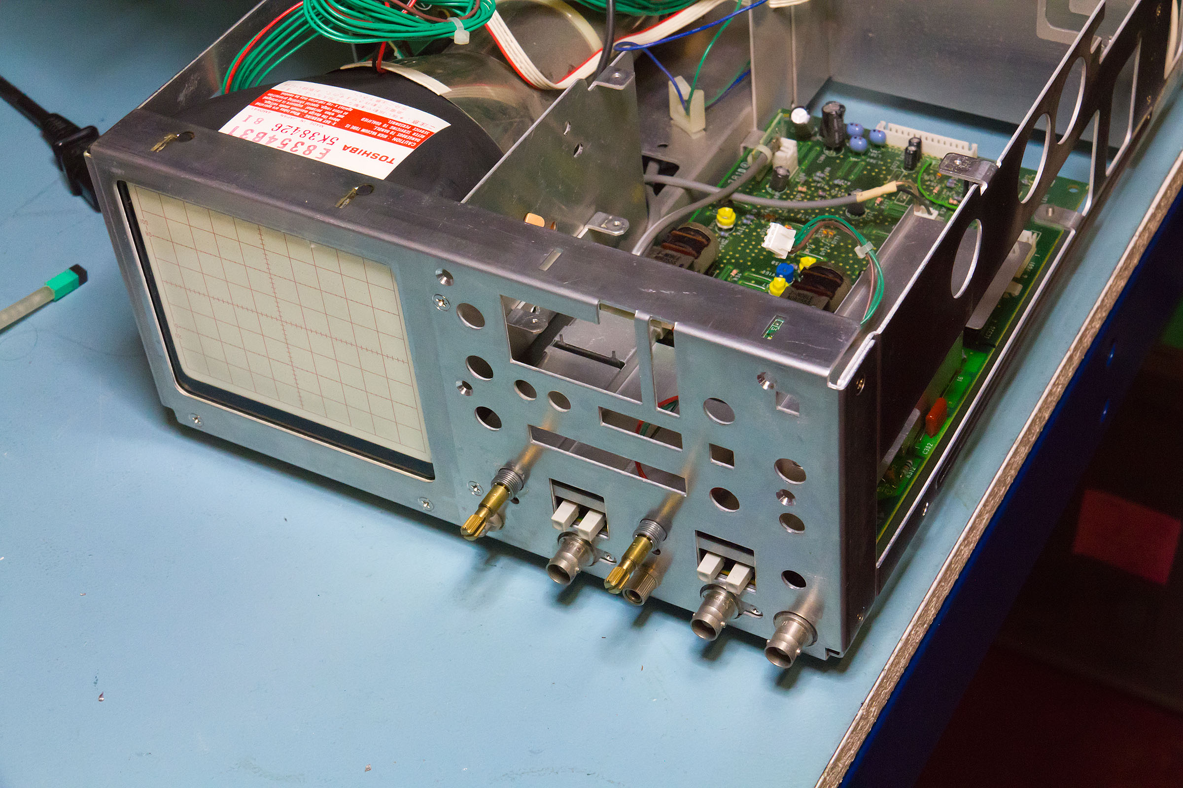
Overall view (click on pictures for high res version).


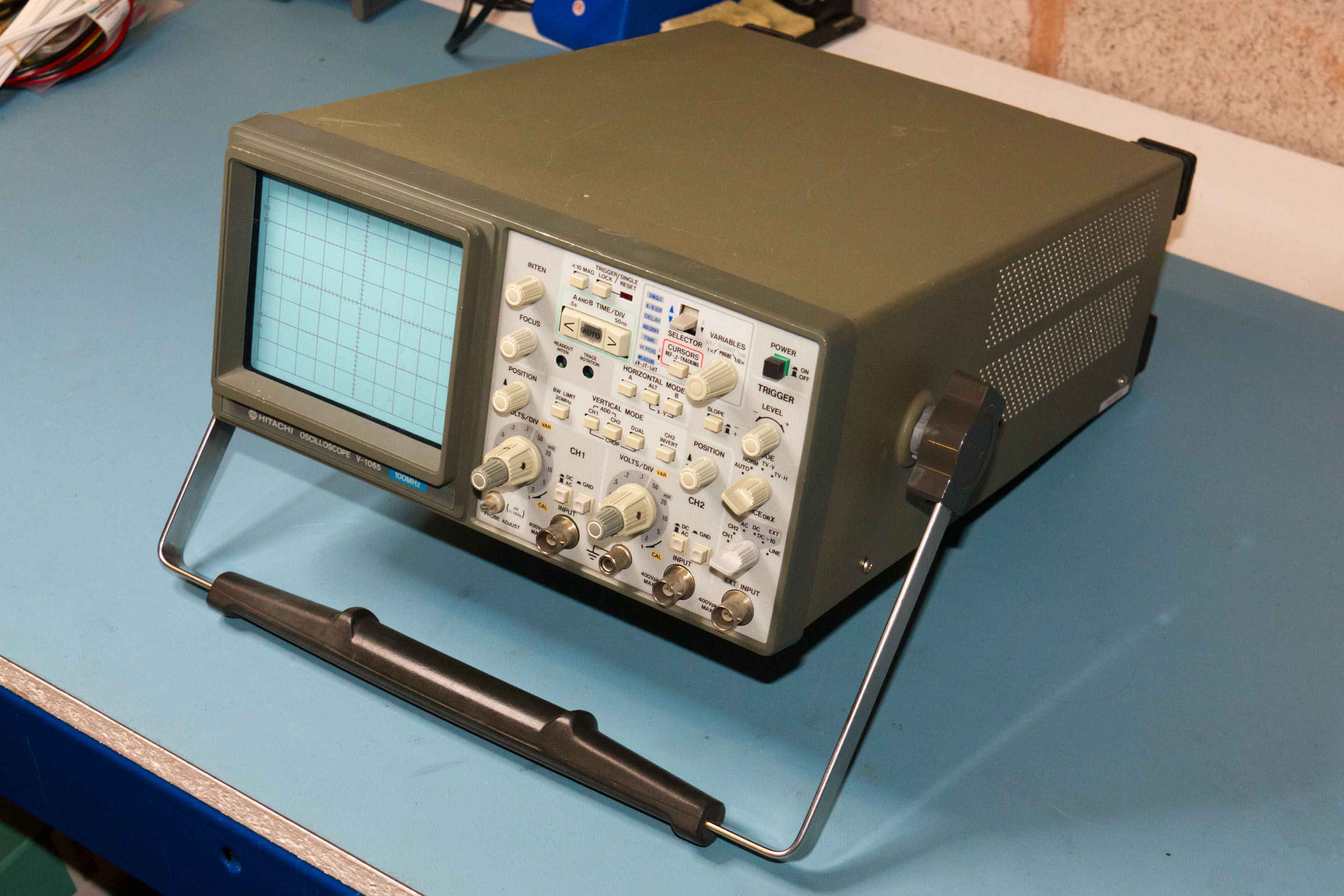
Whilst obviously not as small or lightweight as a modern DSO these are very compact. Military green seems to be the only colour though :)

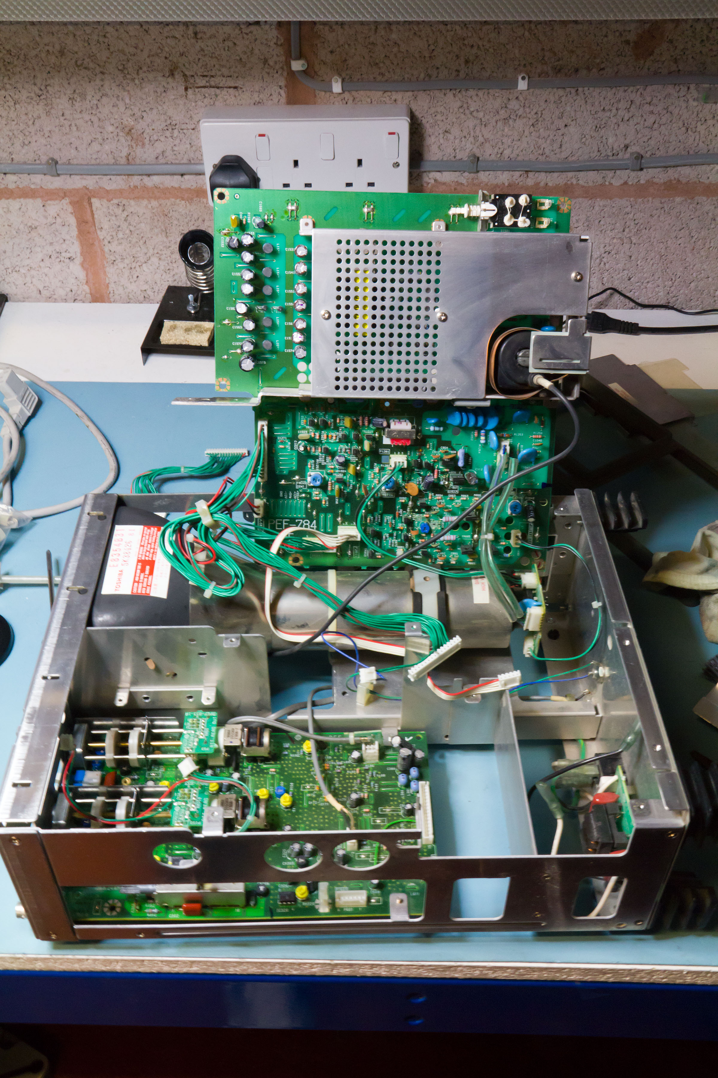
Taking a peek inside


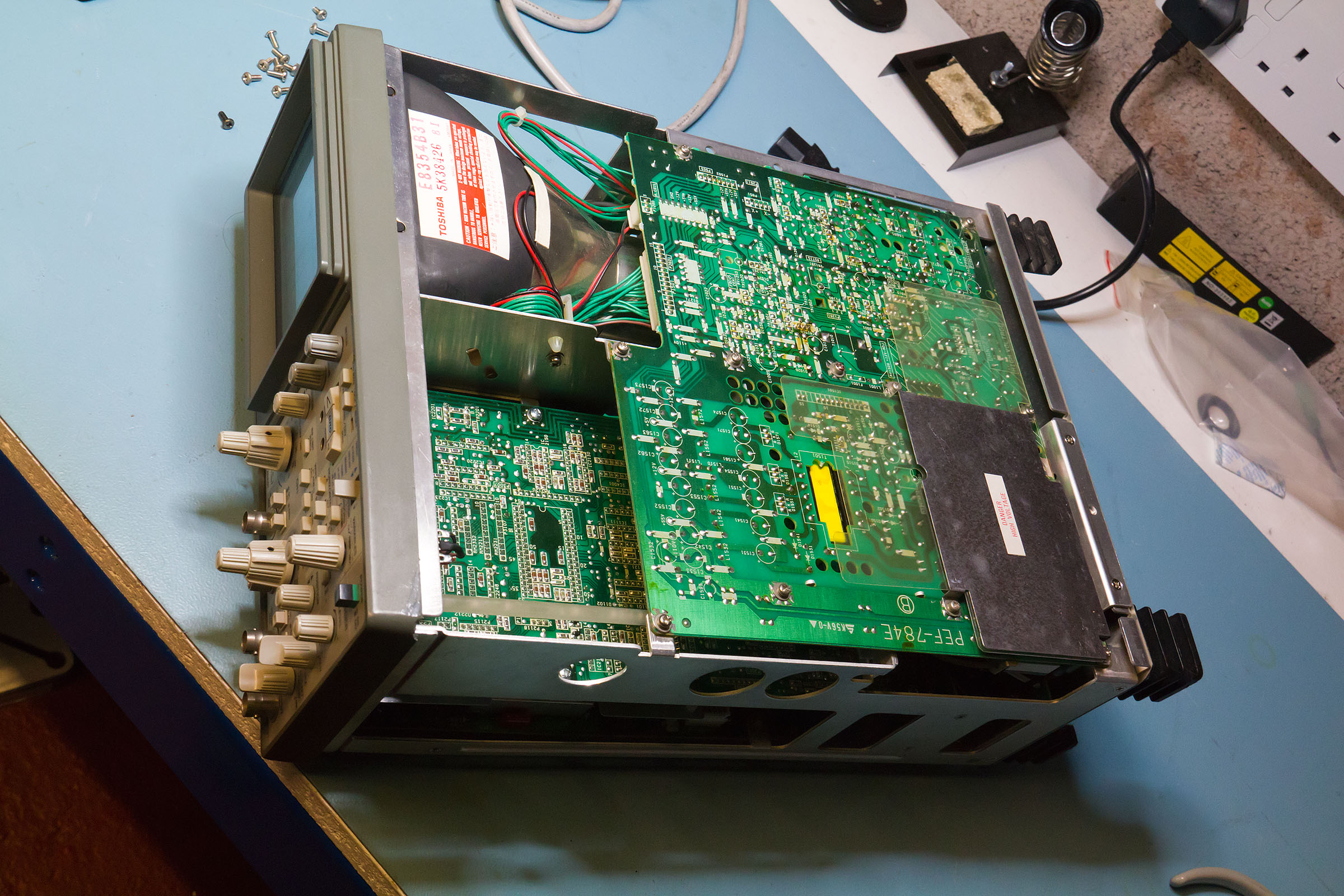
The top board is the PSU including all the high voltage sections - there is some protection for these but I don't think I'd want to accidentally put my hand on here with the thing powered up. The final X amp and Z-mod circuits are here as well.

The PSU board has a hinge mechanism which allows it to swing up towards the front of the 'scope. I'm not sure if the intent was that he instrument could be run powered up like that as it's hard to get to the CPU/X board to fault find but if so then it's a bit of a fail. The two mains input leads and another inter-board connect are way too short to allow the PSU board to swing up.

I find it's easier to swing the PSU board out to the side. In fact the 'scope can be powered up like that if the mains input to the board is extended (and one is very careful with the position of the board - lying the board flat on the bench with the 'scope on its side works best).

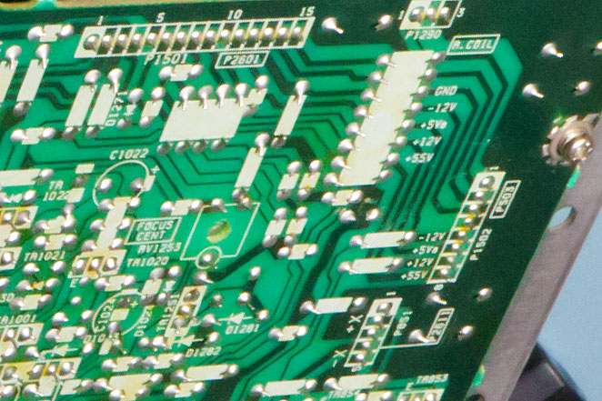
The back of the PSU board has nicely labelled points to check the supply voltages.


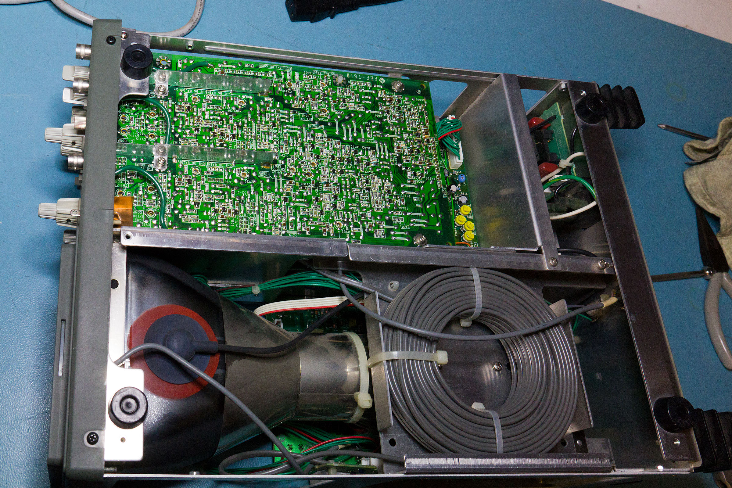
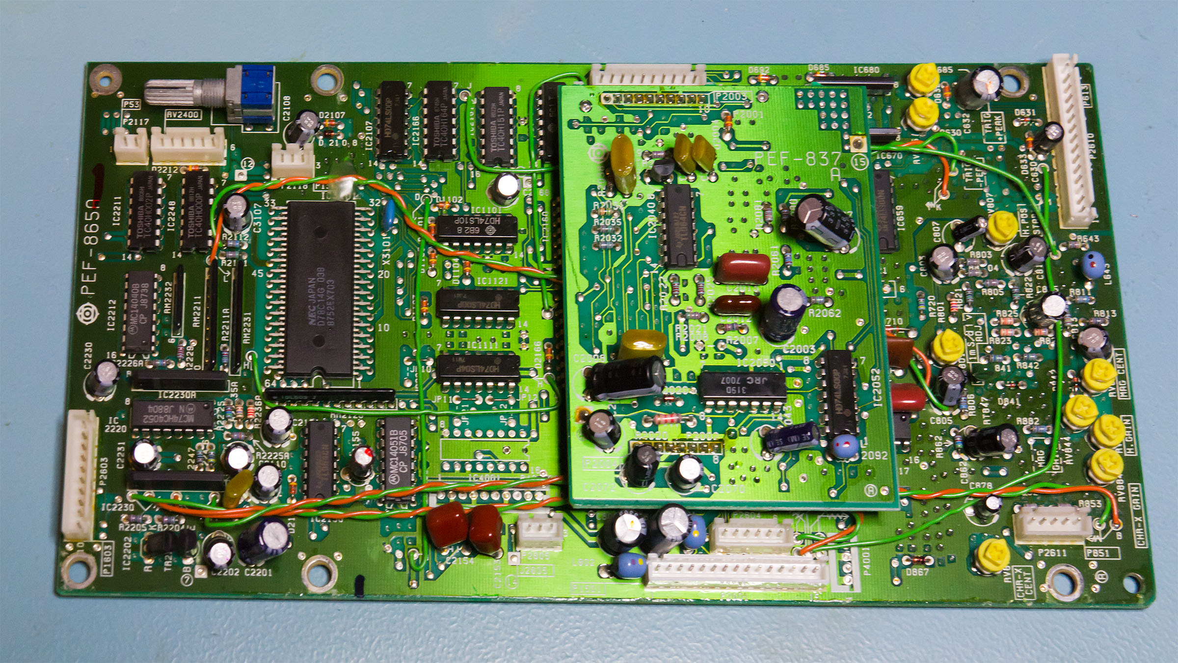
Swinging the PSU out of the way shows the next board down which is the CPU/horizontal board.


Construction is a mix of SMT and through hole. Most (but not all) of the passives are SMT with the ICs (mostly 74LSTTL on the CPU board) in DIP packages.

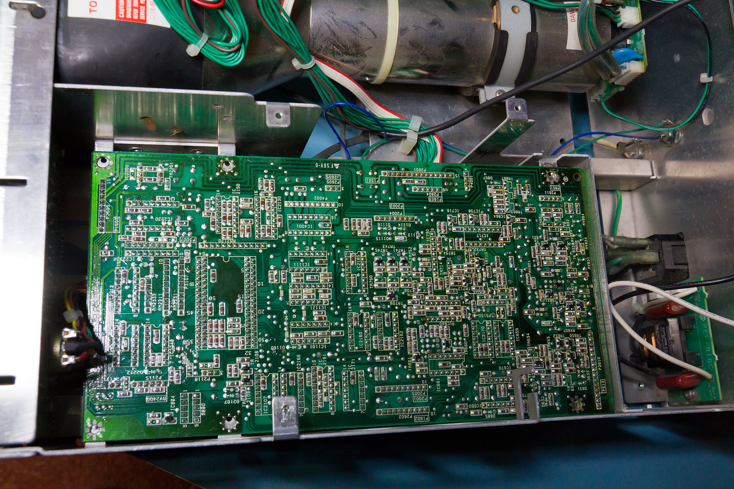
Flipping the whole thing over shows the solder side of the vertical board and the delay line - which looks huge compared with the ones in the Tek 2200 series 'scopes.


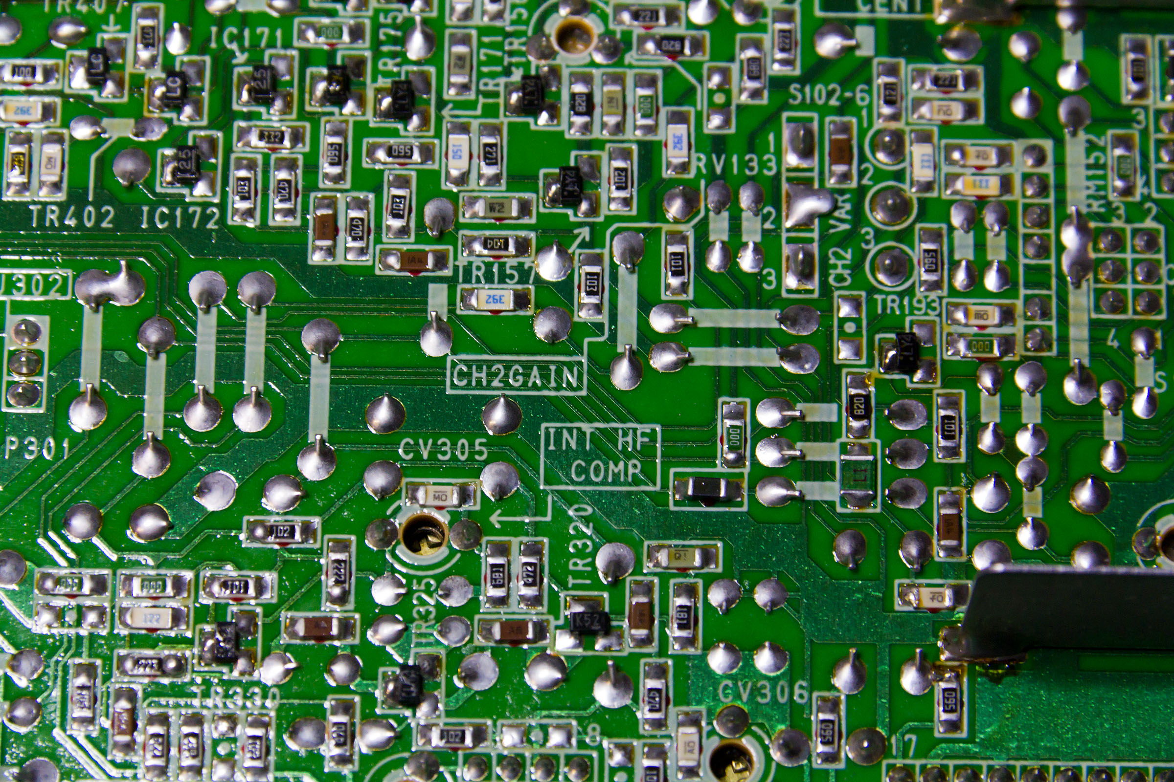
You can just see the yellow trimpots for calibration on the horizontal board - all in the same area of the board. In fact you can get at these by taking off just the bottom of the case.

The vertical calibration points are all on the component side of the board but with holes through to allow access. They are all nicely marked on the solder mask as well.


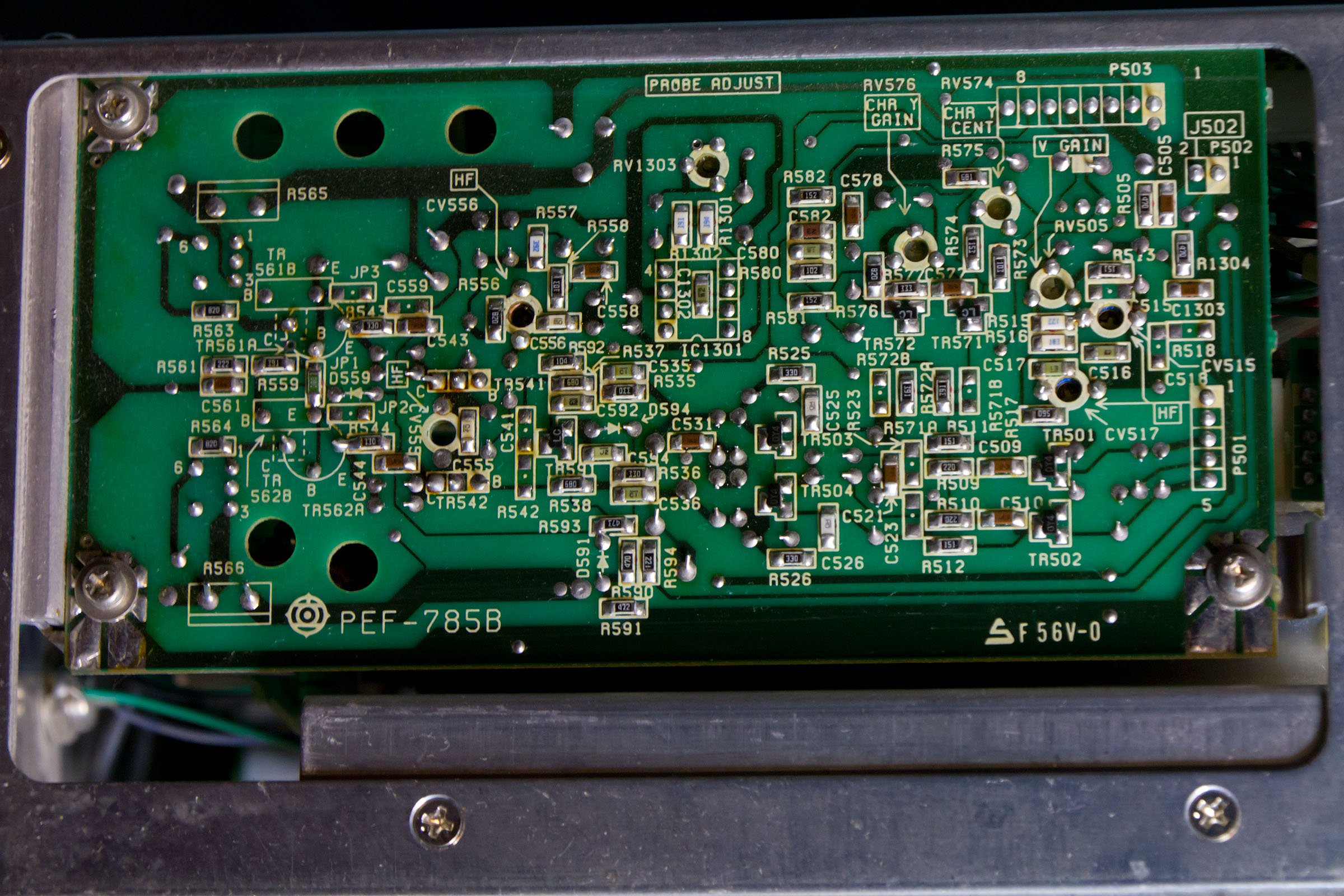
Round the side is the final Y amp. You can only really see the solder side of this board as it's close to the end of the CRT. Again the functions for all of the variable caps and resistors is marked on the silk screen.


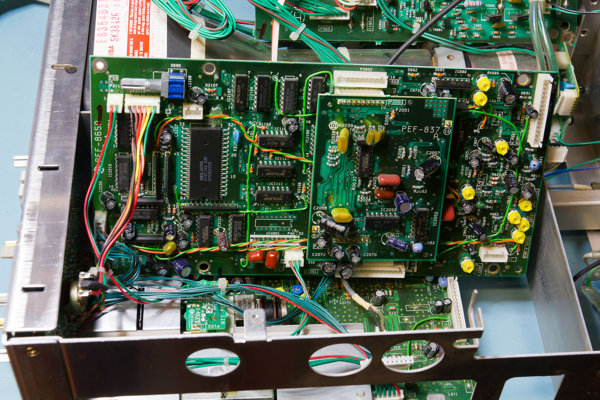
Trying to get the CPU board out is made harder by the fact that not all of the interconnects are long enough - it gets just far enough out to start to disconnect everything


Once a few are unhooked it's possible to swing the board up. Almost all of the header plugs are different sizes so it's fairly easy to make sure everything is going to the right place on reassembly.


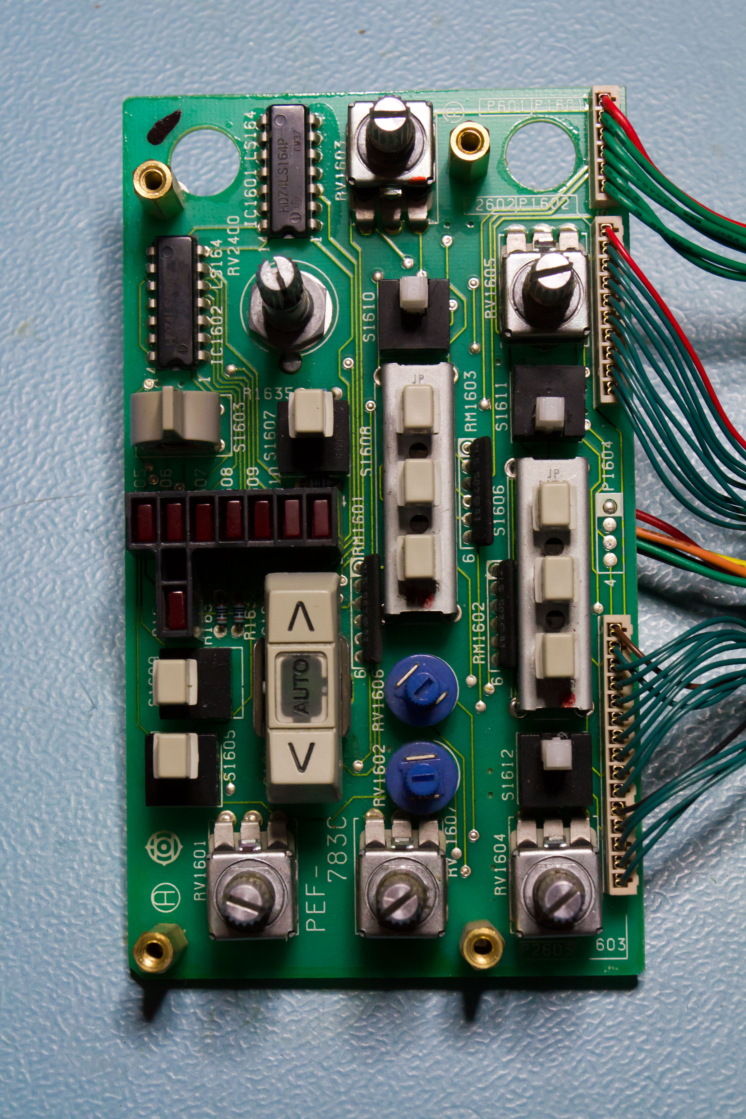
Finally we have the boards out and the chassis is looking a bit bare but we can get at the gummed up switch. Strictly speaking I didn't need to take the plate off which forms the visible front panel but it badly needed a clean.


The offending item is the toggle switch just above the array of LEDs - underneath the paddle there's a fairly normal centre biased toggle. A quick squirt of switch cleaner and a bit of light lubrication and it's as good as new.


The CPU is an NEC D78C14G micro-controller. Odd 64 pin "quad" DIP package which was briefly used in the late 80's before (thankfully) disappearing. It appears to be a bit Z80ish but doesn't have compatible machine code. Date codes on the ICs suggest a mid 1988 build date for the 'scope as a whole.


Datasheet for the CPU at 
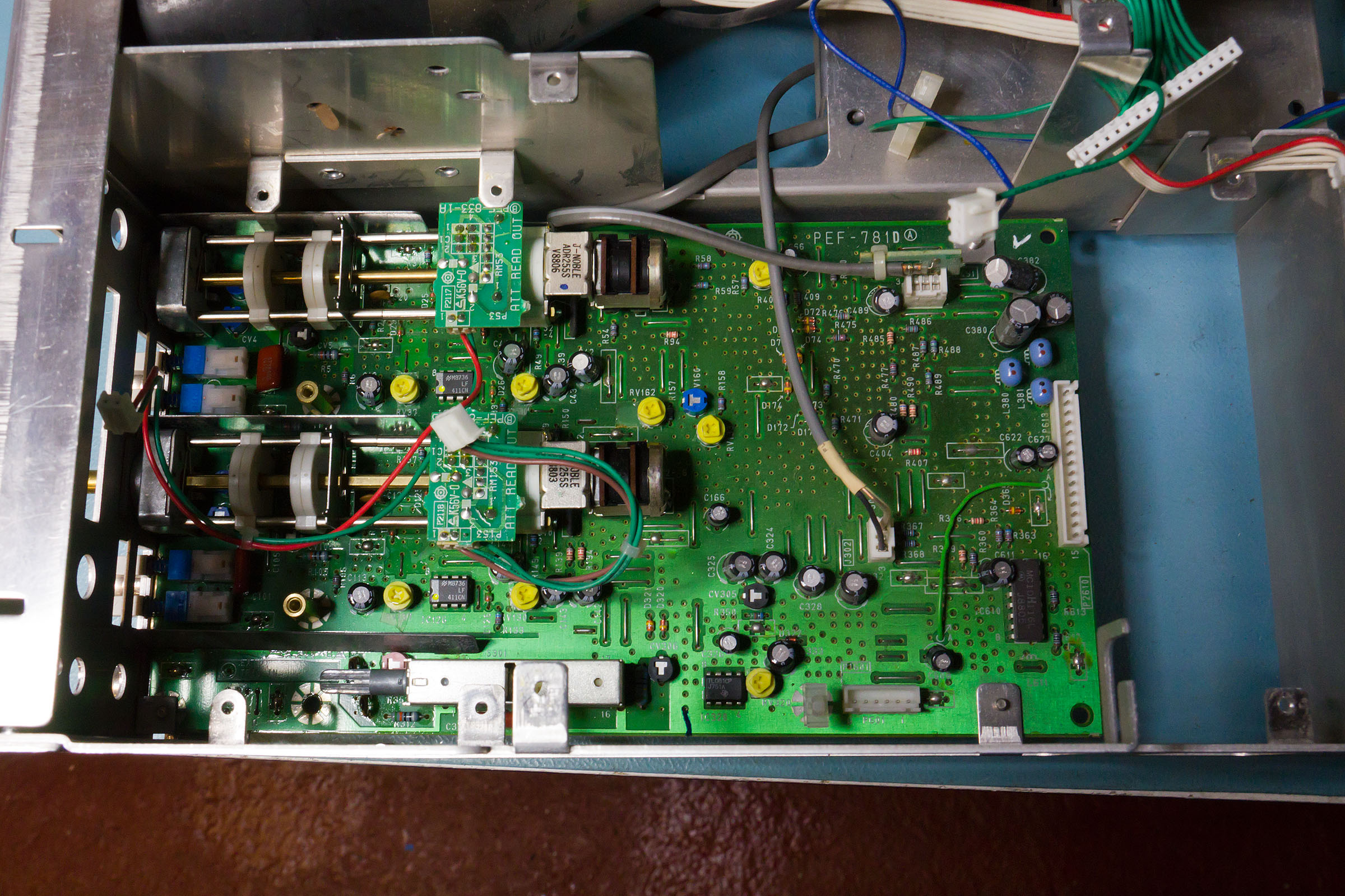
http://www.wild-pc.co.uk/idocs/NEC_D78C14G.pdf

Looking down at the top of the Y board we can see the readout boards which tell the CPU which attenuation has been set, otherwise there isn't actually much to see on this board.


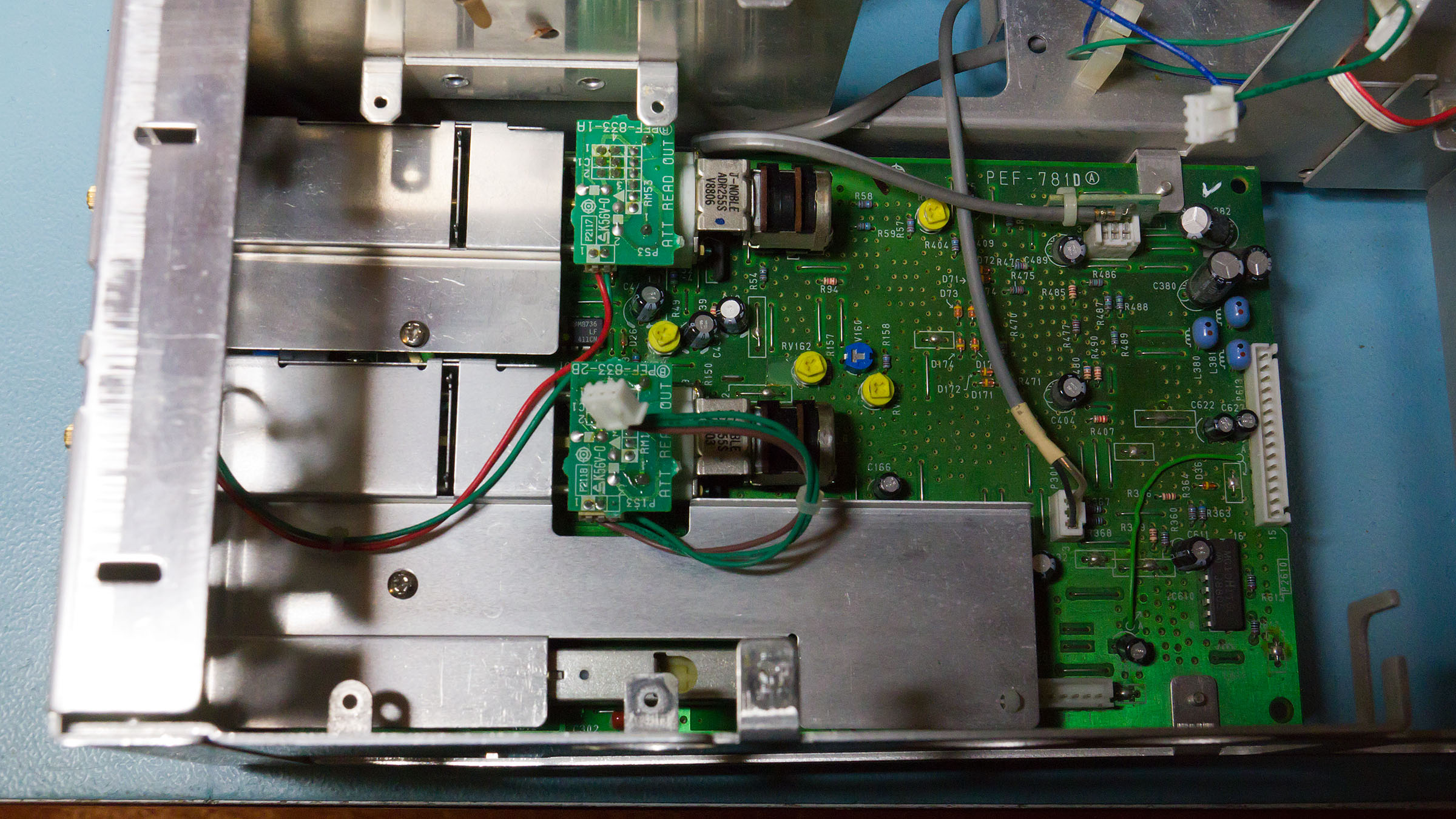
Even with the screening removed the board is fairly boring.


Finally a shot showing how I swung the PSU board out of the way. The high voltage side is screened off (it almost touches the CPU board when everything is installed.


The screening mostly hides the two transformers.


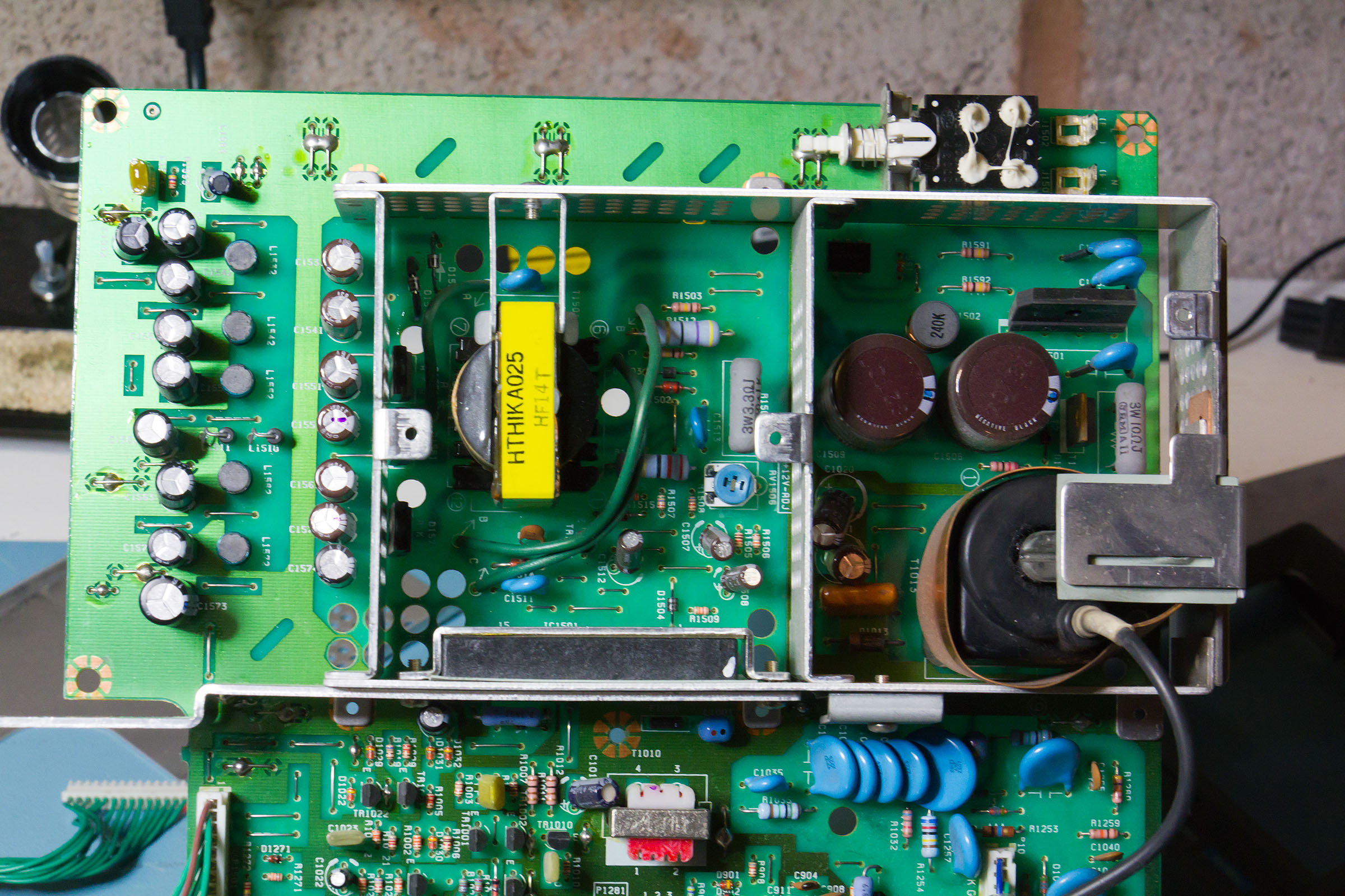
The CRT anode potential is 15kV. Slightly unusually this is generated straight from the HV transformer - there is no multiplier (at least if the schematic is to be believed).

Finally back together and running


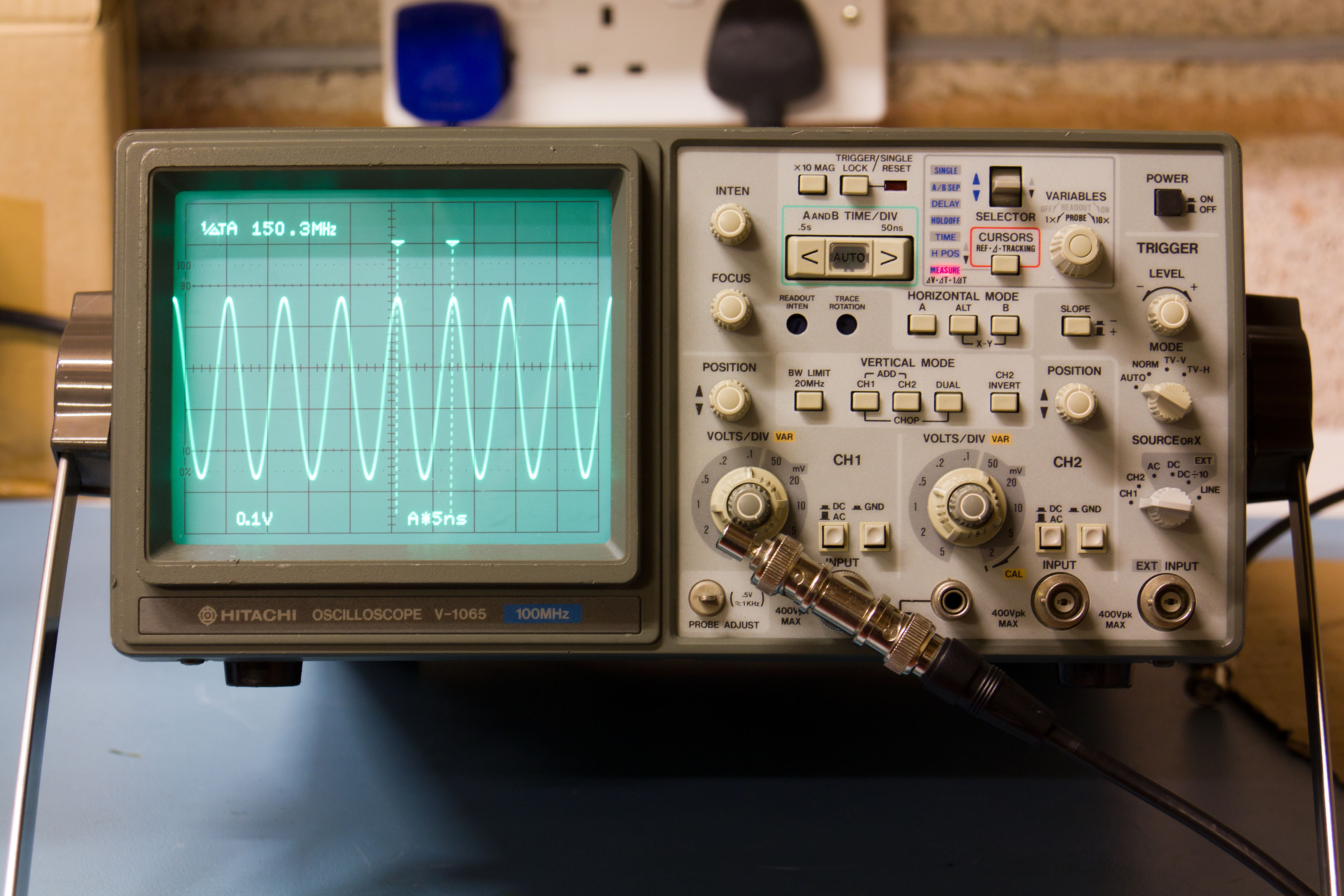
For a notionally 100MHz 'scope it does rather well - though the frequency response is a bit odd. It's about 2-2.5dB down at 100MHz but then drops slowly to not quite 3dB down at 124MHz before increasing a bit for a few MHz, then falling again and finally hitting -3dB about 150MHz, then tailing off as expected. Max stable trigger is around 150MHZ (although it's a bit tricky to get a clear display at this frequency).

Hope you enjoyed the teardown folks :)


« Last Edit: January 27, 2014, 08:42:52 am by grumpydoc »
 
The following users thanked this post: The_Paya, battlecoder

Offline true

  • Frequent Contributor
  • **
  • Posts: 329
  • Country: us
  • INTERNET
Re: Teardown - Hitachi V1065
« Reply #1 on: January 27, 2014, 08:35:11 am »
Thanks for the photos and description.

These scopes sometimes come up as a deal (they don't say "Tek" on them so nobody wants them) - I have two myself, a 1065 and 1065A (has a frequency counter).

I did a bit of a teardown myself to try to fix some audible high-pitched noise in the 1065A...even swapped the PSU board and CRT between the scopes (the 'A was pretty well used but the non-A was near new) but it didn't really make a difference. Oh well, they work... I was wondering if I can unlock freq mode on the 1065 non-A though? Didn't care enough to proceed with that one...

That switch and the timebase buttons were gummed up in both of mine. (Timebase would work, but Auto would not work reliably until I cleaned the buttons.)

The link to the CPU datasheet is 404.
 

Offline grumpydocTopic starter

  • Super Contributor
  • ***
  • Posts: 2905
  • Country: gb
Re: Teardown - Hitachi V1065
« Reply #2 on: January 27, 2014, 08:53:46 am »
Thanks for the photos and description.

These scopes sometimes come up as a deal (they don't say "Tek" on them so nobody wants them) - I have two myself, a 1065 and 1065A (has a frequency counter).
Thought it was the 1065C which had the counter.

Quote
I was wondering if I can unlock freq mode on the 1065 non-A though?
There's an extra board which goes in the "C" so it's probably not just a question of "unlocking" the functionality.

Quote
That switch and the timebase buttons were gummed up in both of mine. (Timebase would work, but Auto would not work reliably until I cleaned the buttons.)
The attenuator switches can get gummed up as well - the ones here wern't too bad so I left them.

Quote
The link to the CPU datasheet is 404.
Fixed.
 

Offline true

  • Frequent Contributor
  • **
  • Posts: 329
  • Country: us
  • INTERNET
Re: Teardown - Hitachi V1065
« Reply #3 on: January 29, 2014, 07:04:57 am »
Quote from: grumpydoc
Thought it was the 1065C which had the counter.
Not aware of 1065C... not many search results for that. The 1065A certainly has the frequency counter. It works like any other frequency counter. Not a whole lot of resolution but in my brief tests a while back it was quite accurate and pretty quick. Will have to test again...

I do remember that the counter is tied to the trigger.

Quote from: grumpydoc
There's an extra board which goes in the "C" so it's probably not just a question of "unlocking" the functionality.
There is no extra board that I see in my 'A or even additional chips which is why I was thinking it may be something unlockable :) but I didn't look very hard. Or maybe it's just different firmware...

Quote from: grumpydoc
The attenuator switches can get gummed up as well - the ones here wern't too bad so I left them.
Yeah, but that's true on any scope really :) My 'A knobs are pretty well shot - they work but they don't snap into place very well. My non-A, after cleaning, feels like new.
 

Offline grumpydocTopic starter

  • Super Contributor
  • ***
  • Posts: 2905
  • Country: gb
Re: Teardown - Hitachi V1065
« Reply #4 on: January 29, 2014, 08:30:18 am »
Quote
Not aware of 1065C... not many search results for that.
It's referenced in the manual and the only difference seems to be the frequency counter. "C"=Counter, presumably. I've never actually seen one.

I suppose the "A" was a revision and they just threw the counter in and only had one model.

In the schematic an extra ROM board is mentioned which is only present in the 1065C, I presumed there was a bit of extra firmware for the frequency counter, plue perhaps some pre-scaling before feeding the signal into one of the counter/timer inputs. The schematic isn't all that clear - after a 5 minute look I'm not sure whether they could have implemented the counter that way - I need a bit longer staring at the diagram.

I'm not sure why that makes your 1065 and 1065A look the same - I'd ask for photos of the CPU boards but they're not exactly easy to get out.

Do you know if there's a service manual anywhere for the "A"?

Quote
I do remember that the counter is tied to the trigger.
Yes.
 

Offline grumpydocTopic starter

  • Super Contributor
  • ***
  • Posts: 2905
  • Country: gb
Re: Teardown - Hitachi V1065
« Reply #5 on: January 29, 2014, 07:00:05 pm »
OK have done some digging.

Not sure whether you had this anyway but I found a service manual covering the V1065A which can be downloaded here

This lists the variants of the 100MHz 'scope as V1065A and V1060, the "V1065A" having cursors and frequency counter and the V1060 having neither.

The manual I originally had (and posted a link to) covers the V1065, V1065C and V1060. As above the V1060 has neither cursor readout or frequency counter, the V1065 has cursors and the V1065C has both.

Unfortunately there is no date information from which to work out which is the newer of the two service manuals.

It would appear that the V1065 and V1065A are in two different series of 'scope - which would suggest there is no "simple upgrade" path between the two. In the 1065C variant there is an extra board - "ROM PG CKT" - which carries a 16K (EP)ROM and some address latches.

There are various links (R2113, R2114 and R2171-76) on the CPU board which tells the firmware which 'scope it is installed in, for the 1065/1065A/1065C R2113&2114 are the same (both open) and the others are set as follows:

10651065A1065C
R2171000
R2172openopenopen
R2173000
R2174openopenopen
R2175open00
R21760openopen?

The "open?" is because the schematic actually says "*" which I'm presuming to mean open given the 1065A values.

So, it's possible that if you swap R2175 and R2176 (but don't have both shorted as that will short the 5V rail) a 1065 will think it's a 1065C - however I think it's quite likely that it will then try to read some code from the extra ROM board - if this isn't present than that is likely to end badly.

If you fancy giving it a try let us know what happens.


« Last Edit: January 29, 2014, 11:30:36 pm by grumpydoc »
 

Offline true

  • Frequent Contributor
  • **
  • Posts: 329
  • Country: us
  • INTERNET
Re: Teardown - Hitachi V1065
« Reply #6 on: March 02, 2014, 02:01:49 am »
Finally got some time to hack on this. Sorry it took a month. :(

I couldn't find anything telling me where these resistors were on the board, since there are no markings on the board and the PDFs didn't show the positions for most passives (or I am blind) so I looked for groups of 0-ohm jumpers. Hitachi used green ones so they were easy to find. I opened the 1065A and compared, noticed a jumper in a different position, so I changed that on the 1065.

IT WORKED! I now have a frequency counter on the 1065 non-A. It's the 4th option of the cursor mode. Since you have a non-A, I will describe where it is:

Take off the cover, and move the PSU board slightly out of the way - up and over without disconnecting cables is fine. With the front of the scope facing you, on top of IC2161 silkscreen you will see pads for 2 resistors (one populated) and below that pads for 3 components (a cap and two resistors). On the 1065, on the line of pads with the cap, the 0-ohm jumper is on the outside... it goes [CAP] [empty] [0-ohm] - move the 0-ohm over into the empty position. So it should be [CAP] [0-ohm] [empty] - this will enable the frequency counter.

As for cal, it's close enough for any sort of work I might imagine I would do with this. 10MHz showed 9.992, above that it started getting worse (59.94 at 60MHz), but below 1MHz was really spot on. (The 1065A is basically spot on until 100MHz, as high as I tested it). It's probably just a calibration thing.

Thanks for investigating this. :)

---

Actually I edited your board photo; here's what needs to be done.

« Last Edit: March 02, 2014, 02:07:48 am by true »
 
The following users thanked this post: ch_scr

Offline grumpydocTopic starter

  • Super Contributor
  • ***
  • Posts: 2905
  • Country: gb
Re: Teardown - Hitachi V1065
« Reply #7 on: March 02, 2014, 08:28:38 am »
Quote from: true
Finally got some time to hack on this. Sorry it took a month. :(

....

IT WORKED! I

Wow  8) that's useful to know. Thanks for trying it and for the update.

Quote from: true
Thanks for investigating this. :)

No problem.

Actually I've now sold the 1065 and it's on its way to a new owner but picked up four V1565's to play with  :)

These are AFAICS the same 'scope but white and with the frequency counter enabled, unfortunately one had a mangled BNC on channel 2 so I'm just in the process of replacing it. Not the easiest job since the whole 'scope has to come apart to get the bottom vertical board out.


Offline algorath

  • Contributor
  • Posts: 19
  • Country: at
Re: Teardown - Hitachi V1065
« Reply #8 on: March 02, 2014, 08:54:46 am »
kewl teardown vintage goodness
 

Offline true

  • Frequent Contributor
  • **
  • Posts: 329
  • Country: us
  • INTERNET
Re: Teardown - Hitachi V1065
« Reply #9 on: March 02, 2014, 05:14:59 pm »
Actually I've now sold the 1065 and it's on its way to a new owner but picked up four V1565's to play with  :)

These are AFAICS the same 'scope but white and with the frequency counter enabled

1565 is basically exactly a 1065A with a wider voltage input power supply and different colored plastics. I wouldn't mind one because every 1065 I've seen is beat up...maybe people took better care of 1565s? (though judging by "mangled BNC" maybe not)
« Last Edit: March 02, 2014, 05:26:26 pm by true »
 

Offline grumpydocTopic starter

  • Super Contributor
  • ***
  • Posts: 2905
  • Country: gb
Re: Teardown - Hitachi V1065
« Reply #10 on: March 02, 2014, 06:02:48 pm »
Quote
I wouldn't mind one because every 1065 I've seen is beat up
The three I've had (a 665 and two 1065) have been OK and not needed much more than a decent clean up. The 665 was sold as "no readout" but it just turned out that the grid bias had been set so as to make it impossible (or nearly so) to get the readout to show.

Cosmetically the only real problem was that the 665 and the recent 1065 had an almost identical chip out of the back of the front plastic bezel in the to right corner.


The couple that are on ebay at the moment do look a bit beat-up I admit, one with very yellowed knobs as well. In fact I have a 1060 which I'm now resigned to being a parts 'scope as the HT transformer is missing which has fairly yellowed knobs. The two I sold and the 1565's are perfect. That said the 1565's are newer  - probably around 2001-2002. I can't decipher the date codes on the Hitachi TTL and there are very few non-Hitachi ICs in it. A couple have "00" date codes and one could have an "02" data code.

As 'scopes go I like them - they have nice CRTs. You can get an absolutely pin sharp trace out of them.
 

Offline true

  • Frequent Contributor
  • **
  • Posts: 329
  • Country: us
  • INTERNET
Re: Teardown - Hitachi V1065
« Reply #11 on: March 02, 2014, 09:51:45 pm »
Cosmetically the only real problem was that the 665 and the recent 1065 had an almost identical chip out of the back of the front plastic bezel in the to right corner.


MINE HAVE THAT CHIP TOO :( Only on the right side. Wonder why that is.

Every 665/1065/1565 I have seen in person has been in terrible shape though...but most also seemed heavily used, not bench queens like some Teks I own...

Quote from: grumpydoc
As 'scopes go I like them - they have nice CRTs. You can get an absolutely pin sharp trace out of them.
Agreed.
 

Offline grumpydocTopic starter

  • Super Contributor
  • ***
  • Posts: 2905
  • Country: gb
Re: Teardown - Hitachi V1065
« Reply #12 on: March 02, 2014, 11:58:29 pm »
Quote
(though judging by "mangled BNC" maybe not)
Well, it was definitely mangled


As usual click on the pictures for a larger version.

Actually, as I had to get the Y board out here are some more photos - of the 1565 but you wouldn't really know just looking at the boards. To get the Y board out you have to remove the bezel, knobs, printed face-plate and the retaining nuts on the attenuator switches. It's then possible to pull the board backwards and down (after removing the four screws holding it to the chassis. It's easier to unhook all the inter-board connects if the CPU board has been removed first, i.e it's pretty much strip everything out time.

The BNC's are actually attached to a separate bracket


This is, entertaining to remove - not only  are there 5 screws holding it to the Y board there is copper screening which is soldered to the board as well as the connections from the BNCs themselves.

The above pic shows the bracket with the "new" BNC installed. I was just going to grab one from the parts bin but then discovered that a) the ones I had were slightly shorter (so would look out of place) and b) had the flat surfaces at right angles rather than opposite sides of the thread (so wouldn't fit). So I decided to strip down the 1060 that I have and take one from it.

Looking at the shot above I really wish I'd changed the bracket with all three BNC's because the fact that the one from the old 'scope doesn't quite match escaped me until I'd got everything back together  :palm: The reason I didn't was more-or-less because the old BNC needed a polish and a thorough wash out with IPA but, actually, it's come up better looking than the newer ones.

Looking at the Y board now it's out of the 'scope it seems quite simple compared with many 'scopes.


The action is mostly on the reverse and it's basically all SMD - the design is probably late 80's and it's interesting to compare with the Tek 22xx series which were only a couple of years earlier and almost completely through hole.


Finally a shot of the BNCs reunited with the Y input board


You can see the copper shield as well as a separate ground wire. Not sure why both are needed.

At last the 'scope is back in one piece - the frequency meter is good to about 125MHz - after that it gets a bit confused although the 'scope will actually trigger OK up to about 150MHz. I can get on with the calibration now, as well - although the 5ns timing looks OK - 40ns for 5 cycles of 125MHz is spot on.


The donor 'scope isn't looking quite so healthy though


While slightly tedious I'll put it back together tomorrow - that way I know where all the bits are when I need them again.


« Last Edit: March 03, 2014, 08:36:02 am by grumpydoc »
 

Offline anjimoo

  • Newbie
  • Posts: 4
Re: Teardown - Hitachi V1065
« Reply #13 on: March 10, 2014, 01:11:05 am »
Hi, thanks for this teardown. It's been very helpful so far. I also have this scope and this switch is giving me a lot of trouble. Unfortunately after disassembling it I've had no luck fixing the switch by cleaning it. Whatever I do it's never returning to center, instead snapping hard to the up or down positions. It's also hard/unpredictable to move up or down.

The scope is fine otherwise so I'd love to fix this switch somehow. Maybe I can replace it? It's a "Fujisoku AL2S" apparently. I can't find much of anything about it though :(. Maybe anyone recommend me a new component that will replace this switch? I'm not that experienced with electronics so I don't know exactly what to look for.

Thanks!
 

Offline true

  • Frequent Contributor
  • **
  • Posts: 329
  • Country: us
  • INTERNET
Re: Teardown - Hitachi V1065
« Reply #14 on: March 10, 2014, 01:20:20 am »
How did you clean it? I had one that would stick completely - I put switch cleaner in the switch and worked it pretty aggressively... it works pretty well now.

But if it is well and truly broken, you may need to figure out what the pinout of the switch is. It may be necessary to make an adapter board...

Or maybe you could ask grumpydoc to give up the switch from his parts unit? :)
« Last Edit: March 10, 2014, 01:24:01 am by true »
 

Offline anjimoo

  • Newbie
  • Posts: 4
Re: Teardown - Hitachi V1065
« Reply #15 on: March 10, 2014, 01:26:48 am »
I pretty much drenched the switch in contact cleaner. So far it hasn't changed anything. It just refuses to return to the center unless I delicately maneuver and hold it there.
 

Offline true

  • Frequent Contributor
  • **
  • Posts: 329
  • Country: us
  • INTERNET
Re: Teardown - Hitachi V1065
« Reply #16 on: March 10, 2014, 03:05:16 am »
Then it is likely broken :(

If you can determine the pinout I can maybe help find a switch...no time for this myself, but I I looked but didn't find any direct replacements. With a pinout I could spare a few minutes to hunt for a switch.
 

Offline anjimoo

  • Newbie
  • Posts: 4
Re: Teardown - Hitachi V1065
« Reply #17 on: March 10, 2014, 03:26:49 am »
I think I've found out how it's wired. Input is on the middle pin on the left of the switch (the one connected to the resistor) on the back of the board, output is on pins labelled 4, 5 and 6 depending on the state of the switch. It appears to be all continuous. As far as I can tell the other pins on the switch are unused.

Hmm I should've noted which position corresponds to which pin :P .. But I've currently reassembled it .. I'll pull it apart again tomorrow to check.
« Last Edit: March 10, 2014, 03:41:42 am by anjimoo »
 

Offline true

  • Frequent Contributor
  • **
  • Posts: 329
  • Country: us
  • INTERNET
Re: Teardown - Hitachi V1065
« Reply #18 on: March 10, 2014, 04:41:38 am »
If you can, label your image and I'll see what I can find. If nothing can be found you might need to make an adapter.
 

Offline grumpydocTopic starter

  • Super Contributor
  • ***
  • Posts: 2905
  • Country: gb
Re: Teardown - Hitachi V1065
« Reply #19 on: March 10, 2014, 08:26:37 am »
Use a switch cleaner which has lubricant

Make sure you have given the ball at the end of the toggle a good squirt - I think that's where they get gunked up.

Work the switch a couple of times until it comes free.

Possibly add a tiny bit of light machine oil (not 3-in-1).

If not and you're in the UK then PM me and we might be able to work something out with regard to a replacement.


Offline Nidhoeggr

  • Newbie
  • Posts: 1
  • Country: de
Re: Teardown - Hitachi V1065
« Reply #20 on: March 16, 2014, 02:46:10 pm »
Hi,

I recently got a Hitachi VC-6045 DSO and I also have the issue with an annoying noise from the PSU board, which true mentioned before. Do you furthermore tried to fix it? It's strange, that you didn't solved it with changing the PSU board. That means the source of the problem is somewhere else?

I located (as far as I could) the sound at the Pulse Amp Transformer T1010 (btw. the schemtatic of the PSU & HV generation board is pretty much the same at the first look in comparison with the V1065) and maybe a bit also comes from the HV transformer, but it's very hard to find the exact spot, where it's coming from.

The supply voltages are fine and the DSO itself work brilliant too, but the noise drives me crazy when I measure over longer periods.

If you guys have any approaches to solve this, I would be very thankfully.

Greetings
Philipp


PS: Sorry for the bad english, I'm from germany ;)
 

Offline true

  • Frequent Contributor
  • **
  • Posts: 329
  • Country: us
  • INTERNET
Re: Teardown - Hitachi V1065
« Reply #21 on: March 23, 2014, 06:59:38 pm »
I never figured out the high freq noise issue, as the 1065 now has a freq counter and I'll probably get rid of the 1065A.

This said, I can't find a way to calibrate the frequency counter at all. Don't see anything to adjust on the board that might be related, nor do I see anything in the service manual / schematics... maybe it's some matched components somewhere, sigh... the values do remain pretty close to constant between power-ups and length of time powered up, so maybe I can hack something in somewhere...
 

Offline grumpydocTopic starter

  • Super Contributor
  • ***
  • Posts: 2905
  • Country: gb
Re: Teardown - Hitachi V1065
« Reply #22 on: March 23, 2014, 08:49:00 pm »
Quote
This said, I can't find a way to calibrate the frequency counter at all.
No, I don't think that there is. Presumably it relies on the CPU clock  which is probably fine given the resolution is only 4 digits.
 

Offline Hydrawerk

  • Super Contributor
  • ***
  • Posts: 2600
  • Country: 00
Re: Teardown - Hitachi V1065
« Reply #23 on: March 23, 2014, 11:40:06 pm »
Amazing machines. https://www.youtube.com/user/denha (It is not me...)
 

Offline true

  • Frequent Contributor
  • **
  • Posts: 329
  • Country: us
  • INTERNET
Re: Teardown - Hitachi V1065
« Reply #24 on: March 24, 2014, 12:28:41 am »
Quote
This said, I can't find a way to calibrate the frequency counter at all.
No, I don't think that there is. Presumably it relies on the CPU clock  which is probably fine given the resolution is only 4 digits.

From what I can see in the circuit description, it depends on the trigger circuit, not the CPU. I am a decent amount off, not just a few digits.


Share me

Digg  Facebook  SlashDot  Delicious  Technorati  Twitter  Google  Yahoo
Smf