Author Topic: Tektronix 2465B oscilloscope teardown  (Read 654452 times)

0 Members and 3 Guests are viewing this topic.

Offline BravoVTopic starter

  • Super Contributor
  • ***
  • Posts: 7547
  • Country: 00
  • +++ ATH1
Tektronix 2465B oscilloscope teardown
« on: November 01, 2011, 06:57:59 am »


Acquired recently this scope at local tech surplus store,  and even its quite old now, still, it should be pretty good piece of equipment. Among peers & friends here, we called this Jim's scope cause Jim Williams (in memoriam) used it too at his personal bench table.

I have another similar thread, but its for asking some details -> https://www.eevblog.com/forum/index.php?topic=5258.0 , and decided to post the teardown photos in this new thread instead of there.

Here we go, teardown and preliminary inspection, since I'm going to recap the whole scope and took shots for documentation and component inventory purposes.


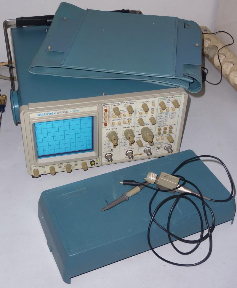
The whole bundle, with the top pouch, front cover and a single Tektronix P6136 350Mhz probe. Every thing is nicely preserved by previous owner, I was told it was previously used in clean r&d lab at a big consumer electronic factory.


Click to enlarge the pictures.


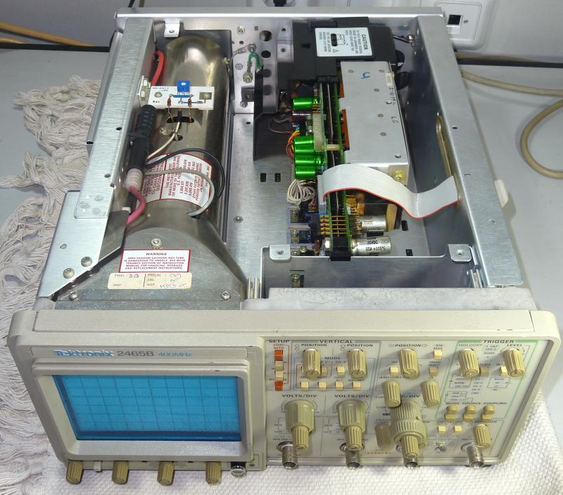
With front panel facing down, and main cover detached, the rear, top and left sides view. Top and left are covered by aluminium plates, these are HV and power sections.


With top cover opened. Wait !! It looks so empty and spacious ? Is that it ? No folks, these are just the crt tube and the main power supply only. The middle module has two separate pcbs, which are linear and switching part placed side by side isolated by a thick metal plate. Both supply the power for the whole scope. I guess they opted to place these noisy parts crt & psu in the middle isolated room to reduce hf noise.


The bottom and the right sides view, still standing vertically at it's face, look at the view, now we're talking.  :)
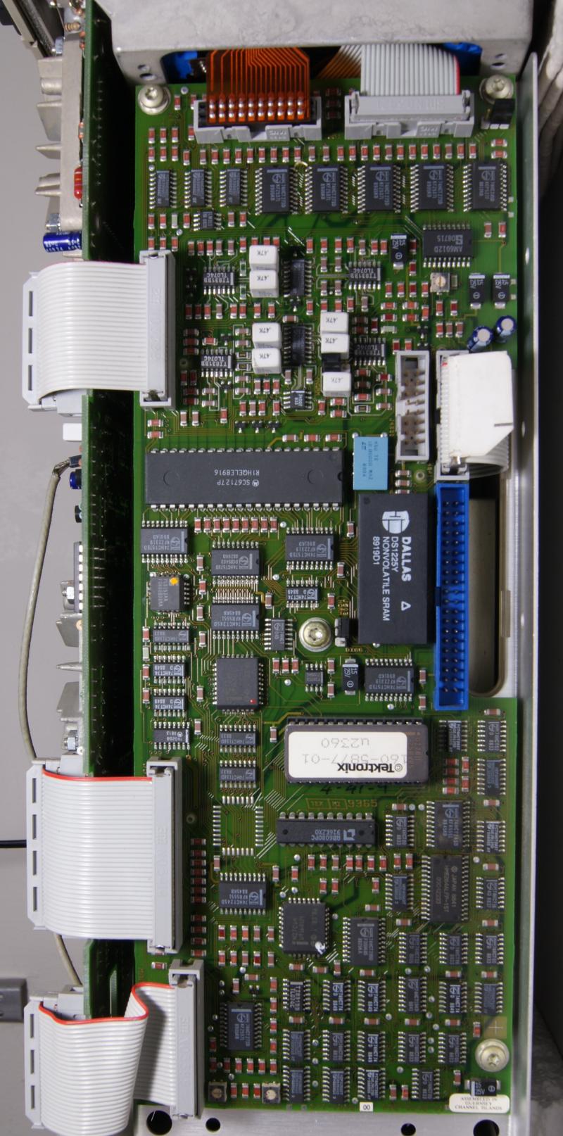
Bottom part is the main board for all analog stuffs there, while the left board is for the logic, cpu and control. What interesting about this view is, the big main board is using through hole components, while at the control board is using smd. Probably this was designed and made during the transitional period from through hole component to smd style.


The main A1 board, handles all analog stuffs here. The middle black zigzag stick is connected from the main power switch at the rear to the front panel power button. All components are using through hole style.


The A5 logic & control board, made it portrait view for better detail, almost all are using SMD components.


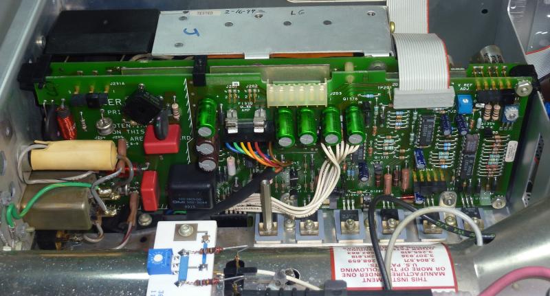
The left side view without the metal cover, high voltage crt power supply and the horizontal & vertical control board at the middle.


The power supply linear part and the main rectifier at the left side, while with switching part at the other side encased inside aluminium box. Few classic and popular to-220 linear regulator ICs are bolted at the bottom with thermal pad like LM 317, 7805.


The rear cooling fan without it's holding metal bracket, very noisy and it will be replaced with new & better fan. Also it's cables termination will be replaced with small 2 pins ordinary fan connectors for easy detaching it for cleaning and maintenance in the future, instead of permanently soldering them directly at the terminal (see inset).
Another interesting finding is the fan's date code 9605, it has the latest date compared to other components throughout the scope, looks like its 1996 or later made. Anyone know what year Tektronix stopped releasing the 24xx model ?


« Last Edit: March 23, 2018, 07:17:19 am by BravoV »
 
The following users thanked this post: sean0118, spec, salvagedcircuitry, qu1j0t3, wd5jfr

Offline BravoVTopic starter

  • Super Contributor
  • ***
  • Posts: 7547
  • Country: 00
  • +++ ATH1
Re: Tektronix 2465B oscilloscope teardown
« Reply #1 on: November 01, 2011, 07:02:52 am »
The Tek hybrid U800 IC part no 155-0241-02, that is really hard to find for the replacement but easily gets killed caused by overheating. This poor little ic is handling the whole horizontal part of the scope, and when powered on, it is very-very hot that almost burned my finger when touching the ic black body. The cooling path for heat dissipation is only through that metal tab at the IC, and goes through that tiny front bolt and rings as it's main heatsink, while the other bolt at the back is doing nothing for cooling, it just for holding this ic.  >:( 
Also its working at +87 volt and currently I'm still thinking on how to cool this IC better, maybe by attaching a small heatsink directly at that metal tab instead using heatsink at it's black body, but its not easy task because that bolt and the ic metal tab are not ground, they're -5 volt instead, damn !  :-\


Another corner, rusty nut, guess its time to replace it before it starting to eat through the bolt.  :-[ Also the bnc connection for the 4th channel and the 3rd at the background.


Same here, worry once the nut disintegrated by the rust, it will be become loosed by the heatsink tension, and finally cracked and burst or spread into small metal pieces across the board. Bad, really bad news if this happened.  >:(


Interesting spot, looks like that tiny inductor coil is hand made.  ;D  Definitely HF area, just too scared and afraid to touch or bump anything around here.  :o

« Last Edit: March 23, 2018, 07:16:02 am by BravoV »
 
The following users thanked this post: spec, Kirkhaan

Offline EEVblog

  • Administrator
  • *****
  • Posts: 37626
  • Country: au
    • EEVblog
Re: Tektronix 2465B oscilloscope teardown
« Reply #2 on: November 01, 2011, 08:52:44 am »
Awesome teardown, thanks for sharing!

Dave.
 
The following users thanked this post: Alex Nikitin

Offline BravoVTopic starter

  • Super Contributor
  • ***
  • Posts: 7547
  • Country: 00
  • +++ ATH1
Re: Tektronix 2465B oscilloscope teardown
« Reply #3 on: November 02, 2011, 02:34:14 am »
My pleasure Dave, glad you like it.

Offline Wartex

  • Frequent Contributor
  • **
  • Posts: 411
  • Country: ca
    • http://headsplosive.com
Re: Tektronix 2465B oscilloscope teardown
« Reply #4 on: November 03, 2011, 03:33:49 am »
Buy RAM chip heatsinks on eBay and use thermal epoxy to glue them right to the IC
 

Offline BravoVTopic starter

  • Super Contributor
  • ***
  • Posts: 7547
  • Country: 00
  • +++ ATH1
Re: Tektronix 2465B oscilloscope teardown
« Reply #5 on: November 04, 2011, 04:32:39 am »
Buy RAM chip heatsinks on eBay and use thermal epoxy to glue them right to the IC

Thanks, yes, I have few of them made from pure copper, its just I'm not quite happy since they're too small and also by cooling that U800 ic's substrate black body is not very effective compared to putting the heatsink directly at the metal tab.

Pics of the ram chip sinks on the ic, they're not permanently applied yet.


Other angle, as you can see, the front bolt and nut are useless, they're not touching any of the ic's body for cooling purpose, and whats the point of holding the IC when its already soldered at the pcb. I suspect originally these two bolts were designed to hold a custom shape heatsink for this scorching hot ic, looks like they never made it.   :-\


The vent holes at the bottom of the scope, these are for air intake, and the U800 is positioned at the upper left rectangular shaped vent holes.


Close up, the U800 is located right below here. From this vent holes position, its obvious that they're aware this location needs cooling, and should U800 have a proper heatsink, this is the right place for it.


I've been thinking to make two pieces of heatsinks, illustrated by two rectangles, the blue one is for the body, will be secured by the left nut and a steel wire (yellow marking) across both nuts, no problem with the height clearance for the upper MC3346P ic since U800 is higher by about few milimeters, this blue heatsink should not have any problem here. While the other heatsink (red rectangle) will be applied directly at the ic's metal tab  and secured by the right nut, this one is definitely better in dissipating the heat than the blue one. Clearance is pretty tight here, and must be precisely made, may be its time to visit local cnc shop, two options, either make it shorter or with the fat "L" shaped to avoid the bottom left vertically positioned ic.  Those few resistors and diodes in front of the metal tab are about 2 millimeters lower than the metal tab, so the blue heatsink base won't touch them at all if its fastened properly at the right nut.


Stay tune, I will be constantly update the progress here.
« Last Edit: March 23, 2018, 07:18:11 am by BravoV »
 
The following users thanked this post: spec

Offline rf-loop

  • Super Contributor
  • ***
  • Posts: 4059
  • Country: fi
  • Born in Finland with DLL21 in hand
Re: Tektronix 2465B oscilloscope teardown
« Reply #6 on: November 04, 2011, 12:19:17 pm »
Maybe you think that Tektronix EE's who design it are stupid?
They are not.

It works just perfect and thermal design is ok. There is NO any problem. Exept if someone take case off and use it without case. Also if FAN go bad it can go to thermal owerload.

I have study and inspect these oscilloscopes years (also I have no 3 pcs of these units in my lab for service and calibrate.

You can read Tektronix original full service and repair manual before you open oscilloscope if you design also power up it without case. It need use service enough airflow fan if need more time keep it running without case!

In the world you can find hundreds of defected Tektronix oscilloscopes just as burned hybrids and IC:s just becouse user do not care or "self learned service man" do not know how to handle these as professionals do who are specialised to make repair work with these nice scopes.

Before years they use different very expensive FAN in this scope but this version seems to be with this new fan what are in later manufactured units.

Before models have brushless hall controlled pulse driven motor what also have speed control as temperature change inside.

This airflow is calculated so that it is enough for cooling these circuits in full specified enviroment temperature range.
But it works only if scope have not much of dust inside and that air holes are open without dust.

U800 is very strong for high temperatures. It is also assembled to board just ok. Tektronix have long experience about use this circuit and if there is any big problem they have changed design after years of experience. This model is not one year design . 2465 models have been long time in production before your version and they have made many changes but U800 did not need make any changes for design. Not for circuit, not for mechanical and thermal design.
60 celsius is NOT hot. 90 celsius is not hot. 100 celsius is not hot. Also if uou know semi free air cooled chip. Thermal resistance between silicon and case is so that in free or small pressure air flow case temperature and silicon temperature have not big difference.

When case is closed and airflow work normally it keep it fully inside accepted temperature area.

If not believe you can put thermal sensor over chip and close case. Temp is more low than in free air temp.
same for these some maybe more sensitive hybrids.

Always if do example calibration  do it with service fan! Or do first adjustments what need open case and use service fan on the table. Then close case and let it warm half - one hour. Then continue these semiautomatic calibration steps.
Never touch any adjustments if have not needes test equipments. (and do not adjust these factory adjusted hand made looking coils without equipments and knowledge how to do.

In these units there are one problem Thiis NVRAM. They start be end of life.
Older version with separate soldered big lithium battery was more easy to handle.
If you loose this NVRAM data you loose all cal data and special data if scope have some options. (seems that you have not any options becous upside scope is nearly empty)

If you want change fan, kep special care its pressure/airflow data is perfect match. (it need know fan curve, noyt only free air volume. Best is change just same model. (littlebit can reduce noise if do floating assembly with thin and soft silicone isolating.
(this old model fan was more silent becouse there was no bearings noise connected directly to aluminium case.
I drive a LEC (low el. consumption) BEV car. Smoke exhaust pipes - go to museum. In Finland quite all electric power is made using nuclear, wind, solar and water.

Wises must compel the mad barbarians to stop their crimes against humanity. Where have the wises gone?
 

Offline slburris

  • Frequent Contributor
  • **
  • Posts: 542
  • Country: us
Re: Tektronix 2465B oscilloscope teardown
« Reply #7 on: November 06, 2011, 03:33:51 am »
I'd be less concerned about the U800 chip and more concerned about the 4 tantalum
surface mount capacitors on the A5 board.  They are known to leak with corrosive electrolyte
over time and can absolutely destroy the A5 board.

There's another thread on the forum about the A5 board, or you can look at this repair
guide someone put together:

http://www.condoraudio.com/wp-content/uploads/Projects/Tektronix-2465B-Oscilloscope-Restoration-Repair.pdf

Scott
 

Offline rf-loop

  • Super Contributor
  • ***
  • Posts: 4059
  • Country: fi
  • Born in Finland with DLL21 in hand
Re: Tektronix 2465B oscilloscope teardown
« Reply #8 on: November 06, 2011, 01:27:46 pm »
I'd be less concerned about the U800 chip and more concerned about the 4 tantalum
surface mount capacitors on the A5 board.
  They are known to leak with corrosive electrolyte
over time and can absolutely destroy the A5 board.


Also this issue is (maybe) related to manufacturing version (and  also where it have made).
If any suspect about possible leakage or fail. They need immediately take away, clean board and change new components.

And inside power unit are some famous weak electrolytics.

And also concern about this (mostly DALLAS) NVRAM. (this is designed lifetime!) Before they use EEROM and also RAM+Separate extremely good Lithium battery. (but reducing lifetime and costs...it is...what it is.)
I drive a LEC (low el. consumption) BEV car. Smoke exhaust pipes - go to museum. In Finland quite all electric power is made using nuclear, wind, solar and water.

Wises must compel the mad barbarians to stop their crimes against humanity. Where have the wises gone?
 

Offline wkb

  • Frequent Contributor
  • **
  • Posts: 900
  • Country: nl
Re: Tektronix 2465B oscilloscope teardown
« Reply #9 on: November 18, 2011, 06:26:46 pm »
This week I had the case off my 2465CTS.  In some aspects it is quite similar to the B version in this thread, but for example the digital controller PCB (wow... an 68B08, nice, I grew up with 6800 and 6809 ;-) is through-hole and not SMD.

It was suffering from a rattling fan, which had an interesting cause: it had been stored (at work) on its side on some shelf.  And apparantly some fat-fisted colleague of mine had dumped it on its side hard enough to push the handle lever into the case.  This caused to whole case to dent and slightly deform. >:( The aluminium of the case is really quite soft.  End result was that the fan (mine has a "rodent wheel" style fan) just touched the plastic back of the scope. Which rattled.  Sigh..

Interesting (...) side effect was that the outer shell would not slide off the frame.  I had to "crowbar" the  side of the case somewhat to get it off.  Once it was off, I could hammer (yes.. I had to use a hammer to fix a scope..) the dent out, which made the case slide back easily onto the frame.
 
Oh.. And I had to fit a new 10Mc Xtal on the digital controller PCB.  That got stuck behind the dented case and broke off.  ::)

Ah well, it is back to its glorious self again.  I got it years ago (for free, can't complain there!)

Wilko
 
The following users thanked this post: qu1j0t3

Offline larry42

  • Regular Contributor
  • *
  • Posts: 174
  • Country: 00
Re: Tektronix 2465B oscilloscope teardown
« Reply #10 on: November 19, 2011, 10:18:27 pm »
Maybe you think that Tektronix EE's who design it are stupid?
They are not.

It works just perfect and thermal design is ok. There is NO any problem. Exept if someone take case off and use it without case. Also if FAN go bad it can go to thermal owerload.

Well I've seen quite a few Service Notes for HP equipment, with small upgrades and improvements. Perhaps all the perfect engineers worked at Tek  ;)

And yes MTTF goes down with temperature, so if the chip is seriously hot, I would *consider* adding a heatsink, or a small extra fan, though with the caveat of thinking how the whole airflow though the system is arranged.

Good points on the fan replacement though.


If you have an animated GIF in your avatar or signature then I reserve the right to think you're a dolt.
 

Offline BravoVTopic starter

  • Super Contributor
  • ***
  • Posts: 7547
  • Country: 00
  • +++ ATH1
Re: Tektronix 2465B oscilloscope teardown
« Reply #11 on: November 20, 2011, 09:09:17 am »
Maybe you think that Tektronix EE's who design it are stupid?
They are not.

It works just perfect and thermal design is ok. There is NO any problem. Exept if someone take case off and use it without case. Also if FAN go bad it can go to thermal owerload.

Who is calling those Tek EEs stupid ? Suggesting you to read again since I believe English isn't your native by looking at your respond here, and I guess you're somehow a tek fanatic aren't you ? :D

I was just questioning why those bolts are there at the 1st place ? They're not even grounded to aid the thermal dissipation, and also why mechanically secure the ic which already soldered at the board ? If you have better explanation, I will glad to hear that.


I have study and inspect these oscilloscopes years (also I have no 3 pcs of these units in my lab for service and calibrate.

You can read Tektronix original full service and repair manual before you open oscilloscope if you design also power up it without case. It need use service enough airflow fan if need more time keep it running without case!

In the world you can find hundreds of defected Tektronix oscilloscopes just as burned hybrids and IC:s just becouse user do not care or "self learned service man" do not know how to handle these as professionals do who are specialised to make repair work with these nice scopes.

I had the user and tech manual both printed in A3 paper "BEFORE" I got this scope, was that your personal experience back there in the past ? ;)


60 celsius is NOT hot. 90 celsius is not hot. 100 celsius is not hot.

Don't know how to comment on this one, just recommend you to read many more semiconductor's datasheet on their max temp junction, and the effect of silicon's life when exposed at high temp like close to 100C, definitely is not good for their life.


When case is closed and airflow work normally it keep it fully inside accepted temperature area.

No argument here, the cooling effect will be only effective if with closed case, thats why those air vents are made for.


If not believe you can put thermal sensor over chip and close case. Temp is more low than in free air temp.
same for these some maybe more sensitive hybrids.

Surface temp will never be lower than ambient temp if using air cooling at "a non evaporating surface", its the basic law of thermodynamic, not sure where did you learn yours.


And also concern about this (mostly DALLAS) NVRAM. (this is designed lifetime!) Before they use EEROM and also RAM+Separate extremely good Lithium battery. (but reducing lifetime and costs...it is...what it is.)

This nvram is already in the work list, it will be desoldered and I will put a socket there to aid future replacement.

Oh yeah, don't worry, once pulled, the calibration data will be backed up 1st. ;)


I'd be less concerned about the U800 chip and more concerned about the 4 tantalum
surface mount capacitors on the A5 board.  They are known to leak with corrosive electrolyte
over time and can absolutely destroy the A5 board.

There's another thread on the forum about the A5 board, or you can look at this repair
guide someone put together:

http://www.condoraudio.com/wp-content/uploads/Projects/Tektronix-2465B-Oscilloscope-Restoration-Repair.pdf

Scott

Thanks Scott, yeah, already have that excellent document since the 1st day I got this scope. ;)

About this particular A5 model, its an early smd version which isn't plaque by the leaking caps like other late version, already got the confirmation at the TekScope yahoo group, but those caps will be checked too.


This week I had the case off my 2465CTS.  In some aspects it is quite similar to the B version in this thread, but for example the digital controller PCB (wow... an 68B08, nice, I grew up with 6800 and 6809 ;-) is through-hole and not SMD.

It was suffering from a rattling fan, which had an interesting cause: it had been stored (at work) on its side on some shelf.  And apparantly some fat-fisted colleague of mine had dumped it on its side hard enough to push the handle lever into the case.  This caused to whole case to dent and slightly deform. >:( The aluminium of the case is really quite soft.  End result was that the fan (mine has a "rodent wheel" style fan) just touched the plastic back of the scope. Which rattled.  Sigh..

Interesting (...) side effect was that the outer shell would not slide off the frame.  I had to "crowbar" the  side of the case somewhat to get it off.  Once it was off, I could hammer (yes.. I had to use a hammer to fix a scope..) the dent out, which made the case slide back easily onto the frame.
 
Oh.. And I had to fit a new 10Mc Xtal on the digital controller PCB.  That got stuck behind the dented case and broke off.  ::)

Ah well, it is back to its glorious self again.  I got it years ago (for free, can't complain there!)

Wilko

Bummer  :( , that poor thing, glad it works.


And yes MTTF goes down with temperature, so if the chip is seriously hot, I would *consider* adding a heatsink, or a small extra fan, though with the caveat of thinking how the whole airflow though the system is arranged.

Good points on the fan replacement though.

The whole airflow paths are quite clear from above pics, and the only exhaust is at the rear and the intakes are those vent holes scattered across the body which show those parts need fresh air.

Yep, replacing the fan is already in the list and will be using good fan like Sanyo Denki or similar.

Offline rf-loop

  • Super Contributor
  • ***
  • Posts: 4059
  • Country: fi
  • Born in Finland with DLL21 in hand
Re: Tektronix 2465B oscilloscope teardown
« Reply #12 on: November 20, 2011, 10:35:47 am »

If not believe you can put thermal sensor over chip and close case. Temp is more low than in free air temp.
same for these some maybe more sensitive hybrids.

Surface temp will never be lower than ambient temp if using air cooling at "a non evaporating surface", its the basic law of thermodynamic, not sure where did you learn yours.


There are so many misunderstoods in many places  becouse my poor english. I do not correct all, but this one I want try clarify what I mean (and it is extremely trivial case, only language is problem)

(of course there are three pathway for thermal power)

From silicon to out there is some thermal "resistance" between silicon and case outer surfaces including also pins.

If handle now only from case surface to air and leave these radiation and conducting away.

If case is open. There are only free air free convection what "flush" surface.
If case is closed and fan running. There is forced airflow directly to this componet surface. Amount of moving air is totally different and it moves more thermal power.  With case closed this component temperature is more low than with case open if there is not forced convection. This is reason why Tektronix rules that there need use service fan if use scope without case.
Of course becouse there is thermal resistance between case and silicon it also means that thermal current change means more thermal difference between surface and silicon if there is same thermal power generated.
If there is lower thermal current from case to enviroment then thermal difference between case surface and silicon is smaller (and hotter).
I have think these are so basic things that everyone can understand these without long explanation.

I have seen thermally damaged Tektronix hybrids. Sometimes reason is bad service man who forged scope runn without case and bottom down to table or even so that bottom of scope is upside but it is not very easy damaged. If fan stops there are no protection! And this is danger case. If case is closed as normally and fan fails. It may very easy overheat hybrids becouse there are anly low convection and radiation and conducting is not enough for cooling if it run long time. After hours there is very hot inside scope and some critical components may fail thermally.

Lack of thermal overheat protection is bad design.  How much it cost to watch fan or airflow (or temperature) nearly nothing if compare it to original price of this scope..

I have repaired these scopes and also years ago I have make many examinations about some design (and modifications) points inside these scopes for special use. Also this thermal question was one. And finally after many measurements and inspections I finally think, no need add heatsinks. (long time ago I was concerned just this same)
Yes it is true that component reliability littlebit go down if compare 60 celsius or nearly 100 celsisus.
But then need also remember what is product lifetime.  I have seen some this model what have >60000 hours and still working. 
Where are most common problems in these scopes (if keep out bad service damages).
(Fan (specially this older fan type), electrolytics, some resistors and diodes and capacitors specially in HV part and also input attenuators (mostly user mistakes but if unit have been in product testing and drived with computer there may also be worn attenuator unit). In older manufactured unit have different fan, it was very silent but also very fragile and hard work to change, and expensive!)
Units what I have in my lab have around 1500 - 4000hours.

If this scope need use in special enviroment then its thermal things need arrange different.
It need sometimes arrange separated closed inside air circulation and then  heat exchanger to outer cooling. (example in some explosive enviroment or if there is heavy dust or some other situation what is common example in military some other use)
I drive a LEC (low el. consumption) BEV car. Smoke exhaust pipes - go to museum. In Finland quite all electric power is made using nuclear, wind, solar and water.

Wises must compel the mad barbarians to stop their crimes against humanity. Where have the wises gone?
 

Offline BravoVTopic starter

  • Super Contributor
  • ***
  • Posts: 7547
  • Country: 00
  • +++ ATH1
Re: Tektronix 2465B oscilloscope teardown
« Reply #13 on: November 23, 2011, 03:29:26 am »
rf-loop

Thanks for the reminder, definitely will have a big house fan blowing at that the A1 board when running without the case, also usually it was never turned on more than 15 minutes when without it for brief checking and measuring like I did last time at the J119 header.

About the environment, don't worry, it will be used 99.99% of it's time at my bench table.

Btw, since I don't have enough time to work on this yet, any clue where to look for for my read out cursors posistion problem ? I mentioned this at my other thread here -> https://www.eevblog.com/forum/index.php?topic=5258.0 , currently I suspect the problem probably near the DAC ic and it's surrounding passive components at the A5 board.

About backing up the nvram, any suggestions or other tips ? My plan is to pull that dallas ic, do a backup externally and put it back but with ic socket installed. About the battery inside the nvram, I guess nothing we can do about it, its just a matter of waiting untill the internal battery ran out of power and have a replacement ready with the restored data.  :-\

If you have better solution, I'd love to hear that.
« Last Edit: November 23, 2011, 03:36:52 am by BravoV »
 

Offline rf-loop

  • Super Contributor
  • ***
  • Posts: 4059
  • Country: fi
  • Born in Finland with DLL21 in hand
Re: Tektronix 2465B oscilloscope teardown
« Reply #14 on: November 23, 2011, 06:07:33 am »
It looks that scope need service calibration.
If do adjustments it need follow _exactly_ Tektronix service manual. There are not words without meaning (even if it feels stupid..).

Also it need follow exatly this adjustment and calibration steps in the order what is  prescribed in manual, this order is important and manual tell what steps can do individually (there are not many these steps. First you start power unit voltages and reference adjustment and CRT itself adjustments (linearity etc things) and if then change these agen, oh well...do full service cal agen. So, follow manual, do not jump over any thing exept if manual tell specially that it can do, in other case it is prohibited..  (This manual need read so that what can do can clearly read on manual and if there do not read some thing is accepted then it is prohibited - just opposite than many other books - example law.)
Do NOT separate adjustments without knowing exactly if it interfere somewhere to some other thing (only some things can separately adjust without calibration procedure. Cursors need adjust inside cal procedure and in given order of steps.
What tell me that it need adj and cal. Cursosrs looks like fully out of order.  How is measurement accuracy?


How is this: "The power on message is "DIAGNSTIC. PUSH A/B TRIG TO EXIT", is this normal ?"

This is not normal!
This message tell that something is wrong (some rare cases it can do this once and reason may be "unknown" and in this situation it also can reset). 
Normally it do not appear without reason! If this appear, it can continue to normal scope  pushing a/b trig but now user  know that something is maybe wrong and it also need read as: "do not trust measurements before problem solved."

(exept if someone do manually "bad start" example keeping some button pressed during start up prosedure.)

But in older 2465  (B models with new SMD  HW I do not know)  it can also appear if oscilloscope shut down procedure fails (it may happend example if some capacitor is bad in this clever power unit and there is not enough power to run normal shut down procedure after switch off or loose mains electric...  This power up and power down "logic" can find in service manual. More serious case it may mean corrupted calibration or error in some circuit.

Becouse (in one your picture) cursors location is really bad it may tell that some calibration thing is not ok. (btw. now you have adjusted readings location without service calibration procedures - remember, they maybe now adjusted wrong and after (or better tell inside) service cal procedure you may need adjust also this agen).

Service cal must NOT START before sure that there is available all signals what need and just as they need be!
What ever step in procedure fails it can not continue AND id can not take back. There is no any "oops do not - take back" button after started cal prosedure (example vertical block) it need go from start to end and every step need just perfect cal signal from calibration generator and every step need adjust perfect becouse without this some other step may fail and it need do agen as long as it pass. (there is not "jump over" posibility -- oh yes there is is and result is what ever, maybe your cursors are from failed cal procedure if someone have not know what he is doing. Also in some things (some minor details) this manual is not very clear. 

Note also. Always before full calibration need inspect power unit voltages AND ripple. They need be well inside limits what service manual tell.  Selftest system give information what is wrong (what test number fails) but it do not know all. It do not know example if calibration data is wrong after some have done bad calibration.
This power up hours littlebit give feel that someone have reset system. If someone have done this, what other things he have done with oscilloscope in service mode.


« Last Edit: November 23, 2011, 08:03:27 am by rf-loop »
I drive a LEC (low el. consumption) BEV car. Smoke exhaust pipes - go to museum. In Finland quite all electric power is made using nuclear, wind, solar and water.

Wises must compel the mad barbarians to stop their crimes against humanity. Where have the wises gone?
 

Offline blueflash

  • Contributor
  • Posts: 20
  • Country: de
Re: Tektronix 2465B oscilloscope teardown
« Reply #15 on: November 23, 2011, 01:55:37 pm »
Although the U800 post is some days ago here my solution, which is similar to Yours but I used a bigger Heatsink with a hole for the screw to avoid electrical contact. Bevor mounting the heat sink with normal super glue I isolated the screw with a plastic tube.

Also I have a question if You would be so kind to tell me if I'm right.
When I got my Tek2465A I wondered about the missing illumination. So I decided to open the front panel where I expected the bulbs - but I found nothing (see last picture). Shouldn't there be the illumination lights?
 

Offline rf-loop

  • Super Contributor
  • ***
  • Posts: 4059
  • Country: fi
  • Born in Finland with DLL21 in hand
Re: Tektronix 2465B oscilloscope teardown
« Reply #16 on: November 23, 2011, 03:53:09 pm »
There need be illumination lamp board together with light distribution clear (partially painted) plastic. Also these lamps are very special small soldered lamps. On the main board is lamp driving  circuit. (also it is designed just like perfectionists do)

You have not service manual? If I remember right there is also full explanation about this light system.

Someone have take this light module. Sometimes peoples have get scopes where are missing hybrids..  (do not connect not compatible lamps to connector on the main board, it is possible destroy this lamp driver circuit and then in worst case you need change one IC on the main board)
« Last Edit: November 23, 2011, 03:56:43 pm by rf-loop »
I drive a LEC (low el. consumption) BEV car. Smoke exhaust pipes - go to museum. In Finland quite all electric power is made using nuclear, wind, solar and water.

Wises must compel the mad barbarians to stop their crimes against humanity. Where have the wises gone?
 

Offline blueflash

  • Contributor
  • Posts: 20
  • Country: de
Re: Tektronix 2465B oscilloscope teardown
« Reply #17 on: November 23, 2011, 04:09:29 pm »
Yes I got a service manual, but the part with the illumination is not illustrated so good. So I thought it is better to ask some knowing guys about it  :)

Am I right when I suppose that the red marked connector is the supply connector for the illumination?
 

Offline BravoVTopic starter

  • Super Contributor
  • ***
  • Posts: 7547
  • Country: 00
  • +++ ATH1
Re: Tektronix 2465B oscilloscope teardown
« Reply #18 on: November 24, 2011, 03:21:16 am »
It looks that scope need service calibration.
If do adjustments it need follow _exactly_ Tektronix service manual. There are not words without meaning (even if it feels stupid..).
That is what I'm afraid of, cause I don't have enough supporting tools to do that, while sending it to certified calibrator is not an option since its way too expensive, the cost of certification might be more than a new 200Mhz china made digital scope.  :'(
While the price of this thing I bought is less than $300.


How is measurement accuracy?

So far I only tested with against the Tek 2901 time mark generator and these are the results :


(btw. now you have adjusted readings location without service calibration procedures - remember, they maybe now adjusted wrong and after (or better tell inside) service cal procedure you may need adjust also this agen).
Nope, checked with service manual, the adjustment I've made at R2918 to fix the readout vertical position is not part of the calibration procedure that will be stored as calibration data, check again your service manual.

For sure I will not touch or start any calibration until I have the adequate supporting tools to do that and aware that this must be followed step by step exactly as the manual instructed. Btw the service manual it self has flaw as pointed one of the member at tekscope group that there is an additional steps to be done to complete it.

Since you said you've done many calibrations on these scope before, what kind of tools you have there to help your job ?
 
The following users thanked this post: slbender

Offline BravoVTopic starter

  • Super Contributor
  • ***
  • Posts: 7547
  • Country: 00
  • +++ ATH1
Re: Tektronix 2465B oscilloscope teardown
« Reply #19 on: November 24, 2011, 03:28:36 am »
Although the U800 post is some days ago here my solution, which is similar to Yours but I used a bigger Heatsink with a hole for the screw to avoid electrical contact. Bevor mounting the heat sink with normal super glue I isolated the screw with a plastic tube.

Thanks for sharing that, nice to see how other 2465x owner cooled their U800.

Also I have a question if You would be so kind to tell me if I'm right.
When I got my Tek2465A I wondered about the missing illumination. So I decided to open the front panel where I expected the bulbs - but I found nothing (see last picture). Shouldn't there be the illumination lights?

Yes I got a service manual, but the part with the illumination is not illustrated so good. So I thought it is better to ask some knowing guys about it  :)

Am I right when I suppose that the red marked connector is the supply connector for the illumination?

Although I haven't look into my front panel at the illumination part as yours, I believe yours are gone, sorry to hear that.  :-\

Looks like the previous owner pulled it out, anyway, there are few ebay seller are offering this part for few dollars.

Attached below of my cable connection at J181 connector and the picture from the service manual, apparently yours are missing the 11,12 and 15 parts.


Offline rf-loop

  • Super Contributor
  • ***
  • Posts: 4059
  • Country: fi
  • Born in Finland with DLL21 in hand
Re: Tektronix 2465B oscilloscope teardown
« Reply #20 on: November 24, 2011, 06:32:47 am »


(btw. now you have adjusted readings location without service calibration procedures - remember, they maybe now adjusted wrong and after (or better tell inside) service cal procedure you may need adjust also this agen).
Nope, checked with service manual, the adjustment I've made at R2918 to fix the readout vertical position is not part of the calibration procedure that will be stored as calibration data, check again your service manual.


My thinking was: Now if you do full service calibration it may affect some things and maybe also these readings position slightly change and need maybe also agen adjust.  All adjustements are not directly related each others but it is better to follow service cal steps in order so work is more easy and do not need go back agen. But of course something can adjust.
But I see one your picture and readings was extremely bad position before your adjustments. How they have changed? This kind of change is not normal exept some component fail or someone have done bad adjustments.
How are vertical cursors and horizontal cursors if you measure some exactly known signal. Also how horizontal cursors accuracy if measure things together with B timebase.
Cursors horizontal accuracy is best in -4 to +4div from centerline. If visually signal trace is in good accuracy and if cursors display enough accurate it do not of course need any cal.  In normal use this check is enough.

If need real  calibration/ calibration with data (and traceable)  then all need measure accurate and write values to record and if need (limits breaks) then do full cal and agen do cal check data record. Normal user do not have this.

-------

I have tektronix calibration generators. Example CG5011 and CG5001.  Then also fast rising pulse generator tektronix 284. And of course oscilloscope(s) what can use inside cal procedure. (it need external and good analog oscilloscope or so good digital oscilloscope what I have never own. It can not do with Hantek, Owon, and of course nothing with Rigol) 
And other tools. Also enough reliable DVM for reference adjustments.  But this level and timing calibration signals is most important. Then specially timebase(s) calibration need this external oscilloscope. There is nice adjustment method inside this 2465 FW)
« Last Edit: November 24, 2011, 11:36:13 am by rf-loop »
I drive a LEC (low el. consumption) BEV car. Smoke exhaust pipes - go to museum. In Finland quite all electric power is made using nuclear, wind, solar and water.

Wises must compel the mad barbarians to stop their crimes against humanity. Where have the wises gone?
 

Offline blueflash

  • Contributor
  • Posts: 20
  • Country: de
Re: Tektronix 2465B oscilloscope teardown
« Reply #21 on: November 24, 2011, 10:40:14 am »
Thanks for the reply, that confirms my speculation about the missing illu.

Btw, if someone has problems with the eproms on the digital board loosing their "mind" - I read them out and can share the files if needed. I guess they are different for the models 2465/2465A/2465B (my model is 2465A). 
 

Offline BravoVTopic starter

  • Super Contributor
  • ***
  • Posts: 7547
  • Country: 00
  • +++ ATH1
Re: Tektronix 2465B oscilloscope teardown
« Reply #22 on: November 25, 2011, 03:51:39 am »
Thanks for the reply, that confirms my speculation about the missing illu.

Btw, if someone has problems with the eproms on the digital board loosing their "mind" - I read them out and can share the files if needed. I guess they are different for the models 2465/2465A/2465B (my model is 2465A).

No problemo, my pleasure and if you need other angles shot to compare with mine on other parts that you suspect that they're missing or tampered, just ask, I will try my best, got tons of close up shots here. ;)

Interesting offer, I take it although mine is 2465B, who knows someday I will need it even I'm pretty sure they're different.

Btw, is that 2465A has the same A5 board as mine that has the Dallas nvram ? or its using the older model with external lithium battery ?

Offline blueflash

  • Contributor
  • Posts: 20
  • Country: de
Re: Tektronix 2465B oscilloscope teardown
« Reply #23 on: November 25, 2011, 11:18:42 am »
Seems to be the older model with lithium battery.

Find attached the binaries of the EPROMs in the hope that it will help somebody someday. I heard sometimes that EPROMS may loose their memory after 10 or more years - especialy if they work at higher temperature. So I deicided to save the EPROMs of my devices.


Offline slburris

  • Frequent Contributor
  • **
  • Posts: 542
  • Country: us
Re: Tektronix 2465B oscilloscope teardown
« Reply #24 on: December 20, 2011, 06:06:57 pm »
Note that there's a lot of Tektronix firmware archived here:

ftp://ftp.bluefeathertech.com/electronics/testgear/Tektronix/firmware

Scott


Share me

Digg  Facebook  SlashDot  Delicious  Technorati  Twitter  Google  Yahoo
Smf