You need a proper PCB with SMT components. The way this circuit is built is asking for problems.
For 2.2-2.5GHz I agree. There are an awful lot of antennas in that picture.
I would also recommend a bandpass filter on the front end too to band limit what's going into the log amp. If you can narrow it down a bit further, to 100MHz or so, you could use an off the shelf saw filter.
Also forget BNC at 2.4GHz, use SMA. I use edge mounted SMAs very extensively for these sorts of prototypes, worth having a bag of them handy, you can get them on eBay reasonably cheaply.
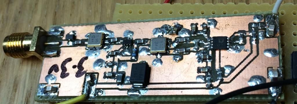
Edit: Here's a circuit I made up about 18 months ago with an AD8313, for 1.09GHz, with two cascaded SAW filters and a preamp (this is not my circuit design, but the board and schematic capture are mine, attached). The second saw filter and preamp may be unnecessary for your application, this design is for over-the-air secondary radar reception. As you can see, the intra-component spacing for the RF path is about 1/10th", sometimes smaller, basically as short as I can get it with a reasonable DRC check. Bottom of the board is solid copper ground plane, and it's 1.6mm FR4. To be picky, I'd use a thinner dielectric to make an effort to maintain impedance, but it works well enough as it is. The diode on the picture but not on the schematic is to save me from myself, a rev polarity diode. For 2.4GHz, I'd be going to 0402 parts too, these were 0603.