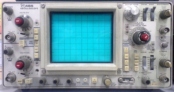
Hello Everyone... I'm just starting out (but I'm SUPER excited about electronics!) and I heard on a web form that beginners should get an analog oscilloscope for their first scope so I picked up a Tek 465 for a really good deal. None of the knobs are missing! Here's a picture!
Anyways... All this math channel talk sounds really interesting, but I'm having a really hard time trying to figure out how to get my Tek 456 math functions to work.
Can someone please help me find the FFT button on my scope.. I've looked everywhere!!
Thanks!
I don't know quite why earlier posters thought it was funny to tell you a lot of nonsense, but here is the answer to your question.
On Analog Oscilloscopes, the maths functions are limited to "A-B" & "A+B" , where "A" & "B" denote two vertical channels.
This was done in hardware, so the more complex mathematical functions would have been prohibitively costly to implement.
With DSOs, all such functions can be done in firmware, in most cases, or loaded as software in some others.
FFT also is something relatively easy to do in DSOs, & extremely difficult to do in Analog 'scopes.for the same reason.
The FFT function in DSOs can be good, or quite poor, depending upon the implementation.
A real Spectrum Analyser still offers superior performance.
Some Analog 'scopes had SA "plugins"or adaptors as accessories, like the 4401 adaptor for your 465.


