Author Topic: Resize a STL File For Me  (Read 9738 times)

0 Members and 1 Guest are viewing this topic.

Offline MarkF

  • Super Contributor
  • ***
  • Posts: 2550
  • Country: us
Re: Resize a STL File For Me
« Reply #100 on: February 14, 2024, 06:02:31 pm »
Here are the Knob2 files for both the old 0.16 and the current 0.21.2 versions of FreeCAD.
These files have the dimensions for the D-shaft of 6.4mm diameter hole and 4.9mm flat
used in the last STL file I posted.
 

Online bostonmanTopic starter

  • Super Contributor
  • ***
  • Posts: 1794
  • Country: us
Re: Resize a STL File For Me
« Reply #101 on: February 14, 2024, 07:00:09 pm »
Great, thanks again!

Hopefully your design will help others too. If all it needs is a few tweaks to resize the overall knob, then this could be quite useful to others since test equipment is prone to broken knobs.

This has certainly opened my eyes to being reminded of becoming more knowledgeable with 3D designs. What a great time we live in that helpful people can create something in one part of the country/world, send the file, and the end user can just print the part to fix their issue.
 

Online bostonmanTopic starter

  • Super Contributor
  • ***
  • Posts: 1794
  • Country: us
Re: Resize a STL File For Me
« Reply #102 on: March 28, 2024, 02:55:46 am »
MarkF,

I have a few questions but not sure if I'm going to ask them correctly. Since you created the 6mm shaft knob, referencing it may be the best way to ask my questions.

Basically I'm trying to expand my 3D modeling knowledge and using FreeCAD to do so. Much like other 3D models I've seen, you have several separate sections such as: Revolution, Sketch, Pad001, Sketch001, Sketch002, etc...

As I click on different sections of the knob, specific sections get highlighted. I'm curious why or when is it appropriate to create a separate sub part/section.

To be more specific, before I thought if I were to create a 3D model of a car, I'd create the body, engine, tires, etc... as individual pieces. What you seemed to do is create many separate pieces within just one part.

Recently I downloaded the STEP file for a BNC connector for reasons not worth getting into. The STEP file had numerous individual pieces all within just the BNC. So again, I'm wondering how/when this is done.

With your knob, as I click on each section, it gives me the impression numerous separate pieces were used, but I can't follow it.

Also, although I have several lingering questions I'm trying to work through with FreeCAD, one basic general question is say I wanted to add something like a plate for the knob to sit on. Let's say I wanted to make it a trophy. How do I make the plate "touching" the knob so it's all one piece that gets printed? I think this is called a face, but I haven't found any tutorials that explain this.
« Last Edit: March 28, 2024, 02:57:38 am by bostonman »
 

Offline MarkF

  • Super Contributor
  • ***
  • Posts: 2550
  • Country: us
Re: Resize a STL File For Me
« Reply #103 on: March 28, 2024, 01:47:46 pm »
I guess my first question is which version of FreeCAD are you referring to?

In the old version (discussed earlier), it is not possible to create multiple parts.

As far as order is concerned, in many times you don't have a lot of choice.
Certain operations depend of previous ones.  For example, you can't cut a hole in a part
you haven't created.  If you wanted to add a plate to the knob as you suggest, you would
just create a new sketch to the last operation in order to create a pad or perform a
revolution operation.  In the newer versions of FreeCAD, you can create multiple bodies
to build up your model.

The order you create the model depends a lot on what you're modelling.  Most likely, you
will build the model from the inside out.  Mainly you create a sketch, use that sketch
to perform a further operation (pad, revolve, cut), and then a boolean operation in some cases.
After you're comfortable, you can move to the 'draft' workbench to add text.  More advanced
operations to learn are the loft and pipes to create a curved surface or to draw a sketch along
a path.  In the beginning, you try to do things a certain way and find out you can't get from
point A to point B and will need to do it differently.  Especially in the older versions.
I do most of my modelling in the 'part design' workbench building sketch upon sketch.
Think of a sketch as the shape of the tool you will use to draw with.

I can suggest a few YouTube channels:
  - https://www.youtube.com/playlist?list=PL7eiW2bt21YU6QEbly78kUgQCNEiDUwSH
  - https://www.youtube.com/playlist?list=PLWuyJLVUNtc0UszswD0oD5q4VeWTrK7JC

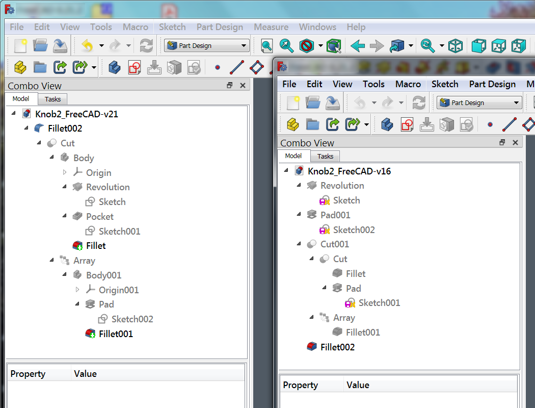
Perhaps a photo of the two versions of FreeCAD:
  2087690-0
 

Online bostonmanTopic starter

  • Super Contributor
  • ***
  • Posts: 1794
  • Country: us
Re: Resize a STL File For Me
« Reply #104 on: April 07, 2024, 01:58:30 pm »
I watched some of those videos and will watch more as time goes on.

Recently I wanted to make a shape (using Free CAD v0.16) and attached a general sketch. In order to make this, I made the outside circle 50mm, the next one in 40mm, and then used pad to give it height.

After I added another shape making the circle 40mm (so it meets the previous circle), the inside one 15mm, and used pad to bring the height slightly less than the other shape.

Although the object came out correctly, I sense this isn't the correct way to do it; nor does the slicing software seem happy because it's doing some funky stuff with the layers. If I try adding a chamfer to the outside (higher raised) circle, the slicing software seems to not see it (even though I exported all the associated stuff in the left side panel).

I'm not asking for someone to create this, but only asking whether this needs to be done as two sketches, add something, or whatever, so I can learn. Keep in mind, I'm still trying to wrap my head around creating parts beyond a simple 2D sketch.

Also, I've yet to find why FreeCAD has a robot workbench. Does anyone know the reason for this? Although it's cool, I don't know what purpose it serves.
 

Offline MarkF

  • Super Contributor
  • ***
  • Posts: 2550
  • Country: us
Re: Resize a STL File For Me
« Reply #105 on: April 07, 2024, 02:19:32 pm »
I think the problem is that the inner disk and the outer ring are being seen as two different parts.
(i.e. the 40mm intersection is exact between the two.)
FreeCAD has some problems with exact edges like that.
You can try changing the inner disk to have its diameter equal to the diameter of the ring (i.e. 50mm or 40.001mm).

A better way of creating the part may be to create a disk with 50mm diameter with 20mm height and 15mm hole.
Then cut out the 40mm x 10mm hole from the inside.
 

Online bostonmanTopic starter

  • Super Contributor
  • ***
  • Posts: 1794
  • Country: us
Re: Resize a STL File For Me
« Reply #106 on: April 07, 2024, 02:53:32 pm »
Quote
I think the problem is that the inner disk and the outer ring are being seen as two different parts.

From how I interpreted the image/stl, this was my thought too.

Quote
A better way of creating the part may be to create a disk with 50mm diameter with 20mm height and 15mm hole.
Then cut out the 40mm x 10mm hole from the inside.

I'll try this method tonight.
 

Offline MarkF

  • Super Contributor
  • ***
  • Posts: 2550
  • Country: us
Re: Resize a STL File For Me
« Reply #107 on: April 07, 2024, 03:30:40 pm »
I just recreated the part as you described including the chamfer without any issues in version 21.2
This might just be something that works better in the newer version of FreeCAD.

Like I said a while back:  "Sometimes you just have to tinker with how you create a part to make it work."


Also, I was able to create a STL and slice your zip file part without issue.
This also might be how the new version of FreeCAD creates STL files.


FYI: I'm using the latest PrusaSlicer on Windows 7.
I left Cura in the dust since they don't want to support Windows 7 any longer. 
Also, I hated the way you have to control Cura's view angle on a laptop without a mouse.
I wish both slicers would adopt FreeCAD's SHIFT/ALT pan and rotate control.
 

Online bostonmanTopic starter

  • Super Contributor
  • ***
  • Posts: 1794
  • Country: us
Re: Resize a STL File For Me
« Reply #108 on: April 07, 2024, 03:56:30 pm »
I have a Win7 laptop as well that I can install V21.2 on.

Quote
Like I said a while back:  "Sometimes you just have to tinker with how you create a part to make it work."

I fully agree and it's why I tried making the second circle equal to the diameter of the other circle. In my mind, it didn't make sense because, as you stated, and I assumed, it's making two separate parts that "touch" each other rather than uniform.

My point is that I did spend time tinkering. In my slicing software, one view didn't show the chamfer, but the 3D view did, however, it also showed support material embedded in the inner circle; this is when it being wrong was obvious.

I attempted to print the part for fun, but it came out looking worse than expected.
 

Online bostonmanTopic starter

  • Super Contributor
  • ***
  • Posts: 1794
  • Country: us
Re: Resize a STL File For Me
« Reply #109 on: April 18, 2024, 03:51:25 am »
I'm uncertain whether I should start a new thread.

Periodically I tinker with FreeCAD (0.16) and trying to learn all the options. One option is the 'groove' option and I watched a video ().

Following the video to a degree, I managed to create a groove, but I don't understand what I actually did.

At approx. 2:40min into the video he creates a rectangle on top of the cylinder. First he created a cylinder, created a rectangle on top (for some reason), created the groove pattern, and then used that to make a 360 degree groove around the cylinder.

How is this different than using rotation?

Why was the rectangle needed?

Due to errors in my attempts, does the groove pattern need to be spaced a specific distance from the vertical axis?

It got somewhat confusing why another sketch was created, then pad was selected, another sketch, etc...  I managed to create a funky looking groove in my cylinder, but don't quite get the reasons for the steps including the last three or four steps after the groove was completed (and the rectangle was removed).
 

Offline MarkF

  • Super Contributor
  • ***
  • Posts: 2550
  • Country: us
Re: Resize a STL File For Me
« Reply #110 on: April 18, 2024, 12:37:58 pm »
How is this different than using rotation?
- The 'groove' tool basically does a rotation and then a cut.  It's doing multiple operations with one tool.

Why was the rectangle needed?
- The little rectangle on the top was to provide a reference face along the X-Z axis for the groove tool to operate upon.

Does the groove pattern need to be spaced a specific distance from the vertical axis?
- In this example, the 'groove' pattern will be revolved around the Z-axis.  So, you can't have any part of the pattern on the negative X-axis.  If you place part of the pattern on the Z-axis, the 'groove' tool will cut the object in half.

It got somewhat confusing why another sketch was created, then pad was selected, another sketch, etc...
- As mentioned above, the 2nd sketch and pad was to provide a reference plane for the 'groove' tool.  In the newer versions of FreeCAD, I didn't need to create that 2nd sketch.  I was able to reference the X-Z plane directly.  You have a more ways of creating reference planes in the newer versions.
 

Online bostonmanTopic starter

  • Super Contributor
  • ***
  • Posts: 1794
  • Country: us
Re: Resize a STL File For Me
« Reply #111 on: April 19, 2024, 02:53:52 am »
Sorry, I used the term 'rotation' and meant 'revolution' (located in the design drop down menu). At one point I tinkered with revolution, and, when I accomplished a groove pattern, wondered if a difference exists.

Quote
I was able to reference the X-Z plane directly.  You have a more ways of creating reference planes in the newer versions.

I assumed the groove "reference" was the vertical part of the groove pattern, however, if this is an outdated method and revised in later versions, no sense pondering on the topic.
 

Offline MarkF

  • Super Contributor
  • ***
  • Posts: 2550
  • Country: us
Re: Resize a STL File For Me
« Reply #112 on: April 19, 2024, 12:39:22 pm »
I don't know if there is a question there...

FreeCAD 0.16 was released in April 2016.
While it is terribly out of date, you still need to understand how
that version of the program works in order to be productive.
It wouldn't be important to others, but it's worth your time.

Let me pose a modification to the exercise in the video.
How would you rotate the groove pattern around the X-axis instead of the Z-axis?
I haven't tried this.
 

Online bostonmanTopic starter

  • Super Contributor
  • ***
  • Posts: 1794
  • Country: us
Re: Resize a STL File For Me
« Reply #113 on: April 19, 2024, 01:39:53 pm »
Quote
How would you rotate the groove pattern around the X-axis instead of the Z-axis?
I haven't tried this.

That's a good question and I'm uncertain.

While I grasp some of the concepts, I don't necessarily understand the steps. At the end of the video he adds a sketch to the face of the rectangle, does something else, and makes it "vanish". Not sure why the rectangle sketch just can't be deleted at that point, however, my point is that it's a step I can easily follow but don't understand.

Per your question, a twist is: after making a cylinder, if I want to attach a square perpendicular to the cylinder, how do I attach the face? Each time I tried this last night, the square (or rectangle) would attach itself to the center of the x-axis.
 

Offline MarkF

  • Super Contributor
  • ***
  • Posts: 2550
  • Country: us
Re: Resize a STL File For Me
« Reply #114 on: April 19, 2024, 04:13:51 pm »
Not sure that I've figured out how version 0.16 is working.

However if you draw a cylinder around the z-axis as in the video.

Select the top cylinder end face as the reference to create the reference sketch (as the video).
Draw a square with two edges on each of the x-axis and y-axis in the positive direction.
Pad the reference square to a cube.
(Basically, make the little rectangle and pad in the video into a cube for more clarity.)

Now you have a cube which you can use to reference any of the faces in order
to create your cutting pattern.  The revolve then allows you to rotate the cutting pattern
in either the horizontal or vertical directions.

Clear as mud???   For me too.


To answer an earlier question, you can't delete this reference cube because that would
break the draw path used to update the part.  You can only add a cut of the cube at the
trailing end of the operations.
« Last Edit: April 19, 2024, 04:22:12 pm by MarkF »
 

Online bostonmanTopic starter

  • Super Contributor
  • ***
  • Posts: 1794
  • Country: us
Re: Resize a STL File For Me
« Reply #115 on: April 19, 2024, 04:56:01 pm »
I’ll tinker with it over the weekend.

Just for the record, I’m not necessarily trying to perfect learning FreeCAD, but more about trying to understand the foundation of it so I can understand what I’m actually looking at when I create a model. The goal and obvious method is to use the latest version rather than learn outdated tools, but I like learning the foundation rather than just steps.


Share me

Digg  Facebook  SlashDot  Delicious  Technorati  Twitter  Google  Yahoo
Smf