Do you know why I keep asking? Because if you answer it correctly then you'll admit that KVL works in Lewin's circuit, which is the topic of this forum.
Ah, yes. The ultimate killer question.
So, see if you can calculate VAD and then measure VAD and they match... So start by calculating VAD first, then we can talk.
Oh, for Fuchs' sakes!
1) What is the calculated voltage between nodes A and D, VAD, in Lewin's circuit? It.
Depends.
On.
The.
Path.
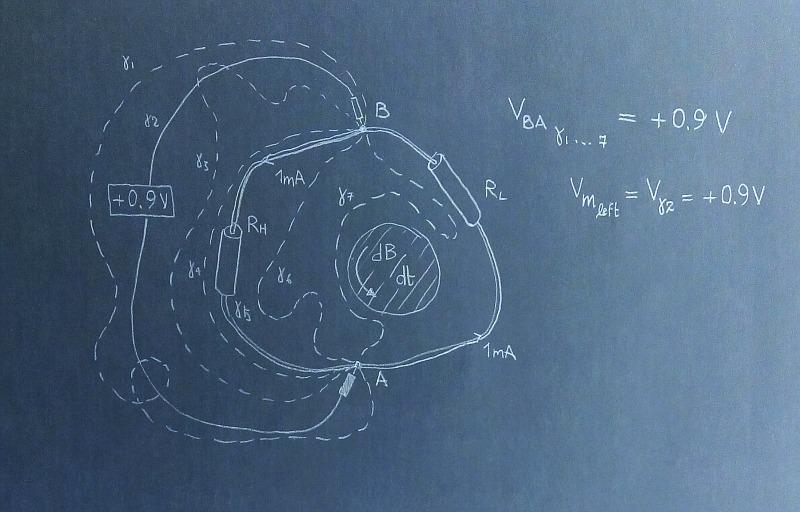
Here are a few paths for which VAD, which I call VBA, has the value +0.9V.
Among this paths there are the left circuit branch and the path composed by probes and left voltmeter.
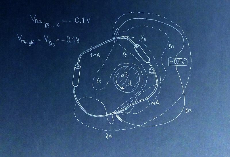
And here are a few paths for which VAD, which I call VBA, assumes the value -0.1V.
Among these paths there are the right circuit branch and the path composed by probes and right voltmeter.
Mind you, my hand was uncertain and I draw a wobbly Lewin circuit, even off center with respect to the EMF generating coil. Still, I can put values on all those voltages, including the voltages across the resistors themselves.
Can you do the same with your KVL-obeying voltages?
Please, do so. Provide the voltages
across the resistors and
across the probes. Or shut up.
For paths cutting the variable magnetic field region, I can get all values comprised between +0.9V and -0.1V including 0V, 0.5V and 0.4V (what you would call the 'true' voltage in the circular, symmetric and axially aligned Lewin ring - but is it the same in this irregular off-center circuit? You tell me. Or shut up).
2) Is it the voltage VAD the same as the voltages measure by the voltmeters in Lewin's circuit?Voltage VBA for the left branch of the circuit is the same as the voltage measured by the left voltmeter.
It is also the same as the voltages along paths gamma 1 to 7.
Voltage VBA for the right branch of the circuit is the same as the voltage measured by the right voltmeter.
It is also the same as the voltages along paths gamma 8 to 14.
Here is the total electric field inside the circuit. I am also giving the dimensions of the asymmetric ring. Let's say the inner solenoid perimeter is tangent to the straight line joining A and B and has a diameter of 2 cm. Or, if you prefer, draw the circuit to scale and put your own length.
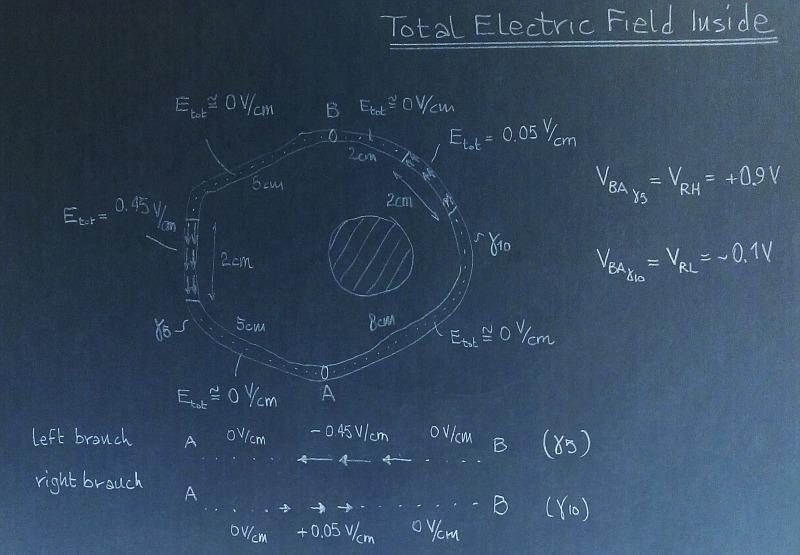
If you feel the total field inside is wrong, by all means provide your solution. Or shut up.
And here is how I compute the voltages along the two branches of circuit from path integrals
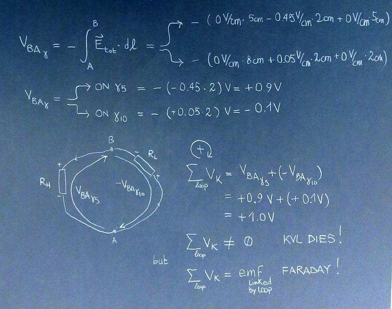
I have thrown in, for good measure, the reason why people say KVL no longer works in this circuit: if you sum all voltages along the closed path (be they drops or localized EMFs) you end up with a nonzero total. The total is the EMF linked by the closed path itself. But let's
NOT talk about that. Let's focus on the voltages and on how you compute the voltages across the resistors and across the probes for this asymmetric and off-center circuit.
In my world the arcs of conductor and the probes obey Ohm's law and therefore develop no voltage. Put your numbers in, now.
Incidentally, if the segment AB is tangent to the solenoid, VBA along the straight line joining A and B will be 0.9V, in this circuit.
3) If you are given the measured voltage of the voltmeter as well a the location of the voltmeter's probes in Lewin's circuit, can you determine the correct value of VAD?Yes. But remember:
in my world the voltage depends on the path. So I will be able to tell you what the voltmeter will read and how it relates with the voltages along the left and the right branches of the circuits.
4) If the answer to 3) is yes, how would you do it? By applying Faraday's law when my loops include the variable magnetic region, and by applying KVL when they do not.
Now, please, tell me what are the values of the voltages across the resistors and the probes.
We all know we agree on what the voltmeters will measure. Show us how you compute the voltages across the probes and resistors in this asymmetric and off center configuration. Copy the profile of one circuit and report back
when you have the results.
EDIT: added missing bold face (pun intended).


