Author Topic: #562 – Electroboom!  (Read 107963 times)

0 Members and 1 Guest are viewing this topic.

Offline Sredni

  • Frequent Contributor
  • **
  • Posts: 686
  • Country: aq
Re: #562 – Electroboom!
« Reply #525 on: November 30, 2021, 04:46:58 pm »
Jesse, Jesse...
I did answer your question related to the previous circuit. I also pointed out that the answer was in the top right corner of my images for Lumped and Not lumped circuits. You seem to think that, because lumpABLE circuits exists and as such can be made lumpED by choosing a suitable circuit path, then there cannot be alternatives.
There are alternatives:

Alternative 1: the lumpABLE circuit itself. You choose another circuit path (for the same set of components and connecting wires!) that does include the variable magnetic region. Your system has now path dependent voltage and is NOT lumped.
Alternative 2: there are other circuits in the universe that are UNlumpable. Lewin's ring is one example.
But I'm asking a yes or no question, and you're saying everything other than yes or no.

Here's the picture I was talking about:


It's literally titled: "KVL-works-if-I-leave-out-the-magnetic-region.jpg"
Does the ".jpg" confuse you? Or is it the dashes?
If you look at the top right corner, it says: "KVL works here".
What part of "KVL works here" you do not understand? "KVL"? "works"? "here"?

I hope it is clear that if you choose to look at a lumpABLE circuit as a lumpED circuit, then KVL works.
The problem is that, even if KVL works there, it does not mean that KVL works for all other circuits in magnetoquasistatic conditions. I just need one example to prove it doesn't. And Lewin's ring is such an example.

You know, the circuit for which you are not able to define a circuit path that does not contain the variable magnetic region.

I am pretty sure that one of your many problems is that you don't understand the difference between the physical system (usually called "the circuit") and the actual circuit path. The one I keep talking about... you know when talking about lumped circutis with inductors I say "instead of following the coil filament we jump at the terminals" or something like that?

Quote
Quote
And the fact that you cannot come up with an answer to my question is proof that you are not able to lump it. Don't feel bad. Nobody can lump that without incurring in self-contradiction. It's not your fault. It's the circuit that's drawn like that.
No, it means you're not explaining your question. You're asking me to draw something you're picturing in your mind. I did what I thought you wanted - I illustrated how to unambiguously physically measure the voltage across the half-turns in Lewin's experiment

So, let's see.
I ask you to draw in green the circuit path that, if the circuit is lumpable, must not contain the shaded dB/dt region, and you draw the path you have to put the probes to measure something I did not even mentioned in my question?
Nice try.

Wanna try again?

Quote
Quote

Now you try to shift the attention on yet another lumpABLE circuit, putting your voltmeters in a manner that imply you prefer to use a circuit path that makes it lumpED. Yes, as a lumpABLE circuit, it can be lumpED. But this does not imply that

1. it can also be seen as NOT lumped, by choosing a different circuit path (same components, same wires, same transformer!)
2. there are other circuits out there that are UNlumpable

I really cannot be more clear than this. Try some vitamins, maybe?
My question is a simple yes or no question. Either the volt meters will sum to zero or they won't. Or maybe you think they might some days depending on the phase of the moon.

If you place your voltmeters all in the same simply connected region that does not include the variable dB/dt region, then yes of course KVL will work. It's written in the top right corner of the picture I have posted more then a week ago. You still have to understand that?

Quote
Quote
But here's the deal: if you put the numerical values of the voltages read by your voltmeters, I will show you the NOT lumped version of your circuit, so that you will avoid posting it again in the same way you are avoiding my question on how would you lump Lewin's ring.

I already showed you how I would lump Lewin's ring.


No you didn't. To show that you can lump it you need to show the circuit path that connects the resistors terminals to the lumped magnetic component(s) - one full turn? two half turns? four quarter turns? - and does not contain at its interior the shaded variable magnetic region. Can you?
So far you only proved you can't.

« Last Edit: November 30, 2021, 04:50:32 pm by Sredni »
All instruments lie. Usually on the bench.
 

Offline thinkfat

  • Supporter
  • ****
  • Posts: 2150
  • Country: de
  • This is just a hobby I spend too much time on.
    • Matthias' Hackerstübchen
Re: #562 – Electroboom!
« Reply #526 on: November 30, 2021, 04:57:31 pm »
The experiment is an excellent demonstration of the phenomena of non-conservative fields and path dependence. Lewin didn't come up with it nor did he really come up with the interpretations of the physics that describe it. Sredni has cited multiple well-respected authors and texts (it's in Feynman, Purcell, and Romer for starters). I'll add another into the mix: JD Kraus Electromagnetics, Chapters 4-10 and 8-2. Not that this makes an appeal to authority - just that it's not accurate to characterize Lewin's interpretation of KVL and Faraday's Law as the ramblings of a mad MIT scientist crackpot (as much as Lewin fits that stereotype with the wild hair and colorful clothes)... it's actually pretty mainstream in physics and applied EM textbooks.

The experiment is an excellent demonstration of Lewin having no idea of what he is talking about!  Do you even understand what 'non-conservative fields' mean in this context?  Have you realized that in the circuit, the one with the wire loop and the two resistors, all the energy induced due to the external varying magnetic field is equal to all the energy consumed by the resistors?  That sounds pretty conservative to me!

The very fact that there is energy available for the resistors to consume, in a closed loop, shows that the field must be non-conservative. Because in a conservative field, all paths going back to their origin end on the same potential and there is no energy available.

In anticipation of your next argument: it is not the magnetic field that is being talked about here. The non-conservative field is the electric field that results from the changing magnetic flux.

Think of it as a top-down 2D projection of a spiral staircase. The XY plane is the "geometric" plane in which your path lies, the Z axis is the electric potential. The path is closed in the XY projection, but start and end of it have different Z coordinates and each "turn" in the XY plane lifts your Z coordinate by "-dB/dt".
Everybody likes gadgets. Until they try to make them.
 
The following users thanked this post: bsfeechannel

Offline jesuscf

  • Frequent Contributor
  • **
  • Posts: 499
  • Country: ca
Re: #562 – Electroboom!
« Reply #527 on: November 30, 2021, 05:33:40 pm »
The experiment is an excellent demonstration of the phenomena of non-conservative fields and path dependence. Lewin didn't come up with it nor did he really come up with the interpretations of the physics that describe it. Sredni has cited multiple well-respected authors and texts (it's in Feynman, Purcell, and Romer for starters). I'll add another into the mix: JD Kraus Electromagnetics, Chapters 4-10 and 8-2. Not that this makes an appeal to authority - just that it's not accurate to characterize Lewin's interpretation of KVL and Faraday's Law as the ramblings of a mad MIT scientist crackpot (as much as Lewin fits that stereotype with the wild hair and colorful clothes)... it's actually pretty mainstream in physics and applied EM textbooks.

The experiment is an excellent demonstration of Lewin having no idea of what he is talking about!  Do you even understand what 'non-conservative fields' mean in this context?  Have you realized that in the circuit, the one with the wire loop and the two resistors, all the energy induced due to the external varying magnetic field is equal to all the energy consumed by the resistors?  That sounds pretty conservative to me!

Oh dear...
https://farside.ph.utexas.edu/teaching/301/lectures/node59.html

Path dependence of the line integral to do work is the defining characteristic of a non-conservative field.
https://courses.lumenlearning.com/suny-osuniversityphysics/chapter/8-2-conservative-and-non-conservative-forces/

We're not even talking about basic electromagnetics anymore (this is in Kraus Chapter 4). Sredni is right - the notches have been lowered back to basic Newtonian mechanics.

Another Lewin stooge apparently (the casual nature of his murdering of Kirchoff is astounding):
http://www.physicsbootcamp.org/Nonconservative-Electric-Field.html

Amazing.

Here, read this carefully, it is neither too long nor too difficult, because we are talking about a very simple circuit:

https://www.eevblog.com/forum/amphour/562-electroboom!/msg3828206/#msg3828206

Everything else said to justify Lewin's incorrect results is BS.
Homer: Kids, there's three ways to do things; the right way, the wrong way and the Max Power way!
Bart: Isn't that the wrong way?
Homer: Yeah, but faster!
 

Offline jesuscf

  • Frequent Contributor
  • **
  • Posts: 499
  • Country: ca
Re: #562 – Electroboom!
« Reply #528 on: November 30, 2021, 06:02:49 pm »
The experiment is an excellent demonstration of the phenomena of non-conservative fields and path dependence. Lewin didn't come up with it nor did he really come up with the interpretations of the physics that describe it. Sredni has cited multiple well-respected authors and texts (it's in Feynman, Purcell, and Romer for starters). I'll add another into the mix: JD Kraus Electromagnetics, Chapters 4-10 and 8-2. Not that this makes an appeal to authority - just that it's not accurate to characterize Lewin's interpretation of KVL and Faraday's Law as the ramblings of a mad MIT scientist crackpot (as much as Lewin fits that stereotype with the wild hair and colorful clothes)... it's actually pretty mainstream in physics and applied EM textbooks.

The experiment is an excellent demonstration of Lewin having no idea of what he is talking about!  Do you even understand what 'non-conservative fields' mean in this context?  Have you realized that in the circuit, the one with the wire loop and the two resistors, all the energy induced due to the external varying magnetic field is equal to all the energy consumed by the resistors?  That sounds pretty conservative to me!

The very fact that there is energy available for the resistors to consume, in a closed loop, shows that the field must be non-conservative. Because in a conservative field, all paths going back to their origin end on the same potential and there is no energy available.

In anticipation of your next argument: it is not the magnetic field that is being talked about here. The non-conservative field is the electric field that results from the changing magnetic flux.

Think of it as a top-down 2D projection of a spiral staircase. The XY plane is the "geometric" plane in which your path lies, the Z axis is the electric potential. The path is closed in the XY projection, but start and end of it have different Z coordinates and each "turn" in the XY plane lifts your Z coordinate by "-dB/dt".

And... you don't understand what 'conservative' means when taking about circuits.  It is the energy that is conservative!  In Lewin's circuit, what is the instantaneous power induced in the circuit by means of the external magnetic field?  Now, what is the instantaneous power dissipated by the resistors?  Come on, is not a hard calculation!  If the two are equal, then the fields (plural) are conservative.

Homer: Kids, there's three ways to do things; the right way, the wrong way and the Max Power way!
Bart: Isn't that the wrong way?
Homer: Yeah, but faster!
 

Offline thinkfat

  • Supporter
  • ****
  • Posts: 2150
  • Country: de
  • This is just a hobby I spend too much time on.
    • Matthias' Hackerstübchen
Re: #562 – Electroboom!
« Reply #529 on: November 30, 2021, 06:13:55 pm »
What you are talking about is conservation of energy. Not conservative or non-conservative fields.
Everybody likes gadgets. Until they try to make them.
 

Offline bsfeechannelTopic starter

  • Super Contributor
  • ***
  • Posts: 1667
  • Country: 00
Re: #562 – Electroboom!
« Reply #530 on: November 30, 2021, 06:32:33 pm »
One thing I have noticed with youtubers is they do not allow coherence or logic to get in the way of their videos. And after they reached a certain number of subscribers they can hardly admit their errors.

They make the unforgivable mistake of believing their own publicity.

Quote
At least Mehdi does not seem to try to defend its blunders in the comment section, like others do (sometimes to the point of banning critics).

That’s a relief, but Mehdi has the bad habit of throwing his audience against, especially, but no limited to, physicists who directly or indirectly contradict his claims. His intention is clearly to gain credibility at the expense of truth. He tried to pull this trick against the two physicists who tried to explain the chain fountain effect. That backfired because Steve Mould, who has a comparable audience to Mehdi’s, intervened and went to great efforts to disprove Mehdi’s insistent false claims.

You can say that the debate with Steve was beneficial, but although the means can be said justified in this case, we cannot say Mehdi’s ends are always benevolent.

Quote
I am waiting to see if Dave will correct at least the description of his giant errors in the "Electricity misconceptions" video, or if he will let his followers listen to that nonsense about the Poynting vector only pointing outwards at AC and that fantasy connection with the skin effect (why not the proximity effect, then?). And it seems that misquoting Feynman is the ultimate signature of quackery in the EE field.

Along all these years in his channel, forum and twitter account, Dave has made quite a bunch of questionable and cringe-worthy claims, not only limited to electronics. However, in his favor he has this talk below early on in his long series of videos.

EEVBlog #22 (@6:39):

Quote
I got a rather interesting comment once, in fact I've had more than once in various forms, but the comment was basically: how do we know you're RIGHT? How  can we take your word for it? On, you know, all these things and all these topics? And, well, you know, it's a really good question, and the answer is you SHOULDN'T. You should never take anyone's word for it. Don't take anything i say on these blogs as gospel. Uh, you know, I've been in the industry for 20 years so, you know, I like to think I do know what I'm talking about mostly. But, you know, don't take my word for it. All my blogs, and all the things I talk about on here are designed to be food for thought. You're supposed to use your own engineering judgment and, you know, and go out and verify things. If you're, you know, if you're really interested in something, don't complain that i didn't explain it right or and you know i might have got it a bit wrong or something like that. Go out and investigate for yourself. That's what it's all about: food for thought.

This speech is what saves Dave. Mehdi, on the other hand, likes to claim he is “right” and the rest is wrong.

Quote
I also get something out of this. A selection of guinea pigs to test for holes in my exposition, required refinement in language (lumpABLE, lumpED, NOT lumped, UNlumpable...), and a stimulus to deepen my knowledge.
For example, I have now a very clear idea about how give a definition of voltage straight from electrostatics (from my 'silent post'), I overcame my 'fear' of partial (even straight, as paradoxical as it may seems) turns, and if need be I feel confident I could operate a 1821 multiplier with embedded bismuth-copper thermocouple (given enough ice and boiling water).
I am also interested in the mechanisms of rejection, cognitive dissonance, confirmation bias, and the like.
Unfortunately the only two KVLers left have lowered the level by several notches, by becoming obnoxiously repetitive...

On the KVLer’s head is where we hone our swords.
« Last Edit: November 30, 2021, 06:39:49 pm by bsfeechannel »
 

Offline Jesse Gordon

  • Regular Contributor
  • *
  • Posts: 126
  • Country: us
Re: #562 – Electroboom!
« Reply #531 on: November 30, 2021, 08:11:25 pm »
Quote
Literally, yes, but not in context. If you watch the whole video, he's talking about a variety of different cases which he demonstrates - AND - he runs his cases by Dr. Belcher, who writes up a nice writeup about a bunch of Mehdi's experiments, and then concludes that "KVL holds as argued by Mehdi."

So the CONTEXT was that of all the different example circuits that Mehdi gave to Belcher, Belcher said that KVL holds for all of them. Which is what Dr. Belcher said.
And Dr. Belcher even quoted Dr. Feynman.

Srendi has been through your misattributions of Belcher's words.

I realize that Srendi is very displeased with the fact that Dr. McDonald said "Lewin's circuit is within the range of applicability of Kirchhoff's voltage equations" and that Dr. Belcher gave "Too broad (as snedlie puts it)" of an approval.

The undeniable fact is that in his 16 pages of notes on the topic titled "Kirchhoff's Voltage Law (KVL) and Faraday's Law: ElectroBOOM's Experiments," Dr. Belcher starts out with warm gratitude to Mehdi and compliments his "Nice experiments," then goes over several different experiments that Mehdi did,  then Dr. Belcher cites Dr. Feynman and concludes "Thus with Feynman's definition, KVL Holds," and "KVL holds, as argued by Mehdi...."

And Dr. Belcher makes not ONE mention of Lewin or his experiments.

I realize that  Master Srendi has a crystalball and knows what Belcher meant even though it's not what he said, but I don't particularly trust Srendi's crystalball, even though he brags of it often.


Quote
I'm not going to rehash it with you because, again, you want people to chase you in infinite loops. He already said it.
Yes, context matters. Mehdi takes Feynman and Belcher out of context. Mehdi made his positions clear in the first and second videos he released about this. He thinks KVL holds in all cases - he's still saying that. He's wrong.

Quote
Neither Belcher nor Mehdi are saying that KVL holds for every possible circuit of every possible configuration, but rather that it holds for all the ones they've just examined.

By taking Mehdi's words out of context, you make him out to say something completely different than he was actually communicating.

Belcher wouldn't say that because he is an actual physicist who understands Maxwell's Equations. Mehdi on the other hand... this is what he actually is arguing. This is the whole reason he picked a fight with Lewin in the first place.
https://youtu.be/0TTEFF0D8SA?t=51

What Mehdi actually says at that point you link above is "Dr. Lewin teaches in one of his courses that KVL doesn't hold true in some cases and I disagree with him."

From the CONTEXT of watching the whole video, it is clear that Mehdi is not claiming that KVL holds in all possible electrical typologies and frequencies, but rather he is specifically talking about certain cases that Lewin and he experimented with.

But yeah, if you want to quote mine, find videos of people who aren't even speaking their native language, I bet you can find slight ambiguities in their out-of-context words which you can present out of context to mean something else.


Quote
So why the desperation to save it? Why is it so very important that KVL applies to the Lewin/Romer Ring? Well I don't know why. This is why Sredni is fascinated by the cognitive bias - why does everyone want to save KVL so badly?

Perhaps Team KVL is just as fascinated by Sredni's cognitive bias.

It's one thing if he wants to argue that Lewin's specific setup is difficult to probe and that as a result KVL may not appear to hold.

But Team Lewin literally says that KVL doesn't hold even when using the 2-terminal secondary winding on a toroidal transformer as an element, which obviously would work, and the textbooks say it would work with KVL.

So I ask you, why is Team Lewin so set on saying that KVL won't hold even for a loop which has as an element the two terminal output winding on a toroidal transformer?
Why is it so important?

Quote
I'm pretty amazed that just studying Faraday's Law and saying "KVL doesn't always hold" makes one a Lewin cultist. And I'm not even an anti-KVLer... just someone who recognizes the limitations of when you can use it, I guess?

As far as I know, everyone one Team KVL understands that there are circumstances where KVL doesn't hold - including, for example, frequencies which are smaller than the elements. That's just a straw man you're battering to bits with such glee.

What makes someone an anti-KVL cultist is when they argue that it doesn't hold even for cases where it does hold.

But if you simply understand Faraday's law and say that KVL doesn't always hold, then you should have no problem agreeing that KVL holds as measured by real volt meters in a real lab test, as depicted in the following diagram:


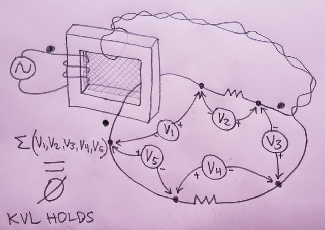
Why not admit that the volt meters would all sum to zero and KVL would at least appear to hold in the above diagram?

Oh that's right, you don't want to go around in circles. Except you are going around in circles about the topic, you just don't want to actually answer a real physics question.
 

Offline Jesse Gordon

  • Regular Contributor
  • *
  • Posts: 126
  • Country: us
Re: #562 – Electroboom!
« Reply #532 on: November 30, 2021, 08:35:27 pm »
Then they posted that textbook page which says that KVL holds if the voltage across the terminals can be unambiguously defined by physical measurements - and by George - we seem to be unambiguously defining the voltages by physical measurements, so I say it's time we all agreed that KVL holds for Lewin's circuit!  :-DD

Except the voltages are not unambiguous:

Not in the circuit above (which is essentially the Lewin ring), not even in the EI core experiment that originally brought you here.
Above, the voltage across "2R" is either "-1/3V" or 2/3V, depending on the path your voltmeter probes are going. That's not what I call "unambiguous".


AHHH THANK YOU! I've been asking for days what was ambiguous about my reading of the voltage on a toroidal transformer secondary!
The answer? If I don't know how many turns are on the winding, especially if they might change without me knowing it, then the reading is ambiguous.
I don't quite know what you're getting at, because I see only single-turn windings, so, would you tell me where you see "transformer secondary" windings in the above diagram?

You've added another secondary winding path. The difference between 2/3v and -1/3v paths is that they wrap around the dB/dt area a different number of times, the difference is one turn.

You're literally asking me to run my volt meter through the transformer, effecting another secondary winding (which you won't allow me to document or model) and you're presenting that as proof of ambiguity.

But the same BS would work on battery packs:

You could just as well say that measuring a 9V battery pack was ambiguous because the volt meter probe could be put inside the battery and connected to some cell tap other than the end terminal.

NO! Just NO!

If we model an element as a black box with two terminals, then you're not allowed to poke your volt meter leads around inside.  That's why we have lumped elements.

The fact that a volt meter probe can be stuck inside a previously lumped element to get a different reading does not mean that reading the voltage on the actual terminals is ambiguous.

Of course moving the probes to another part of the circuit changes the reading.

But that doesn't mean that the reading AT THE TERMINALS is ambiguous.

[EDIT: I updated the diagram below to show designators]

See my diagram below? See how it has terminals AB drawn for the transformer? That's where we're allowed to probe. It's a lumped element. You can't go poking inside it any more than you can measure the voltage across a resistor by probing at some random location along it's physical length.


Do you really think that your ability to move your probes to any of points A,B,C,D,E,F invalidates the reading at AB? Of course AD or DE or AF may be different than AB, but that doesn't make AB ambiguous!

Do you really believe that any measurement is ambiguous because you could probe different locations and get different readings?

Of course measuring between AF like you want will give different reading than between AB. But that doesn't mean AB is ambiguous.

And here's something interesting. You obviously know that the volt meters in the diagram directly above sum to zero.

And yet you can't bring yourself to say "Hey you're right, KVL does appear to hold in that configuration." Why? It obviously appears to hold.

Do you need me to make a video demonstrating it?

Once you come to grips with reality, then you can explain why you think it's not actually holding even though it gives every appearance of holding.

I thought maybe you'd argue based on some definitions or something. But your best argument seems to be saying that reading AB is ambiguous because you could get a different value by reading AF.
« Last Edit: November 30, 2021, 09:02:41 pm by Jesse Gordon »
 

Offline thinkfat

  • Supporter
  • ****
  • Posts: 2150
  • Country: de
  • This is just a hobby I spend too much time on.
    • Matthias' Hackerstübchen
Re: #562 – Electroboom!
« Reply #533 on: November 30, 2021, 09:06:08 pm »
WHERE are you seeing "transformer secondaries"? You're evading answering again.
Everybody likes gadgets. Until they try to make them.
 

Offline HuronKing

  • Regular Contributor
  • *
  • Posts: 230
  • Country: us
Re: #562 – Electroboom!
« Reply #534 on: November 30, 2021, 09:18:50 pm »
And... you don't understand what 'conservative' means when taking about circuits.  It is the energy that is conservative!  In Lewin's circuit, what is the instantaneous power induced in the circuit by means of the external magnetic field?  Now, what is the instantaneous power dissipated by the resistors?  Come on, is not a hard calculation!  If the two are equal, then the fields (plural) are conservative.

Emphasis mine. (Sredni, are you seeing this?!)
Oh my goodness. You think that because energy is conserved that fields must also be conserved? This is just - I don't even know what to say.  :-\

Oh dear oh dear oh dear:
https://courses.lumenlearning.com/physics/chapter/7-5-nonconservative-forces/

It's amazing that you heard me say "the Lewin circuit demonstrates path dependence of non-conservative fields" and INSTANTLY thought this must be about conservation of energy. They're... not the same. You think conserved fields and conserved energy are descriptions of the same thing?  :(

So yea, I guess you should review Newtonian mechanics before we deal with things like circulating magnetic fields:
https://www.pearson.com/content/dam/one-dot-com/one-dot-com/us/en/higher-ed/en/products-services/course-products/wolfson-3e-info/pdf/sample-chapter--ch07.pdf

But I don't even know why I'm linking things for you - you're clearly not opening and reading them.
And I read your post with the circuit - Sredni asked you questions about it that you never answered.


Offline Jesse Gordon

  • Regular Contributor
  • *
  • Posts: 126
  • Country: us
Re: #562 – Electroboom!
« Reply #535 on: November 30, 2021, 09:28:15 pm »

https://i.postimg.cc/jdJntBXT/20211128-121506.jpg

My question is a simple yes or no question. Either the volt meters will sum to zero or they won't. Or maybe you think they might some days depending on the phase of the moon.
If you place your voltmeters all in the same simply connected region that does not include the variable dB/dt region, then yes of course KVL will work. It's written in the top right corner of the picture I have posted more then a week ago. You still have to understand that?

And you still absolutely refuse to answer a simple yes/sometimes/no question regarding the above diagram.

Quote
So far you only proved you can't.

Speak for yourself, it describes you perfectly.

Well, I guess if you can't even answer a simple yes/sometimes/no question, then it's no surprise you can't wrap your mind around Lewin's loop.

Seriously, what's your best guess about the volt meters in the above diagram? Do you think they would sum to zero? or not? or just sometimes?

Maybe it would help you to visualize real world values. How about 100mV per turn induced emf in the transformer core, and  each resistor is 50 ohms.

Dude, lighten up and just answer the question so we can move on. Say "Yes, No, or Sometimes" and there's always the ever popular "I don't know" if that is your case, but if you don't know then you really don't know do you.

If this was chess, you're acting like you're in check. You're acting like you don't want to make a move because you know it'll put you in a bind you can't get out of.

I'm not asking you to try and follow some twisted mental gymnastics and draw a secret diagram I have in my mind.

I drew a simple real-world diagram which you can test yourself with a real transformer and real volt meter and resistors if you want, or if you already know the answer you can just give the answer.

If you can't do that, there's no way the other stuff you're asking is ever going to make sense.

Will the volt meters sum to zero in the above diagram in a real world test? Yes, Sometimes, No.

Thank you!
 

Offline Jesse Gordon

  • Regular Contributor
  • *
  • Posts: 126
  • Country: us
Re: #562 – Electroboom!
« Reply #536 on: November 30, 2021, 09:36:09 pm »
WHERE are you seeing "transformer secondaries"? You're evading answering again.

I edited that post to show the extra secondary in my diagram, also updated the text as well.

You're basically saying I can move my volt meter probes to measure AF instead of AB and get a different reading, therefore AB is ambiguous.


That's a really really weak argument, because you could just as well say that any reading is ambiguous because by moving the probes to another part of the circuit we get a different reading.

But if it's the best you got, polish it to shine as bright as you can.
 

Offline HuronKing

  • Regular Contributor
  • *
  • Posts: 230
  • Country: us
Re: #562 – Electroboom!
« Reply #537 on: November 30, 2021, 09:37:43 pm »
What Mehdi actually says at that point you link above is "Dr. Lewin teaches in one of his courses that KVL doesn't hold true in some cases and I disagree with him."

From the CONTEXT of watching the whole video, it is clear that Mehdi is not claiming that KVL holds in all possible electrical typologies and frequencies, but rather he is specifically talking about certain cases that Lewin and he experimented with.

But yeah, if you want to quote mine, find videos of people who aren't even speaking their native language, I bet you can find slight ambiguities in their out-of-context words which you can present out of context to mean something else.

I've watched his videos... it's kind of right there.

"Dr. Lewin teaches in one of his courses that KVL doesn't hold true in some cases and I disagree with him."

This is a wrong statement. In any context. And he makes the same statement in his conclusion video - despite the warnings Belcher gives him about how to define the integral of the E-field around inductors.

Are there any typologies that Mehdi would accept where KVL is not an appropriate description? I'm not sure that he would. KVL is one of Maxwell's Equations to Mehdi (and I highlighted how profoundly he is confused in my first post in this thread by drawing attention to what he thinks KVL is not and how it contradicts the definition in Feynman that he thinks supports his views - it's madness).

Watch out! Another Lewin cultist spotted!
https://ultimateelectronicsbook.com/electrons-at-rest/
https://ultimateelectronicsbook.com/kirchhoffs-voltage-law-kirchhoffs-current-law/

Quote
However, an electric field with a time-varying magnetic field is not a conservative field. And we use this every day to great practical effect: we intentionally put currents in a loop within time-varying magnetic fields, and use those to extract electrical energy from the time-varying magnetic field (i.e. in generators), or use it to turn electrical energy into magnetic fields (i.e. in motors).

Regardless, we usually encapsulate these electromagnetic effects into our Lumped Element Model, and go on assuming that the electric field actually is conservative.
Understandably, this can be confusing and disorienting to beginners. Ninty-nine percent of the time, it’s safe to just assume the electric field is conservative, but if you’re doing anything with changing or moving magnetic fields, you should make a little mental note to remember that it’s really not.

Damn. Another mind lost to the Lewin infection.


Offline thinkfat

  • Supporter
  • ****
  • Posts: 2150
  • Country: de
  • This is just a hobby I spend too much time on.
    • Matthias' Hackerstübchen
Re: #562 – Electroboom!
« Reply #538 on: November 30, 2021, 09:56:50 pm »
WHERE are you seeing "transformer secondaries"? You're evading answering again.

I edited that post to show the extra secondary in my diagram, also updated the text as well.

You're basically saying I can move my volt meter probes to measure AF instead of AB and get a different reading, therefore AB is ambiguous.


That's a really really weak argument, because you could just as well say that any reading is ambiguous because by moving the probes to another part of the circuit we get a different reading.

But if it's the best you got, polish it to shine as bright as you can.

Nope. Where in MY diagram do you see "transformer secondaries". Point them out, please.
Everybody likes gadgets. Until they try to make them.
 

Offline jesuscf

  • Frequent Contributor
  • **
  • Posts: 499
  • Country: ca
Re: #562 – Electroboom!
« Reply #539 on: November 30, 2021, 10:05:09 pm »
And... you don't understand what 'conservative' means when taking about circuits.  It is the energy that is conservative!  In Lewin's circuit, what is the instantaneous power induced in the circuit by means of the external magnetic field?  Now, what is the instantaneous power dissipated by the resistors?  Come on, is not a hard calculation!  If the two are equal, then the fields (plural) are conservative.

Emphasis mine. (Sredni, are you seeing this?!)
Oh my goodness. You think that because energy is conserved that fields must also be conserved? This is just - I don't even know what to say.  :-\

Oh dear oh dear oh dear:
https://courses.lumenlearning.com/physics/chapter/7-5-nonconservative-forces/

It's amazing that you heard me say "the Lewin circuit demonstrates path dependence of non-conservative fields" and INSTANTLY thought this must be about conservation of energy. They're... not the same. You think conserved fields and conserved energy are descriptions of the same thing?  :(

So yea, I guess you should review Newtonian mechanics before we deal with things like circulating magnetic fields:
https://www.pearson.com/content/dam/one-dot-com/one-dot-com/us/en/higher-ed/en/products-services/course-products/wolfson-3e-info/pdf/sample-chapter--ch07.pdf

But I don't even know why I'm linking things for you - you're clearly not opening and reading them.
And I read your post with the circuit - Sredni asked you questions about it that you never answered.

Wow, you sound a lot like bsfeechannel.  Your ignorance hurts!  Three questions for you: 1) How many fields do we have in the loop circuit with two resistors?  2) What is the instantaneous power induced in the circuit by the external varying magnetic field?  3) What is the instantaneous power consumed by the circuit?  The answers are three real numbers.  Anything else you say is BS.

Don't ask Sredni for help, he is busy trying to calculate the voltage between nodes 'A' and 'D', VAD.
Homer: Kids, there's three ways to do things; the right way, the wrong way and the Max Power way!
Bart: Isn't that the wrong way?
Homer: Yeah, but faster!
 

Offline HuronKing

  • Regular Contributor
  • *
  • Posts: 230
  • Country: us
Re: #562 – Electroboom!
« Reply #540 on: November 30, 2021, 10:22:00 pm »
And... you don't understand what 'conservative' means when taking about circuits.  It is the energy that is conservative!  In Lewin's circuit, what is the instantaneous power induced in the circuit by means of the external magnetic field?  Now, what is the instantaneous power dissipated by the resistors?  Come on, is not a hard calculation!  If the two are equal, then the fields (plural) are conservative.

Emphasis mine. (Sredni, are you seeing this?!)
Oh my goodness. You think that because energy is conserved that fields must also be conserved? This is just - I don't even know what to say.  :-\

Oh dear oh dear oh dear:
https://courses.lumenlearning.com/physics/chapter/7-5-nonconservative-forces/

It's amazing that you heard me say "the Lewin circuit demonstrates path dependence of non-conservative fields" and INSTANTLY thought this must be about conservation of energy. They're... not the same. You think conserved fields and conserved energy are descriptions of the same thing?  :(

So yea, I guess you should review Newtonian mechanics before we deal with things like circulating magnetic fields:
https://www.pearson.com/content/dam/one-dot-com/one-dot-com/us/en/higher-ed/en/products-services/course-products/wolfson-3e-info/pdf/sample-chapter--ch07.pdf

But I don't even know why I'm linking things for you - you're clearly not opening and reading them.
And I read your post with the circuit - Sredni asked you questions about it that you never answered.

Wow, you sound a lot like bsfeechannel.  Your ignorance hurts!  Three questions for you: 1) How many fields do we have in the loop circuit with two resistors?  2) What is the instantaneous power induced in the circuit by the external varying magnetic field?  3) What is the instantaneous power consumed by the circuit?  The answers are three real numbers.  Anything else you say is BS.

Don't ask Sredni for help, he is busy trying to calculate the voltage between nodes 'A' and 'D', VAD.

Ah you refuse to learn about energy conservation as opposed to field conservation. No wonder Faraday's Law seems like a big inscrutable mystery that only KVL can save you from.

Did you open any of those links? Have you opened anything I've linked? Have you read Kraus, chapter 4? Or chapter 10? It's easy to find online.

Let me guess, you're going to say...
"That's all BS!"

« Last Edit: November 30, 2021, 10:35:29 pm by HuronKing »
 

Offline jesuscf

  • Frequent Contributor
  • **
  • Posts: 499
  • Country: ca
Re: #562 – Electroboom!
« Reply #541 on: November 30, 2021, 10:42:25 pm »
And... you don't understand what 'conservative' means when taking about circuits.  It is the energy that is conservative!  In Lewin's circuit, what is the instantaneous power induced in the circuit by means of the external magnetic field?  Now, what is the instantaneous power dissipated by the resistors?  Come on, is not a hard calculation!  If the two are equal, then the fields (plural) are conservative.

Emphasis mine. (Sredni, are you seeing this?!)
Oh my goodness. You think that because energy is conserved that fields must also be conserved? This is just - I don't even know what to say.  :-\

Oh dear oh dear oh dear:
https://courses.lumenlearning.com/physics/chapter/7-5-nonconservative-forces/

It's amazing that you heard me say "the Lewin circuit demonstrates path dependence of non-conservative fields" and INSTANTLY thought this must be about conservation of energy. They're... not the same. You think conserved fields and conserved energy are descriptions of the same thing?  :(

So yea, I guess you should review Newtonian mechanics before we deal with things like circulating magnetic fields:
https://www.pearson.com/content/dam/one-dot-com/one-dot-com/us/en/higher-ed/en/products-services/course-products/wolfson-3e-info/pdf/sample-chapter--ch07.pdf

But I don't even know why I'm linking things for you - you're clearly not opening and reading them.
And I read your post with the circuit - Sredni asked you questions about it that you never answered.

Wow, you sound a lot like bsfeechannel.  Your ignorance hurts!  Three questions for you: 1) How many fields do we have in the loop circuit with two resistors?  2) What is the instantaneous power induced in the circuit by the external varying magnetic field?  3) What is the instantaneous power consumed by the circuit?  The answers are three real numbers.  Anything else you say is BS.

Don't ask Sredni for help, he is busy trying to calculate the voltage between nodes 'A' and 'D', VAD.

Ah you refuse to learn about energy conservation as opposed to field conservation. No wonder Faraday's Law seems like a big inscrutable mystery that only KVL can save you from.

Did you open any of those links? Have you opened anything I've linked? Have you read Kraus, chapter 4? Or chapter 10? It's easy to find online.

Let me guess, you're going to say...
"That's all BS!"

I understand your diversionary tactics and I will not fall for them.  Let us concentrate in the solution of Lewin's original problem.  Now, the three numerical answers are:

1) ____ fields.

2) ____ W.

3) ____ W.

Fill in the blanks.


Homer: Kids, there's three ways to do things; the right way, the wrong way and the Max Power way!
Bart: Isn't that the wrong way?
Homer: Yeah, but faster!
 

Offline Jesse Gordon

  • Regular Contributor
  • *
  • Posts: 126
  • Country: us
Re: #562 – Electroboom!
« Reply #542 on: November 30, 2021, 10:46:01 pm »
WHERE are you seeing "transformer secondaries"? You're evading answering again.

I edited that post to show the extra secondary in my diagram, also updated the text as well.

You're basically saying I can move my volt meter probes to measure AF instead of AB and get a different reading, therefore AB is ambiguous.


That's a really really weak argument, because you could just as well say that any reading is ambiguous because by moving the probes to another part of the circuit we get a different reading.

But if it's the best you got, polish it to shine as bright as you can.

Nope. Where in MY diagram do you see "transformer secondaries". Point them out, please.

My diagram literally shows the same topology as yours including the additional secondary.

But if you want me to actually show it in your diagram, fine, I'll do it after you answer the following YES or NO question. I asked you before and you refuse to answer me.

Question: In the following diagram, in a real life physical lab test performed with real (time synchronized) volt meters with a real transformer and real resistors CONNECTED AS SHOWN, will the readings of all the volt meters sum to zero, within the accuracy and resolution limitations of the volt meters? YES or NO.
(Or if you believe SOMETIMES is the answer, then explain one scenario for a YES condition and one scenario for a NO condition WITH THE VOLT METERS CONNECTED AS SHOWN - Running additional conductors through the transformer core is not allowed - nor is removing existing conductors from through the transformer core!)


Seriously, other than intentional repositioning of probes or intentional changes of details inside my lumped elements, all the measurements above are unambiguous.
 

Offline Sredni

  • Frequent Contributor
  • **
  • Posts: 686
  • Country: aq
Re: #562 – Electroboom!
« Reply #543 on: November 30, 2021, 10:46:28 pm »

https://i.postimg.cc/jdJntBXT/20211128-121506.jpg

My question is a simple yes or no question. Either the volt meters will sum to zero or they won't. Or maybe you think they might some days depending on the phase of the moon.
If you place your voltmeters all in the same simply connected region that does not include the variable dB/dt region, then yes of course KVL will work. It's written in the top right corner of the picture I have posted more then a week ago. You still have to understand that?

And you still absolutely refuse to answer a simple yes/sometimes/no question regarding the above diagram.
--snip--
Seriously, what's your best guess about the volt meters in the above diagram? Do you think they would sum to zero? or not? or just sometimes?

Maybe it would help you to visualize real world values. How about 100mV per turn induced emf in the transformer core, and  each resistor is 50 ohms.

Dude, lighten up and just answer the question so we can move on. Say "Yes, No, or Sometimes" and there's always the ever popular "I don't know" if that is your case, but if you don't know then you really don't know do you.

If this was chess, you're acting like you're in check. You're acting like you don't want to make a move because you know it'll put you in a bind you can't get out of.

I'm not asking you to try and follow some twisted mental gymnastics and draw a secret diagram I have in my mind.

I drew a simple real-world diagram which you can test yourself with a real transformer and real volt meter and resistors if you want, or if you already know the answer you can just give the answer.

If you can't do that, there's no way the other stuff you're asking is ever going to make sense.

Will the volt meters sum to zero in the above diagram in a real world test? Yes, Sometimes, No.

Thank you!

This reminds me of when I was a kid. My cousin has this motorcycle - more of a scooter - that had to be started by jumping on a sort of lever. It never started at the first jolt. It usually needed three or four jumps.
I wonder if it's the same with you.
Here. Reread my answer. I'll add a few cues.

Here's the picture I was talking about:


It's literally titled: "KVL-works-if-I-leave-out-the-magnetic-region.jpg"
Does the ".jpg" confuse you? Or is it the dashes?
If you look at the top right corner, it says: "KVL works here".
What part of "KVL works here" you do not understand? "KVL"? "works"? "here"?

I hope it is clear that if you choose to look at a lumpABLE circuit as a lumpED circuit, then KVL works.

Wrooom... wrooom.... ?

?

Maybe that tank of yours is empty?
All instruments lie. Usually on the bench.
 

Offline HuronKing

  • Regular Contributor
  • *
  • Posts: 230
  • Country: us
Re: #562 – Electroboom!
« Reply #544 on: November 30, 2021, 10:49:22 pm »
And... you don't understand what 'conservative' means when taking about circuits.  It is the energy that is conservative!  In Lewin's circuit, what is the instantaneous power induced in the circuit by means of the external magnetic field?  Now, what is the instantaneous power dissipated by the resistors?  Come on, is not a hard calculation!  If the two are equal, then the fields (plural) are conservative.

Emphasis mine. (Sredni, are you seeing this?!)
Oh my goodness. You think that because energy is conserved that fields must also be conserved? This is just - I don't even know what to say.  :-\

Oh dear oh dear oh dear:
https://courses.lumenlearning.com/physics/chapter/7-5-nonconservative-forces/

It's amazing that you heard me say "the Lewin circuit demonstrates path dependence of non-conservative fields" and INSTANTLY thought this must be about conservation of energy. They're... not the same. You think conserved fields and conserved energy are descriptions of the same thing?  :(

So yea, I guess you should review Newtonian mechanics before we deal with things like circulating magnetic fields:
https://www.pearson.com/content/dam/one-dot-com/one-dot-com/us/en/higher-ed/en/products-services/course-products/wolfson-3e-info/pdf/sample-chapter--ch07.pdf

But I don't even know why I'm linking things for you - you're clearly not opening and reading them.
And I read your post with the circuit - Sredni asked you questions about it that you never answered.

Wow, you sound a lot like bsfeechannel.  Your ignorance hurts!  Three questions for you: 1) How many fields do we have in the loop circuit with two resistors?  2) What is the instantaneous power induced in the circuit by the external varying magnetic field?  3) What is the instantaneous power consumed by the circuit?  The answers are three real numbers.  Anything else you say is BS.

Don't ask Sredni for help, he is busy trying to calculate the voltage between nodes 'A' and 'D', VAD.

Ah you refuse to learn about energy conservation as opposed to field conservation. No wonder Faraday's Law seems like a big inscrutable mystery that only KVL can save you from.

Did you open any of those links? Have you opened anything I've linked? Have you read Kraus, chapter 4? Or chapter 10? It's easy to find online.

Let me guess, you're going to say...
"That's all BS!"

I understand your diversionary tactics and I will not fall for them.  Let us concentrate in the solution of Lewin's original problem.  Now, the three numerical answers are:

1) ____ fields.

2) ____ W.

3) ____ W.

Fill in the blanks.

So the answer is no, no, and no.

Ah you're right. Faraday's Law fields are always conservative. You win.

...

Nah, even a lie that big is too much for me to utter without laughing in your face. Lolz - referencing textbooks that discuss the phenomena you don't get in all its wonderful mathematical detail is diversionary.  :-DD :-DD
« Last Edit: November 30, 2021, 10:51:49 pm by HuronKing »
 

Offline jesuscf

  • Frequent Contributor
  • **
  • Posts: 499
  • Country: ca
Re: #562 – Electroboom!
« Reply #545 on: November 30, 2021, 10:54:29 pm »
And... you don't understand what 'conservative' means when taking about circuits.  It is the energy that is conservative!  In Lewin's circuit, what is the instantaneous power induced in the circuit by means of the external magnetic field?  Now, what is the instantaneous power dissipated by the resistors?  Come on, is not a hard calculation!  If the two are equal, then the fields (plural) are conservative.

Emphasis mine. (Sredni, are you seeing this?!)
Oh my goodness. You think that because energy is conserved that fields must also be conserved? This is just - I don't even know what to say.  :-\

Oh dear oh dear oh dear:
https://courses.lumenlearning.com/physics/chapter/7-5-nonconservative-forces/

It's amazing that you heard me say "the Lewin circuit demonstrates path dependence of non-conservative fields" and INSTANTLY thought this must be about conservation of energy. They're... not the same. You think conserved fields and conserved energy are descriptions of the same thing?  :(

So yea, I guess you should review Newtonian mechanics before we deal with things like circulating magnetic fields:
https://www.pearson.com/content/dam/one-dot-com/one-dot-com/us/en/higher-ed/en/products-services/course-products/wolfson-3e-info/pdf/sample-chapter--ch07.pdf

But I don't even know why I'm linking things for you - you're clearly not opening and reading them.
And I read your post with the circuit - Sredni asked you questions about it that you never answered.

Wow, you sound a lot like bsfeechannel.  Your ignorance hurts!  Three questions for you: 1) How many fields do we have in the loop circuit with two resistors?  2) What is the instantaneous power induced in the circuit by the external varying magnetic field?  3) What is the instantaneous power consumed by the circuit?  The answers are three real numbers.  Anything else you say is BS.

Don't ask Sredni for help, he is busy trying to calculate the voltage between nodes 'A' and 'D', VAD.

Ah you refuse to learn about energy conservation as opposed to field conservation. No wonder Faraday's Law seems like a big inscrutable mystery that only KVL can save you from.

Did you open any of those links? Have you opened anything I've linked? Have you read Kraus, chapter 4? Or chapter 10? It's easy to find online.

Let me guess, you're going to say...
"That's all BS!"

I understand your diversionary tactics and I will not fall for them.  Let us concentrate in the solution of Lewin's original problem.  Now, the three numerical answers are:

1) ____ fields.

2) ____ W.

3) ____ W.

Fill in the blanks.

So the answer is no, no, and no.

Ah you're right. Faraday's Law fields are always conservative. You win.

...

Nah, even a lie that big is too much for me to utter without laughing in your face.  :-DD :-DD

I'll leave the questions unanswered for now.  Let see if any one else from team Lewin comes forward to help you.
Homer: Kids, there's three ways to do things; the right way, the wrong way and the Max Power way!
Bart: Isn't that the wrong way?
Homer: Yeah, but faster!
 

Offline jesuscf

  • Frequent Contributor
  • **
  • Posts: 499
  • Country: ca
Re: #562 – Electroboom!
« Reply #546 on: November 30, 2021, 10:57:32 pm »

https://i.postimg.cc/jdJntBXT/20211128-121506.jpg

My question is a simple yes or no question. Either the volt meters will sum to zero or they won't. Or maybe you think they might some days depending on the phase of the moon.
If you place your voltmeters all in the same simply connected region that does not include the variable dB/dt region, then yes of course KVL will work. It's written in the top right corner of the picture I have posted more then a week ago. You still have to understand that?

And you still absolutely refuse to answer a simple yes/sometimes/no question regarding the above diagram.
--snip--
Seriously, what's your best guess about the volt meters in the above diagram? Do you think they would sum to zero? or not? or just sometimes?

Maybe it would help you to visualize real world values. How about 100mV per turn induced emf in the transformer core, and  each resistor is 50 ohms.

Dude, lighten up and just answer the question so we can move on. Say "Yes, No, or Sometimes" and there's always the ever popular "I don't know" if that is your case, but if you don't know then you really don't know do you.

If this was chess, you're acting like you're in check. You're acting like you don't want to make a move because you know it'll put you in a bind you can't get out of.

I'm not asking you to try and follow some twisted mental gymnastics and draw a secret diagram I have in my mind.

I drew a simple real-world diagram which you can test yourself with a real transformer and real volt meter and resistors if you want, or if you already know the answer you can just give the answer.

If you can't do that, there's no way the other stuff you're asking is ever going to make sense.

Will the volt meters sum to zero in the above diagram in a real world test? Yes, Sometimes, No.

Thank you!

This reminds me of when I was a kid. My cousin has this motorcycle - more of a scooter - that had to be started by jumping on a sort of lever. It never started at the first jolt. It usually needed three or four jumps.
I wonder if it's the same with you.
Here. Reread my answer. I'll add a few cues.

Here's the picture I was talking about:


It's literally titled: "KVL-works-if-I-leave-out-the-magnetic-region.jpg"
Does the ".jpg" confuse you? Or is it the dashes?
If you look at the top right corner, it says: "KVL works here".
What part of "KVL works here" you do not understand? "KVL"? "works"? "here"?

I hope it is clear that if you choose to look at a lumpABLE circuit as a lumpED circuit, then KVL works.

Wrooom... wrooom.... ?

?

Maybe that tank of yours is empty?

You are back!  Have you figured out how to CALCULATE the voltage between nodes 'A' and 'D' yet?  Show us!
Homer: Kids, there's three ways to do things; the right way, the wrong way and the Max Power way!
Bart: Isn't that the wrong way?
Homer: Yeah, but faster!
 

Offline Sredni

  • Frequent Contributor
  • **
  • Posts: 686
  • Country: aq
Re: #562 – Electroboom!
« Reply #547 on: November 30, 2021, 11:02:08 pm »
You are back!  Have you figured out how to CALCULATE the voltage between nodes 'A' and 'D' yet?  Show us!

Your tank is sure dry.
Because I have already told you at least four times that it depends on the path, and I have calculated it for two paths already.
All instruments lie. Usually on the bench.
 

Offline jesuscf

  • Frequent Contributor
  • **
  • Posts: 499
  • Country: ca
Re: #562 – Electroboom!
« Reply #548 on: November 30, 2021, 11:09:35 pm »
You are back!  Have you figured out how to CALCULATE the voltage between nodes 'A' and 'D' yet?  Show us!

Your tank is sure dry.
Because I have already told you at least four times that it depends on the path, and I have calculated it for two paths already.

Nope.  The answers you provided are the voltages MEASURED by the 'voltmeters' on the left and right.  CALCULATE the voltage VAD; you can use either the left branch or the right branch.
Homer: Kids, there's three ways to do things; the right way, the wrong way and the Max Power way!
Bart: Isn't that the wrong way?
Homer: Yeah, but faster!
 

Offline thinkfat

  • Supporter
  • ****
  • Posts: 2150
  • Country: de
  • This is just a hobby I spend too much time on.
    • Matthias' Hackerstübchen
Re: #562 – Electroboom!
« Reply #549 on: November 30, 2021, 11:09:37 pm »
WHERE are you seeing "transformer secondaries"? You're evading answering again.

I edited that post to show the extra secondary in my diagram, also updated the text as well.

You're basically saying I can move my volt meter probes to measure AF instead of AB and get a different reading, therefore AB is ambiguous.


That's a really really weak argument, because you could just as well say that any reading is ambiguous because by moving the probes to another part of the circuit we get a different reading.

But if it's the best you got, polish it to shine as bright as you can.

Nope. Where in MY diagram do you see "transformer secondaries". Point them out, please.

My diagram literally shows the same topology as yours including the additional secondary.

But if you want me to actually show it in your diagram, fine, I'll do it after you answer the following YES or NO question. I asked you before and you refuse to answer me.

Question: In the following diagram, in a real life physical lab test performed with real (time synchronized) volt meters with a real transformer and real resistors CONNECTED AS SHOWN, will the readings of all the volt meters sum to zero, within the accuracy and resolution limitations of the volt meters? YES or NO.
(Or if you believe SOMETIMES is the answer, then explain one scenario for a YES condition and one scenario for a NO condition WITH THE VOLT METERS CONNECTED AS SHOWN - Running additional conductors through the transformer core is not allowed - nor is removing existing conductors from through the transformer core!)


Seriously, other than intentional repositioning of probes or intentional changes of details inside my lumped elements, all the measurements above are unambiguous.

Nope. No more bobbing and weaving for you. No more smoke bombs. You don't answer simply because the answer would reveal the inconsistencies in your "modeling of reality". So which of the loops in MY diagram are "transformer secondaries"?
Everybody likes gadgets. Until they try to make them.


Share me

Digg  Facebook  SlashDot  Delicious  Technorati  Twitter  Google  Yahoo
Smf